John Carroll
-
Posts
577 -
Joined
-
Last visited
-
Days Won
3
Everything posted by John Carroll
-
So, the return temp to the boiler must be 41C, the (boiler) flow temp is 60C, dT, 60-41, 19C, UFH dT, 48-41, 7C, boiler flowrate, 10*7/19, 3.68LPM, so there obviously is HW being recirculated to give that higher return temp, the only downside of this is that the boiler efficiency will be lower at the higher return temp so maybe just look at this, rather than trying to get longer cycle times etc by creating a bigger heat demand or whatever, your system is, IMO, performing very well, why not leave it be. The "picture" below might be easier to understand UFH mixing etc and you can do your own calcs. UFH Calculations with Bypass Extract Rev0.xlsx
-
Cant see the bottom (return) gauge properly but if its the same as the top one (scale wise) then maybe reading 40/42C ish? so ~ 7C dT, fairly normal, so UFH output 2.5*4*60*(48-41)/860, 4.88kw?, or there abouts.
-
The cut in temp on the majority of (gas fired) boilers is when the anticycle time has elapsed once the flow temp is target temp - 5C, I have seen posts re some boilers which have a settable (negative) hysteresis where the cut in is either at this target-hysteresis OR the anticycle time.
-
The (any) boiler should not refire until the flow temp is target temp - 5C, 60-5, 55C in this case, any modulating boiler cannot work if either the cut in/cut out are at target temp.
-
Can you go to the UFH manifold and read off the flowrates from each loop as accurately as possible from the flow meters ("glass tubes") and also the manifold flow & return temperatures when the boiler has been firing for say 5/7 minutes, also note the boiler flow & return temperatures. Your boiler may have a internal bypass which would account for the difference in displayed return temp & the measured return temp, you could alos shut that bypass after say 5 minutes, note the boiler flow&return temps before shutting it and after another say 1 minute recheck those temperatures, I would then recommend returning the by pass to its original setting. You are doing very well with that cycle time IMO, your cycle time suggests a UFH/boiler demand of at least, 6*9/12, 4.5kw but will probably be more as the boiler will fire at 20kw (its max on CH) for a few minutes to get the flow temp up to its target temp of 60C and then ramp down to its minimum of 6kw, your manifold data will give a fair idea of what the demand actually is (roughly). Edit: whats this €2.50 cost? is it per day or what.
-
Maybe not quite what you are looking for. https://blog.heatspring.com/2-pipe-versus-4-pipe-buffer-tank-configurations/
-
Seems to be a lot of bypassing , if the UFH return temp is say 38C then ~ 3.5LPM at ~ 38C must be mixing with ~ 5.0LPM at 60C of bypass (assuming no temp drop through the rad), to give a buffer temperature of 51C, the manifold return should be well down to its return temperature after 30 minutes, your UFH system with 400M of 16MM (12mm ID) piping should contain around a total of 95L, (45L in the pipework + the 50L buffer) will/should have circulated through the system after ~ 95/3.5, 27 minutes, check those readings again sometime after say 3 cycles. Its no wonder the boiler was short cycling with (If) that sort of bypassing.
-
(say) 30 minutes on & 3 minutes Off is a cycle time of 33 minutes, not even 2 cycles/hour, nothing to complain about now?, and assuming 6kw min output means a UFH demand of 6*30/33, 5.45kw?.
-
So, what is the cycle time?, now, at 60C target temp, ie, burner ON time & burner Off time. Can you post a link to your Boiler MIs. A 3 minute anticycle time is very short, but probably set in stone on your boiler, here is the look up table for a Vaillant, (think Glowworm is similar, owned by Vaillant??) which is based on a anticycle time of 20 minutes at a target temp of 20C!!, the higher the target temp then the shorter the anticycle time. A default setting of 20C set anticycle time with a target temp of 60C gives a actual anticycle time of 6 minutes. The problem with UFH is that if a high target temp is required to get the boiler away then the the return flow is lower, for example, a UFH demand of say 5kw with flow return temps of 45C/37C will have a flow rate of 5*860/60/(45-37), 8.96 lpm but the flow return to the boiler (assuming 60C flow temp) will only be, 8.96*(45-37)/(60-37), 3.12LPM. (With 5.84LPM at 37C mixing with that 3.12LPM at 60C to give a UFH manifold temp of 45C). Vaillant anticycle times general.docx
-
What make/ output Boiler do you have?, its quite a achievment IMO to get any gas boiler to fire up and stay lighting in one go with such a low target temperature, some boilers, like Vaillant maintain (or used to) ignition conditions for 60 secs for some reason or other making it even more difficult to get the boiler away and required a very long anti cycle time or/and a high target temperature.
-
All gas boilers fire up at ~ 65% of max output before modulating down, if you have a 30kw boiler then it will fire up at 30*65%, 19.5kw, if its set to say a target temp of 45C, then the burner will trip at target temp+5C, 50C, its very unlikely that the flow temperature on fire up will be less than 30C so the flowrate must be sufficiently high enough to maintain a dT of 50-30, 20C, (until it modulates down to its min output or whatever) which requires a flowrate of 19.5*860/60/20, 13.98LPM, if the flowrate isn't at least at this level then it doesn't matter what capacity buffer/volumiser you have installed, if you set the target temp to a more "normal" say 65C, then the flowrate only has to be 19.5*860/60/(70-30), 6.98LPM to exceed a burner trip temperature of 70C, ideally the flow temperature should just about reach target temperature so a flowrate of 8.0LPM required. At a target temp of 60C, these two flowrates are 8.0 and 9.3LPM, at a target temp of 50C are 11.18 and 14.0LPM, etc. Also if the UFH manifold TMV is sluggish in operation, it might be returning a flowrate (to the boiler) well less than the above. Suggest, initially setting the target temp as high as is required to get the boiler away without cycling, then you can gradually reduce it to its optimum setting, obviously the boiler will still cycle when/if the UFH demand is less than the boiler's minimum output but this is quite normal and unavoidable.
-
Would this work?, I'm assuming the boiler fires flat out in one case(s) and at its minimum output of 6kw? in the other case(s), depends on how fast the boiler ramps down once the target temp is reached after firing up. When/if the heating demand exceeds the minimum boiler output, then the boiler should fire continuously. External Flowside Buffer Extract Rev0.xlsx
-
Vaillant EcoTec Plus 630 dT
John Carroll replied to John Carroll's topic in Boilers & Hot Water Tanks
Thanks for that, You can see from the above that the flowrates and boiler outputs both on dP control at 100mbar (should = ~ 43% pump speed) and 50% fixed speed control are roughly the same, or at least quite good enough to show that the dP conrol mode is working quite reasonably well. The problem boiler works perfectly well in fixed speed mode but not on dP control, see example data, below, the pump runs at 83% and higher at a dP request of 100mbar, the pump speed should be down around 43/50% with a flowrate of 950LPH, the flowrates will be far higher than yours at any given pump speed because of the LLH where the only pressure loss is through the boiler HEX plus a very very small loss through the pipework to the adjacent LLH. D.171 = 100mbar, (dP control) Target modulation = 63% = 0.63*30, 18.9kw D.015 = 83% D.029 = 1,576 l/h = 1576*(62-50)/860,21.99kw D.040 = 62C D.041 = 50C -
TRVs not responding to room temperature
John Carroll replied to Little Clanger's topic in Central Heating (Radiators)
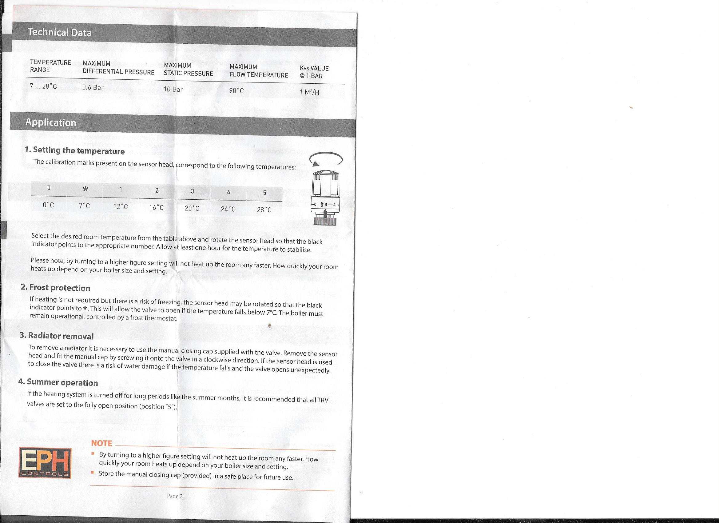
If I use my thumb with something covering it, then, yes, can push it, but not easily, maybe thats why my pins never stick in the one position!. At index 2 my actuator will certainly be pushing the pin in a fair bit and will be fully shut off at a room temp of 18/20C, all these (proportional) actuators work the same, at a fairly low setting like index 2, the valve will only be a mm or so from fully shut so a relatively small temperature rise will throttle it still further and even close it, I would think that the actuator should just about be touching the pin even on setting 5 with the valve just fully open I will be purchasing/replacing one in the next few days so will take a few readings before installing it.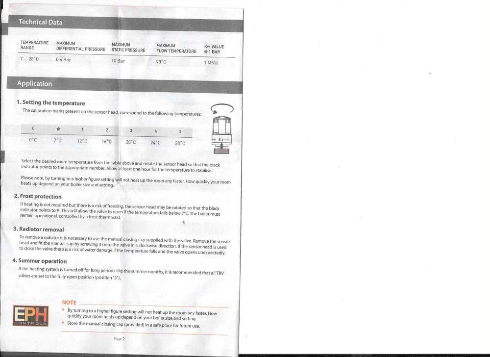
-
TRVs not responding to room temperature
John Carroll replied to Little Clanger's topic in Central Heating (Radiators)
NO way should finger pressure push the pin in except you're Superman with a steel finger, I use the handle of a reversed hammer to push the pin in, it should then spring back out ~ 3/5mm. Any failures I've had is that the spring fails, so they won't open once the temperature drops, I've never had a actuator failure apart from some ancient ones where the plastic has become brittle and they have fallen off. I've just noticed a pin (valve) failure on one of my EPH TRVs, a bit disappointed as these normally last ~ 8 years, this one is only 4/5 years old. I often see reference (like above) to the pin sticking say after a summer of no use but I've never experienced this, most of my TRV (8) settings are never touched throughout their lifetimes. -
TRVs not responding to room temperature
John Carroll replied to Little Clanger's topic in Central Heating (Radiators)
Ensure the actuator is turned fully anticlockwise (fully open) before attaching it to the valve. -
Thoughts on Different Brands of Unvented Cylinders
John Carroll replied to steveoelliott's topic in General Plumbing
This is just one but there are others floating around. https://www.diynot.com/diy/threads/noise-from-unvented-hot-water-system.590373/ -
Thoughts on Different Brands of Unvented Cylinders
John Carroll replied to steveoelliott's topic in General Plumbing
Didn't Baxi? say they would replace the Megaflo FOC?. -
Thoughts on Different Brands of Unvented Cylinders
John Carroll replied to steveoelliott's topic in General Plumbing
I've seen a good few posts (re Gledhill LITE)) on various sites re noisy operation, in some, the cylinder was replaced, one batch were noisy apparently because the insulation hadn't been given enough time to cure properly on manufacture. -
Vaillant EcoTec Plus 630 dT
John Carroll replied to John Carroll's topic in Boilers & Hot Water Tanks
It seems the both these pumps don't perform as per spec on either constant dP or Spread dT modes. @burgessl pump above was showing flow rates of 700 to 1200LPH at a the default setting of 200mbar (2.0M) on the default hydraulic mode of dP constant. I have very accurate flow readings for a 6M (Wilo) circ pump running at both 6M and 2.0M above, and its quite easy to see that there is no residual head remaing after passing through the boiler HEX to push water through the rads at a flow rate of 1075LPH, pump head is 1.85M and the HEX pressure loss is 1.85M, if the pump was running at its full speed and head of 6M then the pump head at 1075LPH is 5.05M so residual head is 5.05-1.85, 3.2M, quite capable of circulating 1075LPH through rads etc IMO. Likewise the dT test above shows a pump speed of 35% and a corrected flow rate of 645LPH (from indicated 836), the pump head at 35% speed is only 0.74M, the HEX pressure loss at 645LPH is 1.04M, it might circulate ~ 200LPH through the rads if the system resistance is low enough. Residual Pump Head. burgessi.xlsx -
Thoughts on Different Brands of Unvented Cylinders
John Carroll replied to steveoelliott's topic in General Plumbing
If Space not a problem, install one (UVC) with a external EV, if it is a problem install a OSO which does have a internal bubble but no daft baffle, you can always remove the dip tube and install a EV later. -
If the vent height was like it is now I'd say you would never have had a problem because of that big bore 28mm? H.
-
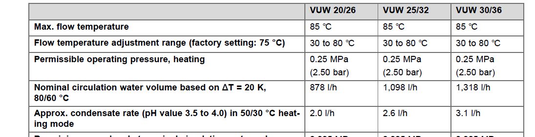
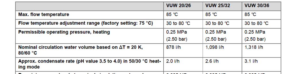
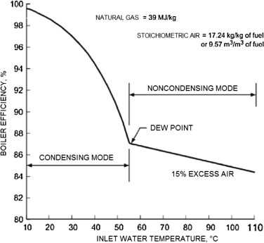
From my many many years on Steam Driven Plants, or look up Spirax Sarco Steam Tables, or even Google, you will see that it requires 2257kj to evaporate 1kg of water, its good enough to call 1kg of water 1L, so 2257kj/L = 2257/3600, 0.62694kwh/L, = 1/0.62694, 1.595L/kwh, the wet gas loss of nat gas is ~ 10% = 1.595*10%, 0.1595L/kwh of fuel burned, in other words if a boiler is fully condensing then the condensate flow should be 0.1595L for every kwh of fuel burned, a 28.5kw boiler will burn 30kwh/hr of gas at 95% efficiency which should result in a condensate flow of 30*0.1595, 4.785LPH, I have seen numbers of 3.5L/30kwh if fully condensing, this is only 73% of my calculated figures so maybe some mistake in my calcs, Vaillant MIs state condensing flow of 3.1L for a 30kw (output) 630 at flow/return temps of 50/30 which is close to fully condensing so there must be something up with my calcs but not sure where. ( The boiler numbers would be true (compared to mine) if burning oil which has a wet gas loss of ~ 6.5%. Anyway get out your bucket and run the condensate into it for say 30 minutes, taking the gas meter readings at the start and finish.
-
This is the sort of efficiency chart that IMO is (more) correct as its based on the HHV of the fuel which, after all, we are charged on. If I had a gas boiler I would measure the condensate flow, that will then give a very accurate number for the boiler efficiency.
-
Vaillant EcoTec Plus 630 dT
John Carroll replied to John Carroll's topic in Boilers & Hot Water Tanks
The problem (30kw) when set to dP (constant pressure) below set to 100mbar (1.0M) still maintained 83% pump speed, which, assuming a Vaillant advised installed 5.5M pump means that the pump head at 83% is 5.5*0.83^2, 3.79M or 379mbar despite a requested head of 100mbar. The pump flow when changed to fixed speed and set to its lowest speed of 50% was a corrected 692LPH, the pressure loss through the boiler HEX is 2.6M at its rated flow of 1290LPH so at a flowrate of 692LPH is 2.6*(692/1290)^2, 0.748M, 50% pump speed is a pump head of 5.5*0.5^2, 1.38M, 138mbar which approximates to the 0.7M at 692LPM through the boiler HEX, so no reason whatsoever IMO as to why the pump speed wasn't driven down to ~ 50% on dP control, the same should apply on Spread dT control, it just will not drive the pump speed down to at least 50% which we know is ~ 138mbar, well above the 100mbar minimum allowed. This is why I'm interested in the results from another boiler, without a LLH, set to dP control at 100mbar to see how low the pump speed falls to. D.170 option 2 (Bypass, dP constant): D171 dP 100mbar Target modulation = 63% = 18.9kw D.015 = 83% D.029 = 1,576 l/h D.040 = 62C D.041 = 50C = 21.99kw ( X 1.164)