John Carroll
-
Posts
577 -
Joined
-
Last visited
-
Days Won
3
Everything posted by John Carroll
-
Vaillant EcoTec Plus 630 dT
John Carroll replied to John Carroll's topic in Boilers & Hot Water Tanks
I see you have a 625 but I think the the tests are still valid ie test 1 mod output is 0.12*25, 3.0kw, test 3 mod output is 0.39*25, 9.75kw, calculated output, 3.203*3.0, 9.6kw. -
Vaillant EcoTec Plus 630 dT
John Carroll replied to John Carroll's topic in Boilers & Hot Water Tanks
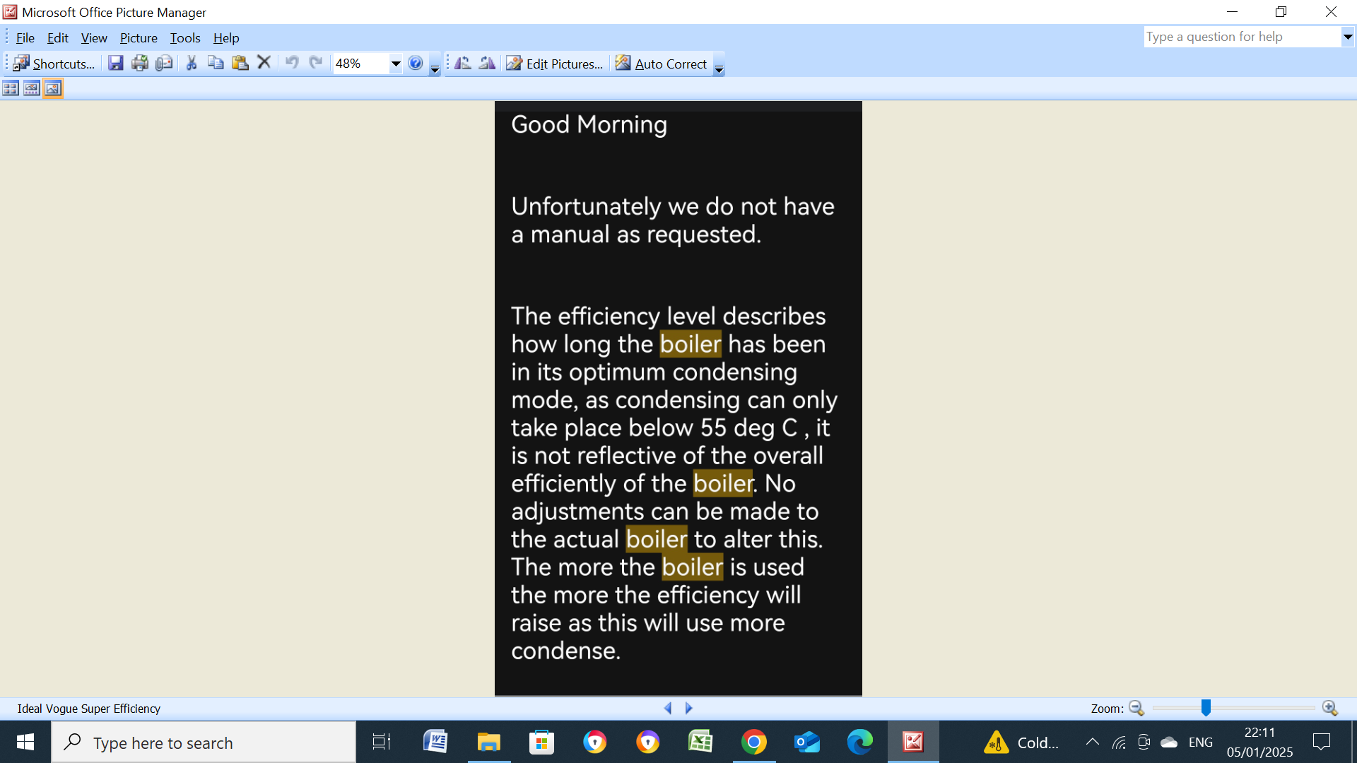
Fantastic info. just whats needed. Won't go through the dreary calcs but test 1 shows 3.6kw & 4.38kw Mod.calc vs flow/dT calc). flow/dt calc +20% test 2 16.2kw vs 18.07kw. flow/dT calc + 11.5% test 3 11.7kw vs 12.6kw. flow/dT calc +8% as with the "problem" boiler the dt/flow calc is consistently higher than the modulation output calc but this flowrate is probably derived from the smart pump power and calculated efficiency but at least is reasonably accurate enough to see it changing with pump speeds. The second test shows that the dT of 19C is almost at the requested dT but this might just possible because the system was still settling down with that huge change. The third test is the most interesting because its output is almost directly proportional to your steady state test 1 where the output was 3.6kw, at this test the flow/return temps were 37C/32C, assuming a room temp of 20C then you had (37+32)/2 - 20, a T14.5C "rad" the third test with flow/return temps of 62C/49C, gives a (62+49)/2 - 20, a T35.5 "rad" which will result in a factor of (35.5/14.5)^1.3, 3.203, to give a output of 3.203*3.6, 11.53kw which is almost spot on with the mod. output of (0.39*30),11.7kw. The reason for this rigmarole is just to be satisfied that the system had settled down, BUT the target dT of 20C was not achieved, it was "only" 13C, one could say why not, maybe the answer lies (even though I'm doubtful) in that the spread dT is limited if the pump dP falls to 100mbar (1.0M) as shown by D.173 (minimum pressure level while in spread dT). Now, the circ pump head is 5.5M as advised by Vaillant tech to me, I am skeptical of this and would venture its more likely to be nearer a 7M pump, IF its a 5.5M pump then because dP is proportional to speed squared, the dP in test 3 was only 5.5*0.35^2, 0.673M (67.3mbar), IF its a 7M pump then the dP at 35% speed is 7*0.35^2, 0.858M (85.7mbar) getting close to the limiting 100mbar, however I just can't see a dP of 0.67M or even 0.86M circulating 13.92LPM (836LPH) through the boiler HEX and your system, with a LLH, yes, as the only resistance to flow is the boiler HEX However, with your help we can figure out if the dT is limited by this "100mbar" You might sometime change D.170 to 2 (dP constant) and change D.171 to its minimum selectable dP of 100mbar, wait a few minutes and note the pump speed and flowrate, that will reveal a lot. Even on fixed speed mode with D.170 set to 4, D.175 (the pump speed demand) can't be driven below 50% on this boiler, again, sometime you might see if yours is likewise.
-
Vaillant EcoTec Plus 630 dT
John Carroll replied to John Carroll's topic in Boilers & Hot Water Tanks
Thanks a million @burgessl, What was D.172 set to in the 3 tests?, if it was 10C, or 5C in the first test and 10C in the other two tests, can you do one/two more at at a dT of 20C with the flow temp at 62C. -
Its based on the "6" series owhich are system boilers, the 4 is a heat only, the 8 is a combi and the 9 is a stored combi.
-
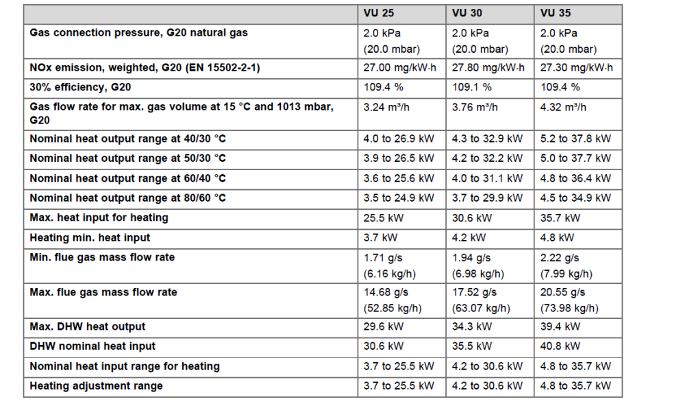
This is from the Ecotec Plus 630 It does show +100% efficiencies based on "30% Efficiency, G20" whatever that means, but more significantely it gives the nominal heat input and the DHW output in kw, all these give efficiencies < 100% at 96.73%, 96.61% & 96.57%, don't know if nominal is based on the LHV or the HHV but suspect its the LHV, so based on fully condensing but a bit of a nonsense as the flue gas temp would probably be ~ 80C, (with little or no condensing), assuming a combustion air temp of 20C then the sensible heat loss is ~ 4.5%*60/100, 2.7%, gives 97.3%.
-
I seem to remember that the gas analysers reported the efficiency based on the LHV when condensing boilers appeared, of course what must be remembered is that they are still ~ 7/8% more efficient (in a nonn condensing state) than a non condensing one because they knock more sensible heat out of the flue gas by reducing it by 120/150C more.
-
Vaillant EcoTec Plus 630 dT
John Carroll replied to John Carroll's topic in Boilers & Hot Water Tanks
Thanks John @JohnMo but too late as I've exceeded my 30 minute window to edit, I know how to it now though!!. -
Sorry John, Don't know as I just read a lot about Evohome in Automated Home.
-
Vaillant EcoTec Plus 630 dT
John Carroll replied to John Carroll's topic in Boilers & Hot Water Tanks
Some one might do a few tests on one of these boilers, @ j_s ? The Boiler is dispatched with (Hydraulic Operating Mode) D.170 set to 2 (dP constant) and D.171 (target pressure value set to 200) If so, or whatever mode your boiler is on, Note D.015 (pump speed), D.029 (flow rate), D.040 (flow temp), D.041 (return temp) and Target Modulation. Change D.170 to 3 (Spread dT), Set D.172 to 20C (Target spread value), take another set of readings after say 10 minutes. If using Weather Compensation, switch it off if possible, set the Boiler Target Temp to 62C , wait for say 5 minutes after target temp is reached and take another set of readings, (D.170 set to 3) Please state if a LLH is installed or not. -
Where are you seeing this efficiency figure?, I didn’t come across it in the MIs. What you can do is something like these tests, ensure boiler/system up to temperature. Test Results. (calculations, in brackets) Target Modulation 78% (boiler output (0.78*30,23.4kw) D.029 Heating flowrate 1575LPH. Flow/return temps D.040/D.041, 62C/47C. (Boiler Output 1575*(62-47)/860), 27.47kw. This consistently shows ~ 10 to 18% higher output than that from target modulation, which I presume is the actual % boiler output. Gas meter readings were taken exactly 3 minutes apart and the consumptionX11x20 to give the energy input in kw, cant find the figure now but it gave a efficiency of 91% based on the target modulation but 106% based on the flow & dT, so maybe that’s where Vaillant are getting their efficiencies from. When/if you do these tests, compare them with the Vaillant figure, might be interesting. I would appreciate if you would carry out the tests sometime as requested and post them in the more appropriate Topic , “Vaillant Ecotec Plus 630 dT” Thanks. John
-
That's Net Efficiency based on the lower heating value of the fuel, natural gas wet gas loss is around 10% to 11% and to attain a true 100% efficiency would require the flue gas temperature to be as low as the combustion air temperature IMO.
-
Honeywell don't pay much attention to these findings since their Evohome continuously cycles the boiler and even smart roomstats with TPI? control do similar.
-
Maybe something a bit like Ideal Vogues "Super Efficiency" ??, this was their reply to someone who was seeing very "poor" efficiencies of less than 65%, at least Ideal arn't claiming 100% +. A bit off topic but is your boiler their latest offering of the 630 where you can run in one of several hydraulic modes, one of which is temperature spread?

-
Came across this in some old book from long ago where it states that "The height of the vent above the CWSC (water level) should be 4% of the head from the bottom of the HW cylinder to the CWSC water level + 150mm" This obviously refers to water at 100C as the expansion is 4% (or very slightly higher) when heated from 15C to 100C. If its easier, 40mm per 1M head can be used instead. (40/1000=4%) My HW cylinder, like a lot of others is installed in the hot press on the landing with the CWSC in the attic, water level ~ 3M above the bottom of the HW cylinder. The theoretical height of the vent should be (3*40)+150, 270mm, if the cylinder was located downstairs with say a 5M head then the vent height should be (5*40)+150, 350mm My vent is 350mm above the CWSC water level but I have seen several where the vent is resting on the CWSC top and ~ 100mm above the water level. Someone asked me years ago why the above vent height is required and I reall don't know. Its not a expansion allowance, my 135L CWSC measures 450mm from the bottom to its normal level so, 3.33mm/L, I have a 150L HW cylinder which would expand by 6L if heated from 15C to 100C, a rise of, 6*3.33, just under 20mm (vent pipe level will rise by the same amount), a long way from the overflow. even a 300L HW cylinder with a expansion of 12L at 100C would still not reach the overflow as the level would rise by, 12*3.33, 40mm, still leaving ~ 50mm to overflow. Of course, normally the HW cylinder never reaches these sort of temperatures.
-
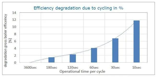
If you can believe the below, then any run time of more than 3 minutes per cycle has a negligible effect on boiler efficiency.
-
There's bags of headrom there to do that, its amazing that none of the plumbers spotted that, that's just basic stuff, you could do that yourself in less than hour. Did any of the plumbers look up there in the attic?.
-
Lowering the level in the cistern is the same as increasing the height of the vent pipe above the water level, if the present height of the vent (where it turns down) above the water level is say only 0.25M and the water is just dribbling then it means that the imbalance or differential pressure across the H is 0.25M, so increasing the distance beteen the waterlevel and the top of the vent by either raising the vent pipe or lowering the water level should have the same effect IMO, rem its a U tube we are talking about, anyway there's reall nothing to be gained with this cistern.
-
Do the LEDs flash when changing modes/settings, don't know if this is for your particular pump or not but its showing pulsating LEDs in PP or CP mode?

-
Do those PP tests anyhow.
-
Anyone who is interested in PP settings can do their own calcs here, you can just put in your own pump PP settings. UPS3 PPs Extract.xlsx
-
That changes things a lot because any blockage in the H now only has only to produce a U tube imbalance (differential head) of that "few cm" to get pumpover, reasons are becoming clearer at last. The combined vent & cold will almost certainly stop that but would still like to see that vent raised a little, alternatively, as a real combined vent&colf feed doesn't have an vent rising over the level of water in the F&E you can just use the cold feed and cap the vent at the H, (install a thumb vent there instead) BUT the cold feed I think, by the regs must be 22mm or more with no isolation valve, boiler must have o/temp proection as well, which yours has. So you couldn't use the existing cold feed but you could plump the existing vent into the F&E and remove the existing cold feed and install a thumb vent there, (or one of those horrible AAVs), personally, I prefer my type but you just may not be able to rise your vent even say 0.5M?. Edit: Can you post a phot of the F&E cistern + water level, you may be able to lower the level in that considerably to give a little extra head, the level only needs to be 80/100mm, expansion will only rise it another 10/15mm.
-
The PP tests should qualify this, if you assume a present flowrate of ~ 15LPM at 3.7M (CC1) then PP2 will give a flowrate of 11.7LPM at 2.25M and PP1 will give a flowrate of 8.2LPM at only 1.15M. The minimum PP2 head is 1.7M & the minimum PP1 head is 1.0M so even if there is almost a full restriction in the H, there cannot be pumpover (assuming vent ~ 2M above F&E cistern water level) at PP1 and practically speaking no pumpover either on PP2, otherwise the pump is faulty. All will be revealed.
-
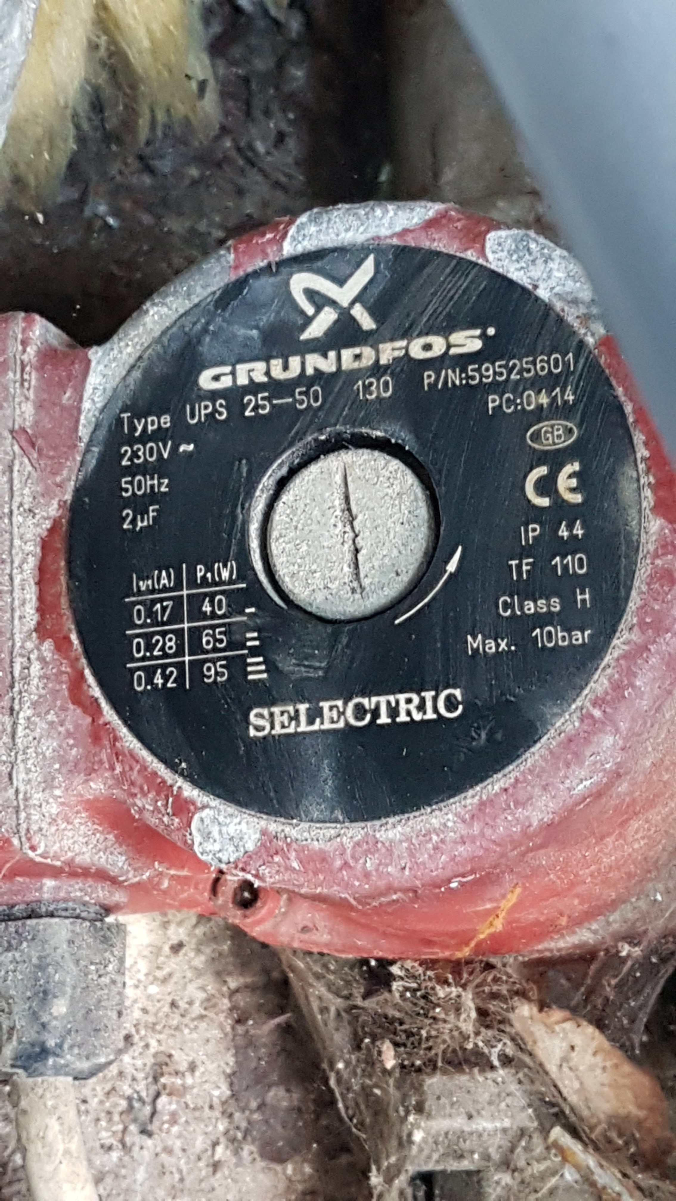
That pump is a relative youngster, PC0945, week 45 2009. My daughters is PC0414, week 14 2004, look at the way its installed! Upright! and still running perfectly, don't know when Grundfos manufactured the cobweb though.

-
You could check the H (but requires a bit of care) by installing a isolating valve (if not allready) on the F&E cistern mains supply to the ballcock, make up a few fittings and attach a hose or whatever to the vent pipe end, shut the pump inlet valve and carefully crack open the mains to see what kind of flow you are getting through the H and back into the F&E cistern.
-
If you can do the H yourself then, as you say, why not, at least you will get great satisfaction once you prove it one way or the other.