John Carroll
-
Posts
577 -
Joined
-
Last visited
-
Days Won
3
Everything posted by John Carroll
-
You can check it again tomorrow or sometime when it settles down. Based on the above, the rad output(s) is 0.4*16.666*60*(28.9-20.4)/860, 3.95kW
-
How many rads in use? and what is/was the boiler flow/return temperature(s).
-
Very good, on any PP setting, does the Evosta3 show the actual pump head?. (as well as the flowrate & power). I have the Rolls Royce of PP & CP settings on my Wilo Yonos Pico where the settings can be incrementally changed in 0.1M steps to give almost infinite "control" but the head is only displayed while its being changed, no big deal really but nice to have displayed if available.
-
Where can/do you see the max/min settings for all the 6 PP settings?, the manual only shows the 3 standard PP settings data?. Anyway if you can see it somewhere just change the settings in the spreadsheet.
-
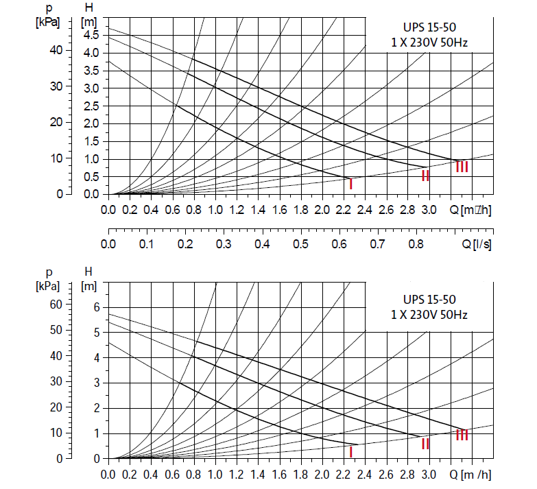
DAB Evosta-2-3-Installation-and-Operation-Manual_UK.pdfDAB Evosta-2-3-Installation-and-Operation-Manual_UK.pdf The standard (3) PP settings are the ones I'm looking at, you have to press the setting button for 20 secs or so i think to get the advanced (6) PP settings. You can see by my trusty spreadsheet that it looks like PP2 will give a flowrate of 0.4m3/hr ish @ 1.95M Dab Evosta3 PP2.xlsx
-
Try PP2 which may by my calcs may give a flowrate of just less than 0.4m3/hr at 1.9M.
-
Immersion thermostat keeps tripping
John Carroll replied to Little Clanger's topic in General Plumbing
Voila!!, If not singing Voila, have you checked that the bottom stat works OK in the upper immersion?. "I swapped the thermostat for the one from the upper immersion heater, but that tripped at some time during the night" -
Immersion thermostat keeps tripping
John Carroll replied to Little Clanger's topic in General Plumbing
Just wondering why a thermostat module that works in the upper immersion should trip due to apparent over temp in the bottom even if the (bottom) heating element is faulty. -
Immersion thermostat keeps tripping
John Carroll replied to Little Clanger's topic in General Plumbing
Is the hi limit stat part of the control stat or a separate stand alone stat?, whether or which, ensure the (normal) control stat setting is not higher than, say, 70C, normally set to 60/65C, post a photo. -
Immersion thermostat keeps tripping
John Carroll replied to Little Clanger's topic in General Plumbing
You say the thermostat keeps tripping, do you mean the lower immersion is tripping the RCD (earth leakage trip) or that the hi limit stat is just switching out the immersion and requires resetting?. -
A rad(s) flow of 0.5m3/hr, 8.33LPM, with flow/returns of 32C/25C will result in a boiler demand of, 8.33*60*(32-25)/860, 4.06kW, say 4.1kW, if the boiler's minimum output is > this then no cycling, if less, then to increase the rads demand/boiler output means either a greater flow, more noise as higher head required or increasing the flow temperature.
-
When you say (Evosta3?) speeds 1&2, which mode are you in, both CP2 & PP2 will have similar outputs at both settings but FS (fixed speed) 2 will draw ~ 21W at a flowrate of 0.5m3/hr and will draw 9W closed valve power. The Selectric, if I have the correct pump curves will circulate 0.48m3/hr @ 2.76M speed1, 0.55m3/hr @ 3.63M speed2 and 0.59m3/hr @ 4.18m speed 3, all close if using a evosta benchmark of 0.5m3/hr @ 3.0M. Selectric 5M
-
What is the exact model of your old Grundfos??. If it is a A rated pump (or not) we can then compare the various modes/settings with the DAB. What model/setting was/is the Dab Evosta3? on to give you 14W, 3.0M, 0.5ms/hr According to its pump curves, the Evosta3 in CP2 (constant pressure) mode will give a flow rate of 0.5m3/h at @ 3.0M head but requires 16W, in CC2 (fixed speed) mode it will only flow 0.2m3/hr @ 14W and also 3.0M, a bit strange.
-
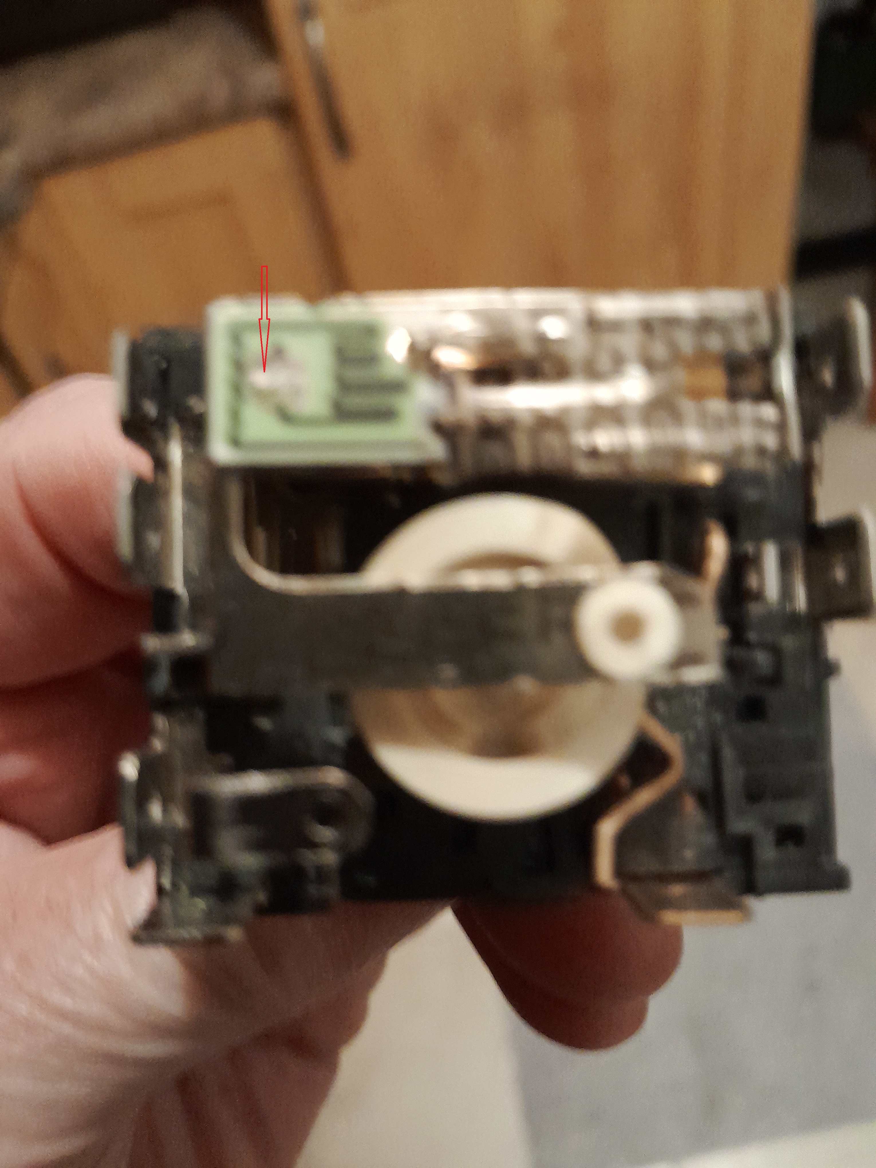
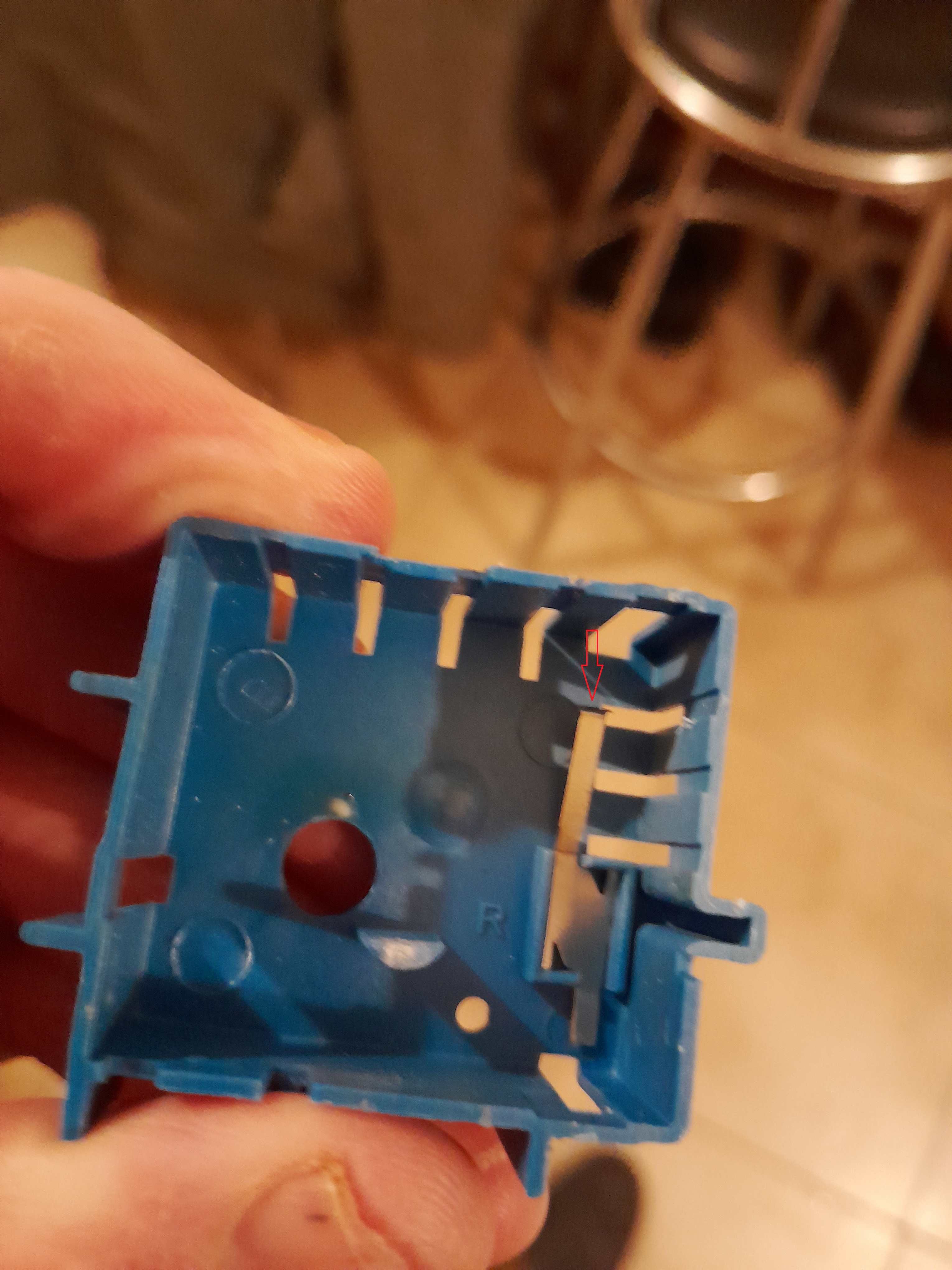
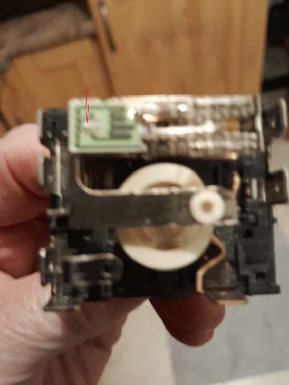
I have a 2008 Belling 90E cooker which uses MP-V01-SVC simmerstats, original manufacturer, Invensys. These have a relativey short life of ~ 2/2.5 years. I never see any complaints re this short life as this type of simmerstat must be widely used, wonder is this a fairly typical lifespan?, only 2 people in this house. I had a Creeda Cavalier for 20 years or more cooking for a family of 5 with not one simmerstat failure. I opened one (failed) up today, and can see that the PCB eventually wears down where the baynot strip end in the cover contacts it due to the very slight pivoting movement of the 5W heating element/bimetal strip as it opens/closes, (rises/falls) the main contacts, the element will then heat continuously as the 5W heater stops working, until switched off. Most of the cookers I see in Spain don't use this system, the elements have several spirals and are switched in directly by the control switch. Look at the red arrows in the attached, if interested.

-
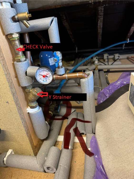
Also, check direction of the arrow on the side of this check valve.
-
Its here.
-
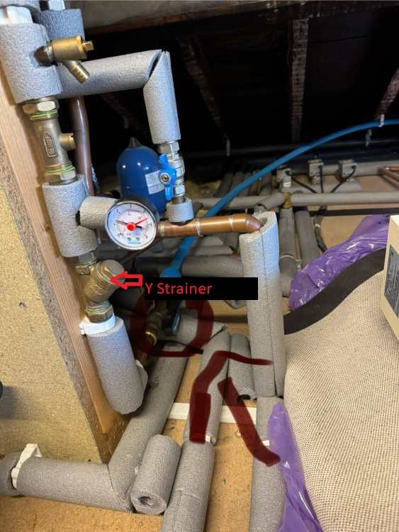
Really don't know what's going on there. Maybe the PRV (pressure reducing valve) on the third? floor is jammed almost fully shut, its set to 1.5bar which means it should have gone fully open at any downstream pressure slightly lower than this, suggest adjusting it to it max setting, whatever that is and see what happens, the Y strainer near it should also be cleaned and the check valve should be removed in case its jammed shut.
-
I think you said 3 floors up?, say 8M, 0.8bar anf if the outside tap pressure was still reading 1.9bar dynamic at a flowrate of 5.2LPM then the pressure drop upstairs is (1.9-0.8)-0.6, 0.5bar. Maybe repeat this test if you havn't observed the outside tap pressure during this last test. its most unlikely that you have two mains supplies from the "road" so also maybe do another test where you open multiple taps to give a total flowrate of ~ 10 to 15LPM, then see what the outside tap pressure falls to during this test, that should give a good idea of the mains supply pressure drop.
-
Also check to see if those two "frozen" pressure gauges change during that test.
-
Vaillant EcoTec Plus 630 dT
John Carroll replied to John Carroll's topic in Boilers & Hot Water Tanks
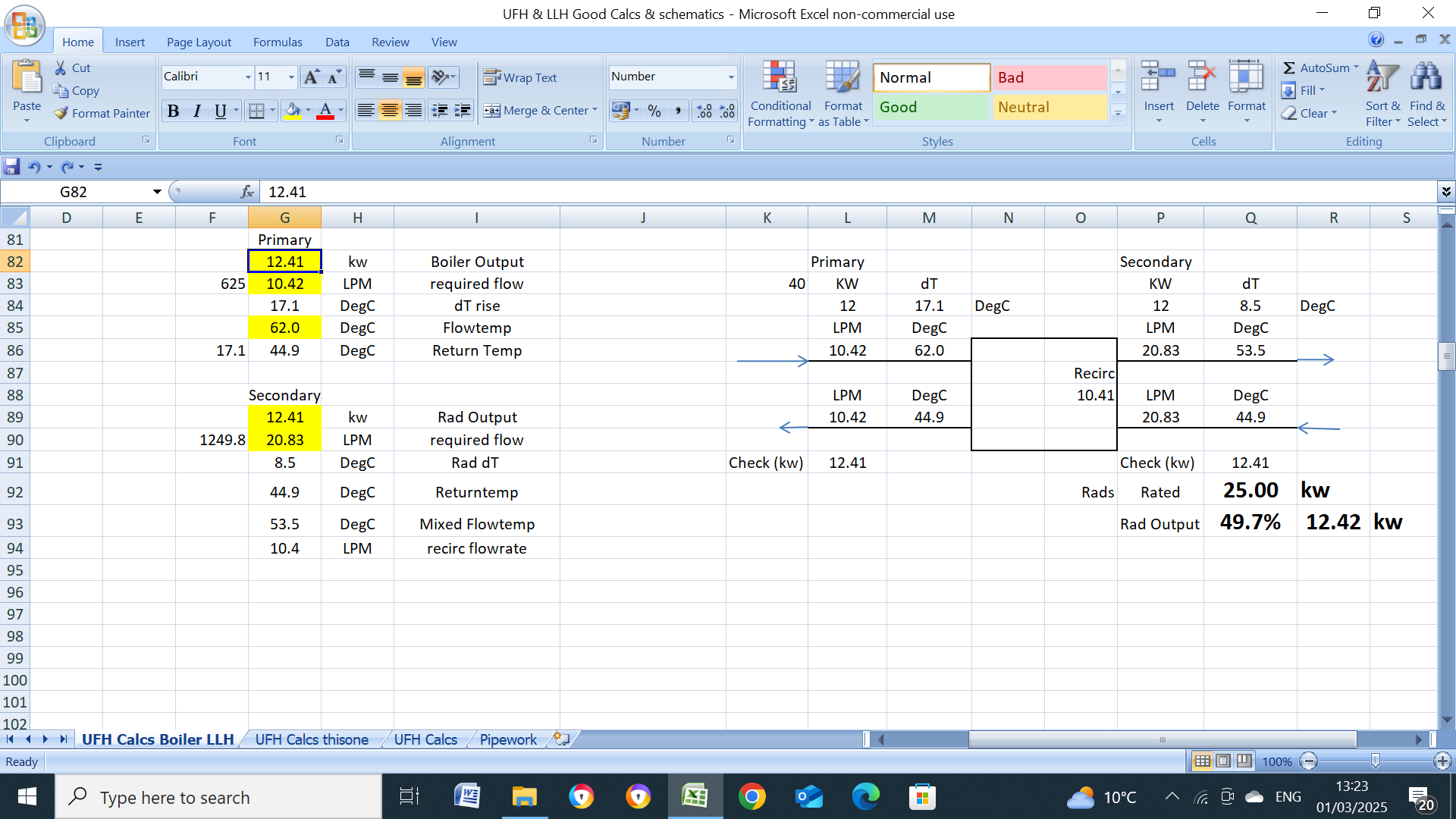
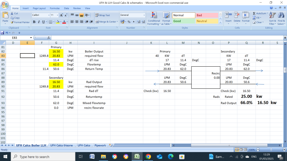
The big danger to rad output is if the secondary flowrate is higher than the primary for whatever reason, see below. the rad output is 16.5kW if both flowrates are 20.83LPM but only 12.4kW if the secondary flowrate is double that of the primary.
-
The pump digital display reads the pressure whether its on or off?, if so, identify some tap(s) hot or cold that are fed from the accumulator, with pump off, open one of these taps until the pressure stops falling, suggest a bath tap, if installed, as these normally give a high flow, note the pump pressure (pump off) and do that 30 sec test again with the bath tap, then shut it and see does the pump pressure rise (pump still off).
-
Vaillant EcoTec Plus 630 dT
John Carroll replied to John Carroll's topic in Boilers & Hot Water Tanks
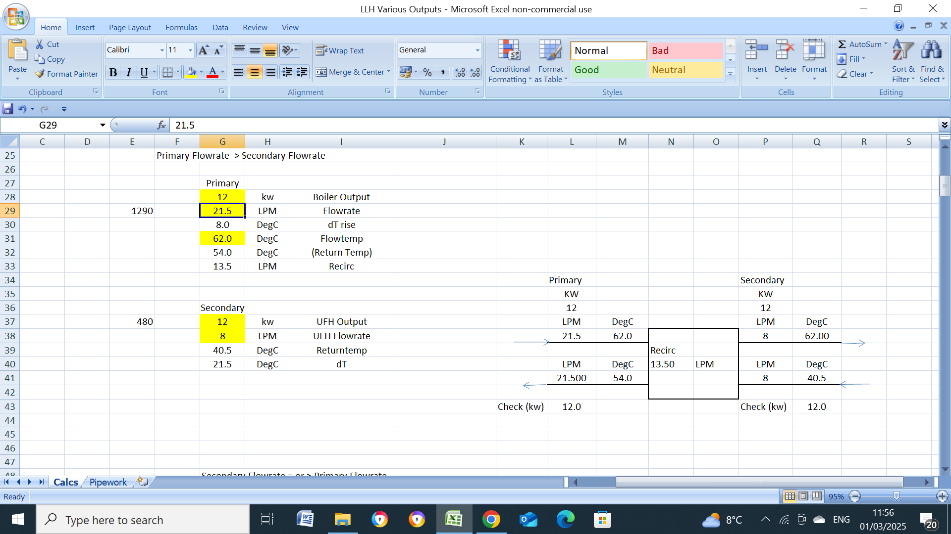
THe main and only reason in the above case is that because the boiler circ pump head/capacity is too low to circulate the water at 21.5LPM through both the boiler HEX and the system. With the LLH, 80% boiler pump speed will/should circulate 21.5LPM through the boiler HEX and the secondary circ pump will circulate 21.5LPM through the system at ~ 7.0M head. Without a LLH then the (6M) boiler circ pump wll only circulate ~ 15.7LPM through both the HEX and the system. If the(with a LLH) boiler circ pump speed is increased to 100% then ~ 4.8LPM will "short circuit" from the boiler flow to the boiler return, rising the return temperature a little. If UFH only on and the primary circ flow is still 21.5LPM with the flow/return to the UFH manifold at only 8.0LPM then a huge short circuit of ~ 13.5LPM which raies the return temperature considerably but if the primary flowrate was reduced automatically by reducing the pump speed via dT control then the boiler return temperature will be considerably less.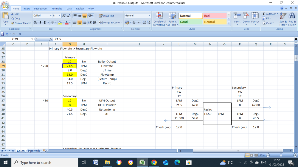

-
Vaillant EcoTec Plus 630 dT
John Carroll replied to John Carroll's topic in Boilers & Hot Water Tanks
Don't think so John, its the opposite, the primary side will satisfy the secondary side flowrate, the remaining primary side flowrate will recirculate on the primary side to raise the boiler return temperature? -
Vaillant EcoTec Plus 630 dT
John Carroll replied to John Carroll's topic in Boilers & Hot Water Tanks
This system boiler & LLH replaced a heat only Vaillant which had a 8M UPS 2 pump, a 140W giant of a pump which will circulate 52LPM @ 8M, 46LPM @ 7M & 35LPM @ 6M, there are 21 rads + UFH (+HW cylinder) and the pump had to be run at a 8M head to satisfy all the rads, so a toss up I suppose to go for the same set up or the system boiler with the LLH. The UPS 2 was installed on the secondary side of the LLH and satisfies all requirements at a 7M head, (and sometimes at 6M), the LLH takes care of the circulation through the boiler HEX which has a pressure loss of 2.6M @ the boiler's rated output of 30kw and flow of 21.5LPM at a 20C dT. The system is often run on UFH only for long periods but because of the above problems then the return temperature is 54C (flow temp 62C), if the dT control was working properly then the dT could be set to the flow temp minus the UFH return temp of ~ 42C, so to 62-42, 20C, or somewhere in between, to give excellent boiler efficiency with a boiler return of 42C, unfortunately, this isn't happening. On UFH only the (primary) boiler pump runs at 80% speed with a dT of (62-54) 8C on dT control, the lowest setting on fixed speed is 50% which does give a improved dT of ~ 12C with a boiler return of 50C. -
Vaillant EcoTec Plus 630 dT
John Carroll replied to John Carroll's topic in Boilers & Hot Water Tanks
Vaillant's final response to the Ecotec Plus 630 problems is despite supplying them with the result the latest tests, below, control works fine in fixed speed mode but not in constant speed mode, not to mention the temperature spread, (dT) mode, where it makes little or no attempt. The Vaillant supplied LLH, below, is, to the best of my knowledge installed correctly, the tests were carried out on CH only where a energy monitor on the 8M UPS2 showed a almost constant flowrate of 1250LPH, 20.83LPM. @burgessl tests on his 625, (NO LLH), showed the controls working more or less as designed in dP constant pressure mode and reasonably close to a set dT of 20C when set in temperature spread, dT, mode with flow temperature set to 62C. It would be very interesting if someone else with either the 625 or the 630 model with a LLH could do some tests.