


John Carroll
-
Posts
577 -
Joined
-
Last visited
-
Days Won
3
Everything posted by John Carroll
-
Ensure pump off, re attach the pressure gauge, note the pressure, start the pump, note the pressure, after say 5 minutes, switch the pump off, again note the pressure. Also note the pump head/pressure while running. With pump off, open kitchen cold tap fully, then wait about 10 minutes, run it into a container for exactly 30 secs, measure this with a 1 litre container, X 2, to give the flowrate in LPM. Note pressures before and during test.
-
Traditionally-styled low temp radiators?
John Carroll replied to YodhrinForge's topic in Central Heating (Radiators)
Well, using the "1.3" exponent, a T25 rad will emit 41% (of a T50) at a flowtemp of 47C, but the rad, a T18.6, will only emit 28% at a flowtemp of 40C (HP max?) and at a flowtemp of 25C, a T4.8 rad, will only emit 5%. Condensing Calcs Extract Gar Rev0.xlsx -
I think its vital, before making any decisions, to get as much data as possible, expecially those two pressure gauge readings, more importantly, the lower one to see what the pump suction pressure is, its no good installing a second accumulator if the mains cannot supply the minimum pump suction head required. Would suggest getting you'r plumber to get these gauges "working" and clean the Y strainer. As stated previously, 1.5bar/2.2bar precharge/charged pressures will give a (300L) accumulator output of 65.63L (present output?), if the charged pressure was at its design of 3.0bar then you will get a increase of over 71% to 112.5L, it might/would require a new charging pump but a charged pressure of 3.5bar will give a increase of over 100% to 133.3L and 4.0bar will give over 128% increase to 150L, as much as adding another 300L accumulator with a charging pressure of (both) of 2.33bar.
-
Traditionally-styled low temp radiators?
John Carroll replied to YodhrinForge's topic in Central Heating (Radiators)
Yes, but if you take the example of a T25 rad (above), this will give 41% output of a T50 but will require a oversize factor of, 1/0.41, X 2.41, to give a T50s rated output and so on. -
Traditionally-styled low temp radiators?
John Carroll replied to YodhrinForge's topic in Central Heating (Radiators)
I've no idea really, it was only years ago when I was looking at the manufacturers correction factors that I realized the ^1.3 "fitted" best. Its a bit strange I suppose that while heat loss is linear, rad output isn't, presumably this is why they have a WC "curve". Re your own correctIon factor above, (60-40)/40-20), presume you mean (60-20)/(40-20)? to give 2, you say you added another ~ 2, X 4 in all?. -
Traditionally-styled low temp radiators?
John Carroll replied to YodhrinForge's topic in Central Heating (Radiators)
To the power of 1.3, see above. -
Traditionally-styled low temp radiators?
John Carroll replied to YodhrinForge's topic in Central Heating (Radiators)
There's a big difference in output between running a rad with a flow temp of 40C and a T40 rated rad A T50 rated rad (now the standard) often has 75C/65C/20C printed on the top of its spec sheet, is the mean rad temp - the required room temp, the mean rad temp is the (flowtemp+returntemp)/2 and 20C is the most often quoted required room temp, so the T50 rad above is ((75+65)/2) -20, 70-20, 50C, a T50 rad. A dT of 10C will require a flowrate of 1.43LPM/kW If the flowrate is kept the same then a T40 rated rad will have, flowtemp/returntemp/dT/output, 63.73C/56.25C/7.48C/74.8% but if that rad is run with a flowtemp of 40C (same flowrate) then these numbers become 40.0C/37.23C/2.77C/25% A T25 rated rad numbers are 47.03C/42.97C/4.06C/41% but if run with a flowtemp of 25C then these numbers are 25.0C/24.53C/0.47C/4.7%. One might thik that a T25 rad would give 50% output, (25/50)x 100, but it doesn't, it gives (25/50)^1.3 x 100, 41%, similarly a T40 rad will not emit 80% of a T50 rated rad, it gives, (40/50)^1.3 x 100, 74.8% -
Thanks, did/can you do the pressure gauge checks and the flow rests.
-
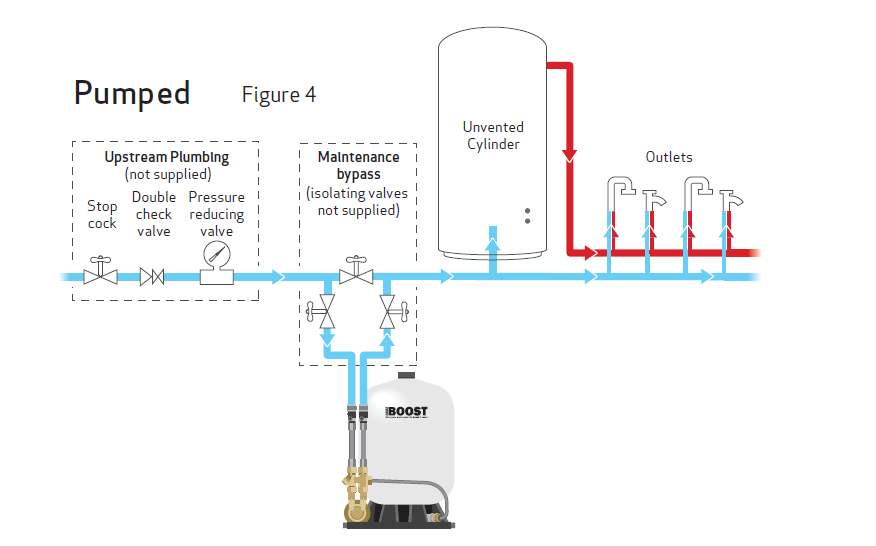
Try and do this please . Typical Pumped Installation below
-
Suggest cleaning the Y strainer and removing the two pressure gauges, (ensure they then read zero pressure) ensure tapping points clear then replace them. With pump off run a "high" flow hot tap only, like a bath tap, if installed, run the hot tap into a bucket/container for exactly 30 secs, measure with a 1 litre milk bottle or whatever, X by 2 to give the flow rate in LPM, note the two pressure gauge readings before and during test. Then start pump with tap still open, throttle the tap flow until the pump pressure is close to 2.0bar, then again note repeat the flow measurements, again note the two pressure gauge readings before and during test. That should/might give enough information on how to proceed.
-
I estimate that you have a 300L accumulator, A precharge pressure of 1.4 bar and a charged pressure of 2.2bar will give a available accumulator vol of 75L, two taps running for 15 mins to use up this 75L gives a combined flowrate of 5.0LPM, (not a lot). It took the pump 37 minutes to recharge the accumulator with, theoretically, 75L, gives a pump flow rate of 2.03LPM, no good. Have you any idea of the flowrate from those two taps before the flow rate fell off. Its very difficult to tell whats happening without a accurate schematic of the pipework. You will see a round plastic dust cap right on the very top of the accumulator, unscrew or prise this off and you should see a (schrader) valve exactly like your car tyre valve, you require a tyre type pressure gauge to check this pressure with the accumulator fully drained. Before considering doing this, or getting it done, with the pump running and no water demand, press down the (schrader) valve pin with your finger nail, if air comes out, diaphragm OK, if water comes out for more than a few seconds then diaphragm knackered.
-
Double post.
-
The above temperature is 1/2 way up the tank. Does this temperature probe also control the heat pump/heating coil on/off?, normally the cylinder stat/control probe is installed say 150mm or so above the bottom of the heating coil, then depending on the coil dT (which depends on the flowrate etc) the temperature at the cylinder top might be ~ 10C higher than at the "bottom" so maybe 5C or so at mid point but if the control is from midpoint then less of a gradient. where are the coil inlet/outlet connections? and what is the HP flow/return temps and flowrate with cylinder heating only on?.
-
Will read back the posts sometime but was that H actually opened up?. A relatively small system leak could also cause these problems with sludge etc but would require tying up the ballcock on the F&E cistern for a day or two and then see if there is makeup when released. I have a isolating valve on the make up and only open it every few months for a min or two to check for leaks.
-
Well, I think what I have learned from this thread is that the first port of call should be to ensure that the vent is installed properly, ie, up and over the cistern, even with a perfectly clean H there was bound to be some carry over and aeration with that installation, there are literally dozens of houses around me, some, with the combined cold feed and vent and some with the H, some have never ever had a drop of inhibitor since these houses were built, over 50 years ago, yet some have rads, like my own, 30 and 40 years old. I can only assume that no air is ever entering the system(s) and obviously no system leaks.
-
All because the vent wasn't carried up and over the F&E Cistern originally?.
-
Presume the pump discharge is teed in above this PRV, otherwise the accumulator will only run at 1.5bar, useless, with a precharge pressure of 1.4/1.5bar?., where would/should a check valve be installed?.
-
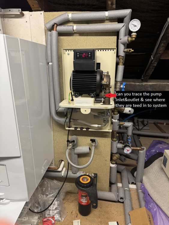
I only saw this photo today. Can you switch off the pump and open a few taps to give a good flow ~ 15LPM and note the two pressures, switch on the pump and note the pressures again, shut the taps and note the pressures as the pump stops. Also check to see where the pump discharge (outlet) pipe is teed in to the system.
-
"Also check for a schrader type valve (like a car type) on top of the accumulator, if there is one, check that pressure with the cylinder fully drained, it should be at or set to whatever D7 is set to (Charged pressure - 0.2bar)." Should be set to the precharged pressure, D7.
-
Radiator Output and DeltaT Correction Factor
John Carroll replied to DREG's topic in Central Heating (Radiators)
Simply put, yes, the specified T60 rad output should, IMO, be 643/0.17212, 3736 watts. Don't know what the corrected loss of 2074 watts means though. -
No problem. First, you know yourself what the minimum pressure you require to give you the minimum acceptable flowrate, so change (cell) D16 "End Pressure" (present setting 1.5bar) to whatever the minimum operating pressure is or should be. Then change D7 "Precharge Pressure" to the D16 setting minus 0.2bar, if you set D16 to say 1.8bar then set D7 to 1.8-0.2, 1.6bar. Change D9 & D18 (both) "Charged Pressure" to whatever your pump is cutting out at, present setting, 2.2bar OR whatever you think it should be capable of. D6 "Accumulator Capacity" present setting 175litres, leave or change it to whatever the actual capacity is, if not known, get a tape and measure the circumference, and the height, post back and a good estimation of the capacity can be arrived at, also state the insulation (if any) thickness. Also check for a schrader type valve (like a car type) on top of the accumulator, if there is one, check that pressure with the cylinder fully drained, it should be at or set to whatever D7 is set to (Charged pressure - 0.2bar).
-
I would get that pump looked at for a start. If that was operating as designed then it should have no problem in achieving 3.0bar could give a 71% increase in the accumulator output, refilling time for a 175L accumulator should still only be 11 ninutes or so. Accumulator 175L Calcs Rev 0.xlsx
-
Radiator Output and DeltaT Correction Factor
John Carroll replied to DREG's topic in Central Heating (Radiators)
What I have all ways used based on the mauufacturers correction tables for mild steel rads at any rate is the exponential 1.3. A 15.5C rad will have a correction factor of (15.5/60)^1.3, 0.17212 to give 285.894 watts from a 1661 watt (T60) rad, or 96.16% of your figure of 297.32 watts. -
Yes, the calcs are correct. Its a bit strange though that the rad outputs were based on a T60 rating which was replaced well over 10 years ago by the T50 standard in the UK, if the rads are actually "T50" then any calculated output(s) based on T60 will be 20% or so lower, shouldn't affect the UFH though. Might also be worth checking the flow/return temps in the bathroom rad to get a proper dT, it may be far greater than 3C.
-
Just looking at the figures for the bathroom, flowtemp of say 39C with dT of 20C? gives a return temp of 19C, a mean rad temperature of, (39+20)/2, 29C, giving a output (T60 based) of ((29-20)/60)1.3, (9/60)^1.3, 8.5%, rad output, 5668*8.5%, 482BTU by my calcs or 141W (not a lot), if the room temp is 18C then the output is (11/60)^1.3, 11.02%, actual rad output 5668*11.02%, 625BTU, 183W?. That dT seems very high for a flowtemp of 39C, would have expected ~ maybe around 8C or so which would increase the rad output due to the higher mean rad temp so ~ rad output of 16.49% to give a output of 935BTU, 274W assuming the room temp rose to 20C.