


John Carroll
-
Posts
577 -
Joined
-
Last visited
-
Days Won
3
Everything posted by John Carroll
-
Noisy Radiators... we have an ASHP
John Carroll replied to sirpatchuk's topic in Other Heating Systems
It states above, "Without PWM signal, the pump runs at maximum speed" so if there isn't another cable plugged into the pump PWM socket and it looks like there isnt, then that pump will be running at a 7M head so can't be set to one of its other heads down to 4 or 5M?. These UPM type pumps seem popular with UFH systems, wonder why, as all the normal type can run in all the different modes/settings. most don't have this PWM socket but its very rarely needed. -
Noisy Radiators... we have an ASHP
John Carroll replied to sirpatchuk's topic in Other Heating Systems
Unless this pump has a external (PWM) signal then it will only run at the highest speed, a 7M head. This will more than likely cause noisy operation IMO especially when coupled with Evohome control which continually throttles the motorized rad valves, don't know what the cure for this is.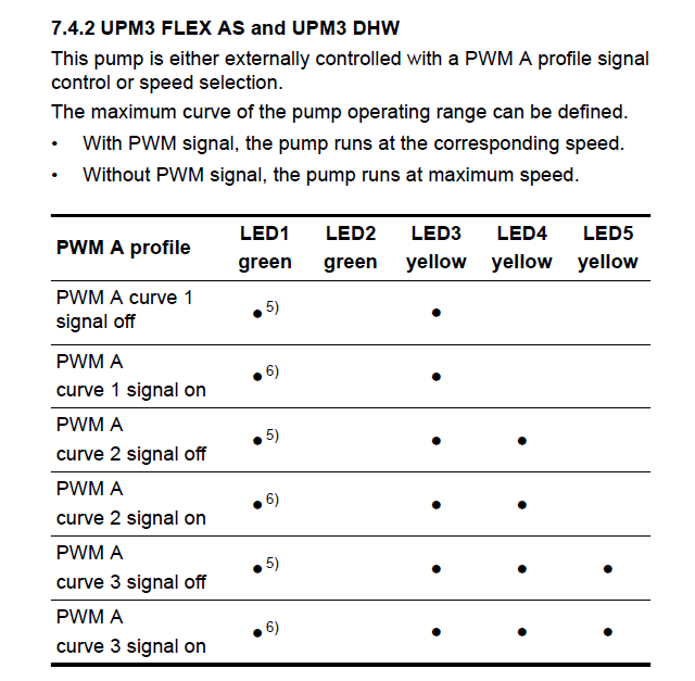
-
Weather Compensation for Radiators only and UFH only
John Carroll replied to John Carroll's topic in Underfloor Heating
UFH by its very nature has to run with relatively low temperatures to avoid damage to floor surfaces, so is sized accordingly, Rads are sized on a T50 basis so a required room temperature of 20C would require temps, flow/return/dT, of 75C/65C/10C at whatever the lowest OAT they were sized to. Most of my own would just about deal with a OAT of -10C, consequently I would need to oversize by a factor of at least 2 even with at a OAT of 5C or so and by a factor of 2.5 at a OAT of 0C to enable running with lowish ASHP temps, see attached. ASHP WC Extract.xlsx -
Weather Compensation for Radiators only and UFH only
John Carroll replied to John Carroll's topic in Underfloor Heating
Came across this sometime/somewhere where some one was (ASHP) running their rads on WC of 43C@-10C & 35C@15C, must have had mighty big rads, if I ever installed a ASHP I reckon if I installed a extra rad in 3 downstairs rooms the I could probably run reasonably comfortably with a more aggressive WC slope. ASHP WC.xlsx -
Noisy Radiators... we have an ASHP
John Carroll replied to sirpatchuk's topic in Other Heating Systems
Can you identify which pump is serving the CH (rads only) by just requesing rads only on and then take a photo of the front of the pump showing its LEDs, which should show what head the pump is producing. -
Noisy Radiators... we have an ASHP
John Carroll replied to sirpatchuk's topic in Other Heating Systems
In another thread you also had a Grant ASHP 17 KW, did you have noise while this was installed or is it at another location? -
Can the same temperature compensation models be used for the above, ie a house with Radiator heating only and another house with UFH heating only. In the attached Vaillant WC Curves, one might use Curve 1.8 with radiator heating where a rad temperature of 70C might be required at -5C but use say Curve 0.6 with UFH heating where a UFH flow temperature of 42C might be required at -5C. Can some one post their UFH WC curves please. Vaillant Weather Curve.docx
-
Noisy Radiators... we have an ASHP
John Carroll replied to sirpatchuk's topic in Other Heating Systems
Well, any flowrate up to ~ 5 LPM with both rad valves fully open, should not be problematic, IMO. Assuming a flowtemp of 42C then the rad output will be 33.4% of a T50 with a dT of 0.95C, if it is running with a dT of 5C then its output is 29.4% of a T50 with a flowrate of 0.84LPM. If it is running with noisy operation at say 7.0LPM then its output is 33.7% of a T50 with a dT of only 0.68C. These numbers are all based on a 1.0kw, T50 rad. -
Noisy Radiators... we have an ASHP
John Carroll replied to sirpatchuk's topic in Other Heating Systems
Have you smart radiator valves controlled by Evohome or such? Check circ pump settings and post its make/model/mode/settings and flowrate if it displays it. Check UFH manifold meter settings (throttled etc) and flowrates. Does one circ pump serve the rads and the UFH? Where is the expansion vessel located?. -
https://www.wolseley.co.uk/product/neomitis-2-port-zone-valve-22mm/?srsltid=AfmBOoqv_ENIV53nUqWT0o_kPleTlp7Vrj29abrEn4EMV9R9BhMx7LT7
-
This might be of interest as it shows the effect of the cold feed teed in both before and after the pump, I just calculated the pressures at 4 or 5 points in a system with a loop of pipe, but doesn't matter, the differential pressure through any system is still the pump head. Point of No Pressure Change M Rev0.xlsx
-
That's the valve, below, operates like any 2 port valve, you can see the lever in the Auto position, on the end to the left, when you pull on this you should feel a fairly stiff resistance while pulling it across to the right, when its almost fully over, just push the lever up and let it move back towards the left, the lever will then latch in (up) and keep the valve open, but, as stated above, will not operate the micro switch as its only latched open when draining or refilling the system and you don't want your boiler, that you forgot to switch off!, firing up with no water in it. When energised open the valve will move fully across and engage the micro switch to fire the boiler. If the lever feels loose and floppy without any resistance when pulling across when NOT energised then the actuator is kaput and needs renewing. Another feature of these valves is that if you have it manually latched open say when refilling the system and its then energised, when its deenergised again the valve will close automatically as the lever will have fallen down, out of its latch, when motorised fully across.
-
A boiler flowrate of 0.6m3/hr, 10LPM, with a dT of 10C gives a output of, 10*60*10/860, 6.98kw, with rad(s) outputs of ~ 21% (flow/return, 40C/30C) of their T50 rating. I really can't see any reason for the system to be pulling in air, the distance from the F&E cistern level to the pump is 3.7M and because the vent & cold feed are teed in before the pump suction then the pump discharge pressure will be 6.7M (@3.0M pump head) and irrespective of the pump head, the lowest pressure in any part of that system has to be 3.7M or greater. Try and do that glass test before you go on holiday (and enjoy), IF the vent is pulling in air continuously then very very strange, the obvious one is wrong pump orientation but we know that the pump is pumping upwards. Apart from that, air ingress, over time, can occur through pump gaskets or non barrier "plastic" pipework etc.
-
Thats a nice circ pump, I've installed a few of them in my relations systems. They also show the flowrate in m3/hr, you might post this while running in CC2 (Fixed speed2) @ 3.0M on CH, you might expect to see ~ 0.7/0.8m3/hr, the pump also displays the power in watts (W), please post this as well, How many rads??, Not sure what you mean by the pipe calcs, for every meter change in level in a 22mm copper pipe, 0.32L of water has either to be added to it or removed from it?, IMO. Do you leave the shut off caps on the two (automatic?) vents open allways and do you see or hear any air venting from them?, if you don't leave them open, why not?.
-
Can you post a photo of the pump&pipework as is now? How far is the boiler (elevation wise) below the pump? You might do that glass test again but in a slightly different way which should prove whether the vent is continually drawing in air or not. With the pump running at ~ 3M, only then immerse the vent end in the glass of water and see does the level remain the same. 22mm of copper pipe has a ID of 20.2mm so should have a capacity of 0.32L/M, a " 1 pint" glass say 0.5L, if all the water was sucked out of it on pump start up then the level in the vent must have dropped by 1.6M, or 0.8MM if a 1/2 pint glass, I've read that the level in a normal system falls by ~ 10mm in both the vent&cold feed with a running pump.
-
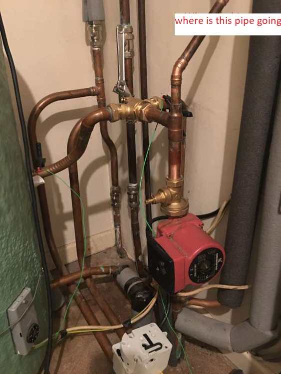
The photo shows either a mid position valve or a diverter valve (with the adjustable spanner), why/how is the F&E cistern only feeding the CH circuit, its teed into the pump inlet?, and whats the other pipe for?
-
Are the vent and cold feed dedicated only as a vent and cold feed?, ie, there are no returns (or flows!) teed in anywhere to either of them. My Vent from the boiler on the ground floor right up to the HW cylinder (on the landing) have all the flows teed off from it.
-
There should be a arrow on the filter body as well, check this is also pointing UP. Is the filter clean?
-
So, the magnaclean, cold feed & vent are all very close to the pump inlet (suction end) and the arrow on the pump body is definitely pointing UP??
-
Yes, something like that. Re your existing set up as per your line drawing, can you give a estimate of the distances starting at the vent.... vent to cold feed, cold feed to filter and filter to pump inlet.
-
Yes and thats why the distsnce between the cold feed and the vent should be kept as little as possible, < 150mm so no pressure loss between the two. Its illogical allright but I have seen systems like yours that display the same problems "cured" by converting to my type, with the two combined as close to the F&E cistern as possible, needs a bit of plumbing though.
VentColdFeed.JPG.5b53a17bb4bad70aa591466343858490.JPG)
-
That looks fine, flow from the boiler outlet (hot) with Vent then Cold feed then Pump?. Sometimes the cold feed where its teed into the flow can get partially blocked and cause problems, can you watch the vent for pump over while someone statrs/stops the boiler/circ pump, also try holding that glass full of water with the vent end immersed in it to see if the level falls. What type of filter is installed before the pump?.
-
I don't get that, you said, above that, "I've got a pump head of 3.0 m but the actual height of the F&E tank water level to the pump is closer to 2.0 m" ?? can you provide a rough sketch also showing where the cold feed is teed in and position of the vent.
-
It depends on where the cold feed is teed into the system, if its just before the pump (suction) then the pump discharge head is the "height"+the pump head, in your case, 2M+3M=5M. If its after the pump on the discharge side then the pump suction head is the height-the pump head, 2M-3M=-1M, pump running with a negative head of 1M. The rad in my converted attic runs with a very slight negative pressure, if you open the rad vent with the pump running then no water comes out but as soon as you stop the pump, water will start bleeding out, its run that way for ~ 30 years with no problems and heats up fully, as stated above, I require a pump head of 3.6M to fully heat all my rads.
-
The only reason I can give for noisy operation now vs with the stove is that the stove probably had a much higher resistance to flow because probably a build up of sludge etc over the years compared with the new cylinder resulting in the pump over on start up & (probably) shut down, is there any possibility of raising the vent pipe higher before it turns down?. I am very surprised still at this pump over with a pump developing only 1.0M head, normal pump head would be ~ 3/3.5M, like mine at 3.6M, same set up as yours, pumping into the boiler return but with a "combined" vent & cold feed, they are combined at the F&E cistern. (but I still retained the vent), I have a oil fired boiler with little or no resistance to flow.
VentColdFeed.JPG.d6b10841c5467515fcba3a284f5d779c.JPG)

