Jeremy Harris
-
Posts
26430 -
Joined
-
Last visited
-
Days Won
360
Everything posted by Jeremy Harris
-

Plumbing - push fit or copper?
Jeremy Harris replied to LeanTwo's topic in General Construction Issues
So was I, until I realised that all the underground pipe on the farm (and feeding pretty much every house built in the past 30 years or more) was plastic and used synthetic rubber seals, and it never seemed to fail. Copper, on the other hand, has given me loads of trouble over the years, especially corrosion when it was fed through holes in granite walls, where it barely lasts a couple of years. If it's good enough, and reliable enough, to be used to supply water and electricity, buried under roads, it's good enough for me. The big advantage in our new build was that with copper I would have had several completely inaccessible joints had I used copper, either in the floor/ceiling void or in the service void in the walls. Leaks could remain undetected for a long time, particularly in the walls, and the damage done to the fabric of the house could have been massive, even for a small leak, over a period of time. Plastic allowed for a layout with no joints at all that were inaccessible. Every pipe joint in the house can be both seen and fixed if there is ever a problem. The continuous runs of pipe in the ceiling and wall voids completely removed the possibility of having a leak in any of those areas (short of drilling a hole through a pipe by accident). -
Help with Completion Certificate on Existing House
Jeremy Harris replied to AliG's topic in Building Regulations
Sounds like the standard solution to this problem. We had an extension where the main roof downpipe ended up being boxed inside a corner of the extension. The building inspector insisted that this pipe be a bit of 110mm soil pipe, so that it had proper seals, even though it was running to a soakaway. I think the logic is that rainwater downpipe never seals properly at the joints, even if glued, and a blockage at the lower end could result in water running inside the extension. -
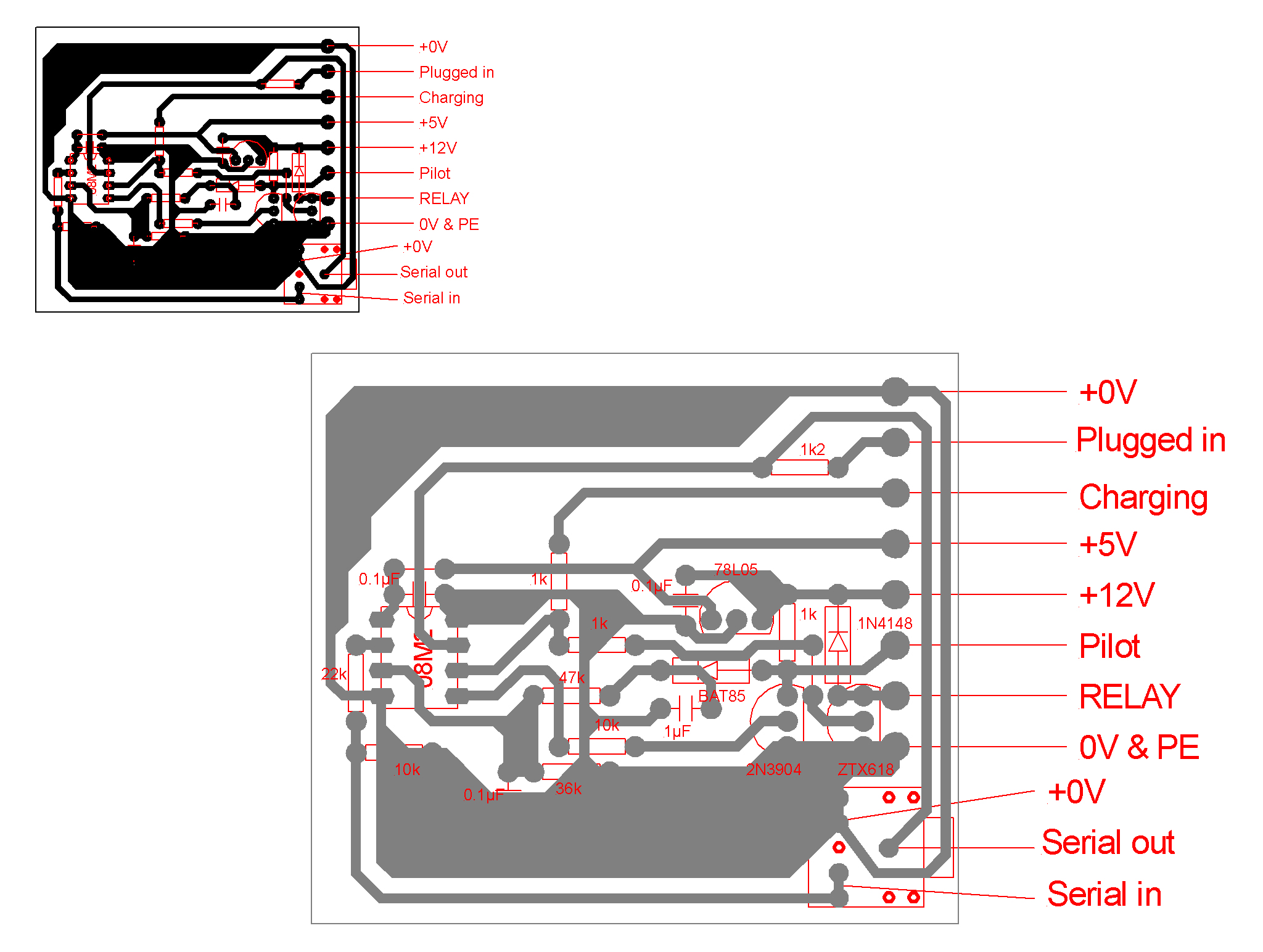
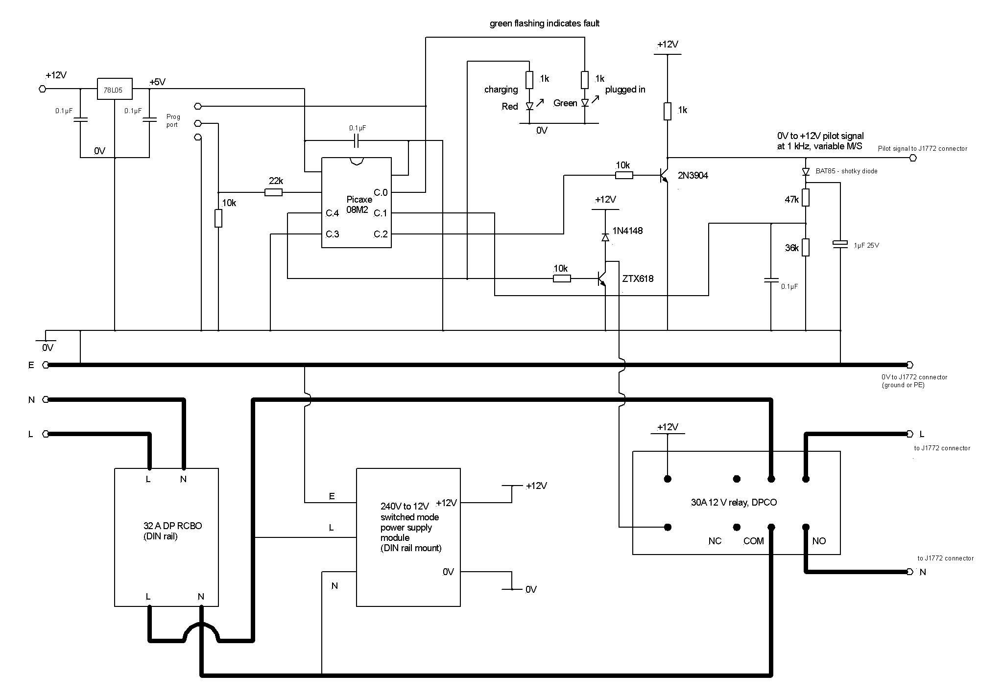
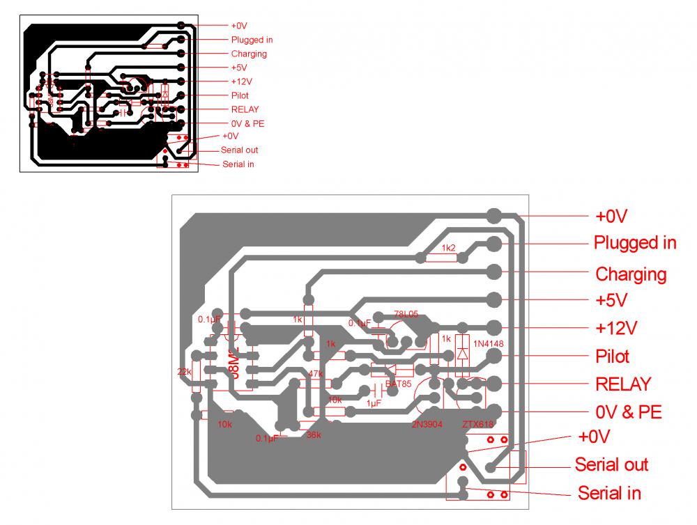
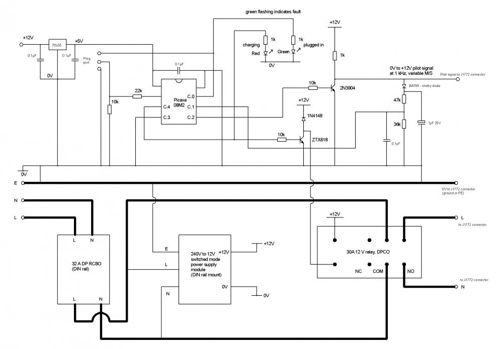
Here’s some more info on EVSEs, a schematic and generic parts list for my basic 15A/30A version (max current can be changed in firmware – the components are all rated for 30 A). First you need a 32 A capable Type 1 plug: https://evconnectors.com/electric-vehicle-chargers-and-accessories/j1772-32-amp-plug-and-cable-ds1-ev32p-nc, unless you are only looking to install a 15 A EVSE, in which case you could look at getting a 16 A plug: https://evconnectors.com/electric-vehicle-chargers-and-accessories/j1772-16-amp-plug-and-cable-ds1-ev16p-nc You can opt to buy the plug and a special 5 core cable, from the same links, but the cable is a bit expensive and you only actually need 4 cores (I’ve never understood why they run both pilots up the cable, as one is either unused or cut off and terminated at the EVSE plug end, if you go for a cable with a plug on both ends). It’s worth making a decision now as to whether you wish to use public charge points, as you can save some money buy making your home charge cable fir both your home EVSE and a public charge point. This costs more for connectors, but there is an overall saving. A 5m cable will be fine for all public charge points that use an IEC62196-2 socket. I’ll assume for the moment that you just want a 15 A or 30 A home EVSE with a tethered lead. If you want to make up your own lead and connector, then 4 core H07RN-F cable is ideal, as it’s very tough and remains flexible in very cold weather. For a 15 A EVSE you can use 4 core 2.5mm², for a 30 A EVSE you need to go up to 4mm² cable. As a guide, this link shows prices from Quickbit, who are generally fairly competitive: https://quickbit.co.uk/cable/cable-h07rn-f-cable/h07rn-f-cable-4-core Terminating the cable inside the Type 1 connector ideally needs the proper crimp tool, but it is possible to solder the cables to the buckets in the pins with care, and there’s plenty of strain relief, so solder doesn’t present a reliability issue. If you don’t have a big soldering iron (the pins are around 6mm in diameter and do need a powerful iron), or a crimping tool, then it may well be better to just bite the bullet and buy a Type 1 plug with a cable already attached. You will need a waterproof consumer unit type box to fit everything into. I use Italian made boxes that have room for the circuitry, and space to take an IEC62196-2 socket on the front, if you want to go down that option. These are on Ebay: http://www.ebay.co.uk/itm/IP65-MCB-RCD-Enclosure-Caravan-Hook-Up-Distributiobn-enclosure-adaptable-box-/251948088117?hash=item3aa946bb35:g:NpAAAOSwd4tUCdfa from 247 Supply, and have enough room to take a 12V power supply, a 32 A DP RCBO, and the circuitry. The relay is mounted next to the PCB in the blank area of the box at the bottom. You can either fit a cable gland at the base of the box to take the trailing lead, or you can just fit an IEC62196-2 socket on the front if you wish to make an EVSE that works like a public charge point, with no tethered lead. There a pros and cons for each option, and I’ve built one of each, at opposite ends of the drive. 99% of the time I use the one with the tethered lead, as it’s quicker to uncoil and plug in. Rapid electronics can supply all the components. The relays I used were Finder 66.82.012.0000 that are rated at 30 A at 240 V, with a 12 V coil. They are easy to fix down with screws. I used an alloy plate cut to fit the back of the box and mounted the relay and circuit board on that. The power supply I used was a Meanwell 12V DIN rail mount one, that has some spare capacity (one on mine also runs a wireless CCTV camera). The model is their DR-15-12, which has the stepped top needed to fit inside a consumer unit type box. The LEDs can be fitted in holes drilled in the spare spacers to the side of the RCBO and power supply, so they can be seen under the clear cover. The code for the microcontroller needs to be programmed in via the serial port connector at the lower right of the board, and is tweaked depending on whether you want a 15 A or 30 A EVSE. The same basic circuit is used for the variable supply unit, but I feed in serial data from a radio link to the unused input port, C.3, so the PCB is slightly different, with that pin broken out, along with +5V and 0V for the serial data radio module. The firmware is also a lot different, as it constantly polls the receiver to get the current state of excess PV generation (if there is any) and adjusts the mark-space ratio accordingly. I can post the code for the basic EVSE later if you feel up to making one, and can easily make a PCB for you and programme the chip. If not, then there are some good kits around at not far off the same price, that don’t need so much DIY. This is one option: http://evbitz.uk/EVBitz.uk/EVSE_Kit_-_Type_1.html that uses the Viridian EVSE module, that has all the control stuff and contactor already built in. These kits will fit into the enclosure I used, and you can choose to just buy the Viridian EVSE controller (http://evbitz.uk/EVBitz.uk/Viridian_EPC.html) and the Type 1 plug and buy your own cable and box. This is the schematic: And this is the PCB layout:
-
Not sure that my 55 deg C max cylinder is significantly different to the conditions and safety systems that the Combi 185 has, though. I think the key here is that Genvex have added enough safety devices to ensure that the integral tank doesn't exceed 65 deg C, plus have added an arrangement of check valves, PRedV and a PRV to cover the case if there were multiple failures. I'm not even sure that the PRV would release any water at all under normal operating conditions, with no inlet side EV. We're guessing that it may do, but in my case that guess is based on experience with two very different systems, the boiler on our boiling water tap, that has no EV by design, as it is intended to maintain a high internal pressure, and my experience fixing a friends electric water heater in France, that also had no EV, but just a PRV. I accept that water waste is undesirable, but I'd guess that even if the PRV does dribble a bit the waste would be less than the evaporative loss from a vented header tank.
-
I have several versions, but the simplest one would be the easiest, as it doesn't rely on the energy measurement system that I have built-in to our supply point (in essence, I have a system that measures the true energy being imported/exported at our external meter box and transmits that data for use by the hot water system and the more sophisticated charge point). I'll post more info later.
-
Strictly speaking it was not signed off, we both reached an agreement that no certification or signing off under Part G3 was required, after having read the intent of the law within the Building Act 1984, as amended to that date. In other words, Part G3 did not apply in this particular case, because it fell outwith the reasoning in law for having the installation signed off, with a commissioning certificate, by a competent person. BCOs have some authority to determine whether, in their view, a non-standard arrangement falls under a particular certification requirement or whether it does not. In my case the intent of the law was clear, the limitations and safety provisions within the system were deemed adequate, and so the system was declared to fall outwith the guidance provided within Approved Document Part G3. The key was whether or not the "pressurised vessel" could ever reach a temperature that could cause a scalding risk if the PRV operated. The conclusion was that it could not, as there was no way for the temperature to exceed 55 deg C under any possible fault condition. I think it's worth noting exactly what the guidance in Part G3 has to say, remembering that it is only guidance, not law or a regulation with the power of law. I've highlighted the wording that makes it clear that alternative approaches are acceptable, if they are deemed to be safe, and that proprietary packages may satisfy the requirements: Note that there is nothing in Part G3, or the underpinning law, the Building Act 1984, as amended, that requires an expansion vessel. That requirement arises solely from Manufacturer's Instructions, not any regulation. The fact that we're used to seeing EVs fitted as a matter of course comes down to a lot of UK manufacturers including them in their MIs.
-
That's my thinking, too. Knowing a fair bit, from experience, as to how Genvex systems are engineered, I'm near-certain that this integrated unit is designed to be safe and compliant with UK regs as it stands, as long as it is installed as per the MIs. If it were a stand-alone UVC, with none of the built in safety systems that the Combi 185 has, then I'd agree 100% with @Nickfromwales, and I think the stand alone UVC where we have to add stuff in the right place order to make it comply with the regs is what we are used to.
-
In addition, you have to agree to your usage data being collected and sent by a mobile data link to the installation company usually. In my case I had a site survey for a "free" installation and the company doing it refused on the grounds that there was no mobile signal available for them to use for data collection................. This was the reason I decided to design and build my own charge points, as I hadn't realised that the grant-funded installers were being given the right to remotely collect usage data, a bit like smart meters.
-
Bear in mind that I'm running a non-Part G3 signed off sealed system, and have been through the hoops on this. If the temperature in the sealed system cannot reach that where there is a scalding risk, because of either design (in my case the same as @PeterStarck, a heat pump that cannot deliver more than 55 deg C even under fault conditions) or built in safety systems, then BCOs can, if shown the regulations (not the Approved Documents) agree that the system doesn't need certification.
-
That is annoying, as around three years ago they were very helpful! One thing has occurred to me. As the electric heating element is, effectively, optional, and as it is only the electric heating element that can cause an over-pressure event if there are multiple control system failures, I wonder if the standard control group diagram is intended to be only for the version without the electric element? Off the top of my head I don't think the tank pressure would increase much at all from cold to 55 deg C, and it couldn't get hotter than this with just the EAHP, as that's pretty much the limit of the system, physically. It may well be that no EV is shown because one just isn't needed when the hot water is only heated from the EAHP, as there is no possible fault condition that could cause the temperature to increase above the EAHP maximum. The EV is fitted to a conventional UVC as a means of preventing very hot water from being discharged via the PRV, because of the scalding risk, primarily. If the temperature is physically limited to 55 deg C, there is no scalding risk from a PRV discharge, as well as the pressure rise possibly being too low to cause the PRV to discharge. Such a system would comply with the regulations here, but is not specifically referred to in the Approved Documents, I think. I remember having this discussion with my BCO over the 58 deg C maximum discharge temperature of the Sunamp PV PRV, and being asked to just put maximum temperature labels on pipes as a reminder to anyone later that this was not a high temperature discharge, so did not carry the scalding risks associated with a high temperature UVC or combi boiler PRV discharge
-
@PeterStarck, it would be worth contacting Genvex themselves, I think, in Denmark. They have a pretty good technical department and were able to quickly answer my question about adding an external hygrometer switch to activate the boost function, and included the additional information that there was some spare 24V DC power available from the connector block in the unit to power ancillary devices. IIRC, I just emailed the contact on this page, in English, and got a pretty prompt reply: http://www.genvex.dk/en/contact/
-
I could do, in fact a part of it is already published, back from when I first designed a DIY charge point, and even back then it had a modulation input that allowed the available current pilot signal to be changed on the fly, as I was thinking ahead to adding the excess PV firmware (and it is just firmware, there's no change to the hardware, just a wireless serial data link plugged in to the board). I don't want to make money from it though, so I'm happy enough for anyone to just copy what I've done if they wish.
-
MVHR pipework camera?
Jeremy Harris replied to readiescards's topic in Mechanical Ventilation with Heat Recovery (MVHR)
I'll see if I can record a bit of video from inside a duct with it. I think it should slide in fairly easily, as the smooth inner lining inside the semi-flexible ducting seems pretty slippery. I have some 6mm nylon pneumatic pipe around somewhere, that should be stiff enough to push the camera, so will try just taping it to that and seeing how it works. -
Beat them to it! My charge point has been using the radio signal that is used to transmit the excess PV generation data to the Sunamp PV to modulate the mark-space ratio of the 1 kHz pilot signal that is sent to the car to tell it what the capacity of the charger is. This allows the car to be charged at a rate determined by the available excess PV, but there is a fundamental flaw, that cannot be overcome with the current car interface standard. That flaw is that any pilot signal that indicates that there is less than 6 A available is invalid - the standard does not allow cars to charge at a current that is less than 6 A. This means that you cannot charge the car below 6 A, as the car charger just turns off if you try to (this applies to all AC charged cars). So, the charge point has to just turn the pilot off when the excess current available drop below 6 A, then has to pause for around 30 seconds, to allow the car charger to gracefully shut down, and then when the excess current exceeds 6 A the charge point can turn on again, but in practice it makes sense to monitor the excess for a few minutes, to try and establish how likely it is that a useful level of excess power will be sustained. Only then does the charge point send out the pilot signal at the actual excess current, as long as it's still over 6 A. Above 6 A modulation is easy, just change the mark-space ratio of the pilot and the car will, if it can, try and draw current up to the new set limit. It's not perfect, as the car charger lags well behind the changes in the available power signal, but it does sort of work. A quick read shows that Zappi have done pretty much exactly the same as I have. FWIW, the cost of all the parts in my unit, including the radio data link, came to a bit over £100, at retail prices. Most of the cost is the £60 for the connector that plugs into the car.................
-
But, Part G3 is not a regulation, as I understand it, and that is key. The regulation is the law, in this case the Building Regulations themselves, not the Approved Documents. I know we all tend to consider the Approved Documents to be the regulations, but they aren't, they are just a bunch of guidance documents that are intended to give examples of ways in which the regulations themselves (the law, in effect) MAY be complied with. For example, I can comply with a structural requirement by following a standard detail in Approved Document Part A. I can just as easily comply with exactly the same structural requirement in maybe two or three other ways, that are not specifically listed in Approved Document Part A. In essence, the core issue here is that this unit is not a standard unvented hot water cylinder at all. It is a part of a system, that includes a collection of sensors and controls, together with heat inputs, that are not found on a standard UVC. For example, the primary heat input comes from a direct side contact heat exchanger than cannot physically deliver more than about 60 deg C, and is limited to 55 deg C. There is a physical limit that prevents the refrigerant gas from delivering more than about 65 deg C, if that. The heat pump output dominates the heating to the integral tank, and controls how that tank is heated. As such, the heat pump controller is the primary mechanism for determining when to turn on the auxiliary heater, so provides the first level control. There are then a bunch of additional controls that prevent the system from malfunctioning, far more than a UVC would have. Does it need, or would it even work, if the unit was modified away from the MIs in order to make it function like a conventional stand alone UVC? TBH, I don't know. My guess, based on my experience of programming the Optima controller is that there may be a few issues to resolve. I hate to say this, but I think it's overly simplistic to consider the integrated tank in this system as if it were a stand alone UVC, just because there seems to be a risk that this safe and tested, reliable and well-proven, unit could end up not performing as it was designed to. As for discharging water during the expansion stage, I'm not 100% sure that it would normally discharge. The pressure may rise within the tank, but with the manufacturers stated 6 bar PRV, would the tank actually get to 6 bar when fed via double check valves and a 3 to 3.5 bar PRedV? It may be that they have found that in normal use the pressure rise when operated within the normal range never actually blows the PRV? I think more info is needed from other people who have installed them in the UK, and how they've done the installation. Genvex are technically pretty switched on, and aware of the regulation and laws in all the countries they sell to, and the fact that they write a pretty clear set of instructions in good English makes me think they have thought things through, but haven't felt the need to explain why their control group doesn't seem to include an EV.
-
Too late, I'm afraid, I've sent off the letter saying I'll have the dosh now. The hassle factor involved with things like changing banks, and then having to change the annual £6 pension payment details, plus the added hassle of having to add the £6 a year to my tax return, outweighed the small penalty. There's also the fact that I'm trying hard to get my income back down below the 40% threshold (again............) so every little helps.................... The penalty for being a pensioner on higher rate tax is just unbelievable, especially on income from savings. It's not been a problem when I had virtually no savings, my income was just below the 40% threshold and the interest rates were low, but with interest rates rising and my savings pot about to be refilled from the sale of the old house it's a potentially big problem. There is a big jump on taxation of income from savings if you are a higher rate tax payer - effectively a 10,000% tax rate for a £1 increase in income over the £45,000 threshold. I may just defer my state pension for a few years, just to reduce my income a bit, not really because deferring it gives a slightly better pension later. I just hate the idea of paying a lot of tax..............
-
I agree that having multiple Ethernet points next to each other doesn't make a lot of sense. If you need more ports, then a simple unmanaged switch connected to the port to give extra connections will work fine, as it's very unlikely that any device is going to need more than a fraction of the data throughput that a single Ethernet port can give, especially given that very few people have anywhere near even 10/100 speeds on their broadband connection, and even Cat 5e will easily handle 1000 Mb/s if need be, let alone Cat 6, which can run 5 times faster than this. WiFi can be a pain in houses with a lot of insulation I've found. Our house, despite being all timber, with no foil faced insulation anywhere, very effectively blocks WiFi, so there is no usable signal at all outside. I ended up having to fit an external access point, just to get WiFi to the garden and down to the garage. The garage has its own small sub-net, and I had to use a flat panel directional WiFi antenna in order to be able to get a decent signal from the omnidirectional antenna on the house external access point, despite it only being a few tens of metres away.
-
@Nickfromwales the second quote above was from @PeterStarck, rather than me, and I agree with your take on what that connection is for. Given that there are a handful of Genvex Combi 185 installations here in the UK, it would be good to track down one or two and see what they did. Adding an expansion vessel seems relatively easy, and could be done on the cold side with the rest of the control group, but it may be that the Danish system of not using an expansion vessel at all, and just using the PRV to release the excess from expansion may be OK. The volume of lost water is tiny when the thing is operating normally, maybe a cupful a day, if that. The only time the PRV is going to release a significant flow is under a multiple fault condition, where the tank sensor fails, the Optima controller selectively fails, the low power immersion control circuit fails, the immersion thermostat fails and the over-temperature cut-out fails. That seems to me to be a pretty low risk. Our Genvex Premium 1L has basically the same controller, the Optima 300 in our case, and it's pretty fail-safe (too fail-safe in some respects, like when it comes to things like filter change alarms). So, for the PRV to let by continuously, with the tank at a temperature above 65 deg C, requires several simultaneous failures to occur, any one of which would flag an alarm on the Optima. Firstly, the tank temperature sensor would have to fail, and my guess is that normally failure of this sensor automatically triggers a fail-safe shutdown in the Optima. If, for some reason, that didn't happen, and the small immersion stayed on, and no water was drawn off, then the thermostat in the immersion should turn it off at 65 deg C. If the tank sensor failed, and the Optima failed to fail safe and the immersion thermostat failed closed, then the over-temperature cut-out should operate. If the latter fails as well (so now we have a case where four systems have failed) then the tank could boil and continuously vent via the PRV. Frankly I can't see that this is a scenario that could realistically occur, because as soon as the tank gets above 65 deg C the heat pump will refuse to deliver heat (it will probably throw a refrigerant over-pressure fault), and so there will be yet another signal to the Optima to shut the unit down. I can't see how the Optima could end up accepting two critical shut down failure signals yet continue to send the signal to keep the immersion element powered on. Overall, my view is that the control group should be installed exactly as per the manufacturers instructions, with no additions or attempts to over-think things in order to try and make this unit's plumbing look like that on a UVC. It is not a UVC in the conventional sense at all, but an integral part of a well-engineered system, that if installed in accordance with the MI's should comply with UK regs, subject to the drain outlet from the PRV being fitted to UK requirements.
-
That assumes I'll live longer than another 16 years, though....................
-
I'm not sure. I would guess that you could argue that the manufacturer's instructions trump the method of compliance in the approved documents (in this case Part G3). It seems perfectly safe to me to allow expansion via the manufacturer's rated PRV, as long as that PRV is fed to a drain that complies with our regs in terms of a visible means of discharge, slope and lengths of pipe, protection from scalding at any external discharge point, etc. There's a small problem in that having an external discharge outlet means an air leak, but you may well be able to argue that discharging through a long enough internal drain, with a trap, is OK. This is the argument I used with building control for the Sunamp PV PRV. I argued that the temperature could never exceed 58 deg C, so was safe to discharge via an internal drain with an internal trap on the ground floor. I fitted a plastic tundish right at the PRV, to provide the required visible indication of discharge. In your case, the argument would be whether or not the tank could ever exceed the 65 deg C maximum temperature and what would happen if it did. Clearly if only run from the integral heat pump it cannot, as the heat pump flow can't ever get up that high, it's physically limited by the properties of the refrigerant gas used. That leaves a fault developing in both the small immersion heater thermostat and the over-temperature cut out at the same time as the only condition where the tank could exceed 65 deg C. There is a good argument that, with no expansion vessel fitted, the PRV will open as normal, but stay open and clearly indicate that there is a problem. My view is that this meets the spirit of the regulations themselves, if not the letter of the suggested method of compliance with the regulations in Approved Document Part G3. partly because the maximum heat input is only just over 1 kW, so not anything like the power available from a boiler or solid fuel appliance. Worth noting that the Approved Documents are not the regulations, just one way that the regulations can be complied with.
-
Try finding decent 45mm/100mm Euro lock barrels (145mm long overall). I lost a set of keys when we were building the house, so ended up having to buy new barrels for the locks. I hunted high and low for decent quality 100/45 ones, before just getting a replacement set from the door manufacturer. Seems not many people have doors that need a 145mm long barrel.................
-
I think it may be. I've seen a sealed mains water pressurised electric water heater in France that had no expansion vessel, just a PRV that dribbled a bit every time the heater came on, the same system that our boiling water tap heater tank uses. They seem to certify the tanks to a high max pressure, then just allow a small amount of water to blow past the PRV to control the pressure. In terms of safety, it's arguably better than our system, as at least the PRV gets exercised regularly, so you know it's working OK. With our system, the only time you know if the PRV is working is if the expansion vessel loses pre-charge or fails. The snag then seems to be that a PRV that's not operated for years, may well then leak all the time a bit when first operated from an over-pressure event. I've heard of this happening with combi boilers, when a loss of pre-charge in the expansion vessel has caused the PRV to operate and then not seal properly again afterwards, so needing replacement.
-
Interesting to see that September had record inflation: http://www.bbc.co.uk/news/business-41649498 with the CPI being 3%. The good news for me is that my occupational pension increase is linked to the September CPI figure, so that means 3% more in April. Makes up for it being 0% last year................. Mind you, I get both my State Pension and my old UK Atomic Energy Authority pension in a few weeks time, plus the £200 Winter Fuel Payment (which is a complete nonsense in a house that doesn't cost £200 to heat for a whole year). The UKAEA pension (from the very short time I spent working as a chemist, before I decided I hated chemistry, switched careers and did another degree) is a whole £6 a YEAR. I've decided to just cash it in, and take the ~ £100 pot, less a bit of tax.
-
Towel rail timer
Jeremy Harris replied to Russell griffiths's topic in Electrics - Kitchen & Bathroom
You can get tamper proof enclosures for time switches, like this: https://www.heatingcontrolsonline.co.uk/lockable-programmer-timeswitch-guard-p-344.html With a bit of ingenuity, you could probably drill a hole in the lockable cover that would only allow access to the boost button that some timers have. This was just the first one I came across, but there are probably others around, as I suspect that it's pretty common to want to lock down controls in rented accommodation. -
Or, failing that, drill some holes with an auger bit right at the very base of the trunk and pour in some old battery acid. That'll make the thing dangerous in no time. This works for telephone poles that are in the wrong place and that you'd like moved free of charge, too - just don't drill holes, but dig out around the base of the pole a bit, tape a bit of heavy gauge polythene very tightly around the pole, just below ground level, then pour the battery acid in. Within a few weeks the pole will have all the signs of having rotted at the point where they always rot, right at the soil surface. Remove the plastic and tape and call the relevant utility company to report that you've found a pole that looks a bit rotten. When the guys turn up to replace it, slip them a bit of cash to put the new one where you want it. Works a treat if you only want a pole moved a few feet................