Jeremy Harris
-
Posts
26430 -
Joined
-
Last visited
-
Days Won
360
Everything posted by Jeremy Harris
-
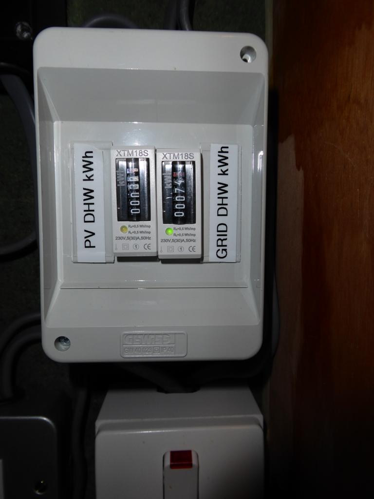
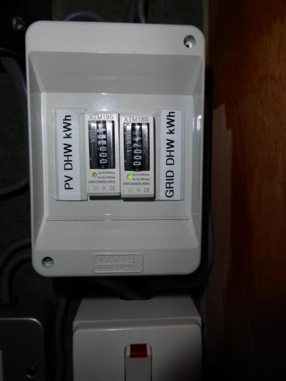
Just taken a photo of the two energy meters that I have connected to the Sunamp. One is connected to the PV diverter, so records the energy we get from excess PV generation, the other is connected to the boost time switch so records the energy used when we boost the Sunamp during times when there isn't enough excess PV generation.
-
It's shown in this post: https://forum.buildhub.org.uk/topic/7405-sunamp-not-heating-the-water/?do=findComment&comment=127385 There's also a source for the neon I used in this post: https://forum.buildhub.org.uk/topic/7405-sunamp-not-heating-the-water/?do=findComment&comment=127404 I'll take a photo of the two energy meters later today and post it.
-
I'll try and remember to take a photo of my twin energy meter set up tomorrow. The neon is just wired directly to the contactor coil and fitted into a spare cable gland on the base of the Qontroller. It's lit whenever the Qontroller is calling for power from the PV diverter/boost switch.
-
Ours used to be green, but now they are all a fetching shade of pink from all the local BMs. As @ProDave says, I gather this is just so a BCO can check without needing to climb a ladder...
-
No, they aren't paying me, or even communicating over this issue. Notwithstanding that, the time switch fix is a simple and pretty cheap way to overcome the failings in the Qontroller at the moment. I'm happy to just carry on using this as a permanent fix, as it works perfectly, with no downsides at all. I've checked that it's safe to do this, by deliberately turning the Qontroller off after it's shut off when fully charged, then turned it back on again, to simulate a time switch induced reset when the unit is fully charged. All that happens is that the Qontroller turns the main contactor on, then a few seconds later turns it off, when it senses that the heat cell is fully charged. This gives me a fair degree of confidence that the time switch reset procedure won't have any adverse impact on the unit.
-
Or fit a time switch... (still working a treat on ours, we're getting pretty close to 100% utilisation of excess PV generation now).
-
Best tactic if you have an EV or PHEV is to either buy a Zappi charge point or build one that has the same functionality. Mine works very like a Zappi, in that it only delivers charge to the car when there is an excess available. The only slight fly in the ointment is that the lowest charge rate that any J1772-compliant vehicle should accept is 6 A, so around 1.4 to 1.5 kW, and that needs to be continuous, not pulsed like the output of all water heating type PV diverters. It's not really an issue, other than the cycle time for the car recognising that power is available and booting up the charger to the correct level, which can be around 10 to 20 seconds or so. This means that in practice it's more sensible to just detect an export of over the 6 A threshold and turn the charger on at that level, then wait to see if there is still excess PV generation a few minutes later and if so step the charge rate up, then keep doing this (or stepping it down) at, say, 10 minute intervals. It probably means that some of the charge will be imported at times, but is about the best that can be done given the limitations of the J1772 protocol, which was never really designed to allow flexible rate charging on the fly.
-
We submitted our "design" EPC with our FIT application when second fix was just about completed, but nothing else was done, and it was accepted for the FIT OK. We did this in a rush to get the application in before April 2014. as the rates were due to change. The house didn't even have a name or address, and was listed as "The Plot", with our old house as being the address for all correspondence, FIT cheques etc. We had no problems at all in doing this, everything went like clockwork with SSE, even down to the DNO part of SSE emailing me documents that were needed to include in the application (the G59 approval).
-
 Good idea, I can't see a reason not to post the details for the chap we used, so here they are for future reference: Dan Watt at Ashmount Consulting Engineers Ltd 151 Barlow Moor Road, Didsbury Manchester, M20 2YA email dan.w(at)ashmount.net (replace the obvious anti-spam change)
 -
I have the contact details, as I offered to send you via PM if you wanted it on the other thread, for the chap that did our as-built SAP. I just emailed him the Stroma file plus some other documents, like a copy of the air test report, and he did the as-built and lodged the EPC for me. He's in Manchester, so just did everything via an exchange of a couple of emails. He turned it around in a couple of days, IIRC, and charged £100 plus VAT.
-
FWIW, we used recycled plastic "slates". About the same price as mid-quality Spanish slate, so not that cheap, but virtually no wastage at all, so there's a real saving of around 10% to 20% in material cost. The bigger saving is on installation cost, as they are only 20% of the weight of real slate, so are much quicker and easier to carry up on to the roof, and a bit quicker to nail down, but they do have to be pilot drilled for the nails. If they aren't pilot drilled the nails just bounce off, as they are moulded with a slight curve so they snug down tight on the "slate" below. Overall the cost was about the same as Tata Urban, as that was our original choice, and what was in our planning consent. We had to change away from the Tata Urban as the manufacturer of the integrated, flexible, solar panel system that was just bonded directly on to the steel roofing, went bust. Pity, as it was a really good looking system.
-
So would I, very much so! I have no doubt about the membrane, the real issue, and one that has taken a fair bit of R&D to solve, I believe, is the long term adhesion of any tape to it, even the very best stuff. Airtight membranes have been developed so that they have a surface coating, or sometimes a laminated layer, to increase the surface energy and better allow adhesive bonding to work in the long term. Some types of plastics are particularly poor, including polyethylenes and vinyls, and without some form of surface treatment any adhesive will fail within a year or two. If opting to use a budget VCL, bearing in mind that the VCL is a critical component with regard to the longevity of the underlying structure, then I would ensure that it is mechanically sealed at every joint. One way to do this is to wrap the edges over, tape them and then secure the joint with a batten. Fair bit of extra work, though, and given the highly critical function of the VCL I'm not sure this is an area that I'd want to save a few pounds on.
-
Sounds like a good idea, as long as you can be sure that the switches can be reached from the bed. I wasn't 100% certain exactly where the beds would end up, so we just rely on the switches built-in to the bedside lights to switch them off at night. It's easy enough to just get into the routine of switching them on in the morning when making the beds.
-
Yes, they do, so you need to change the plugs, but that's only a 5 minute job, and dead easy to change back if you ever need to.
- 22 replies
-
- 1
-

-
- electrical
- plan
- (and 1 more)
-
I'm another fan of adding 5 A sockets switched from the wall. In our bedrooms we have double gang 13 A outlets either side of each bed, plus a single gang 5 A outlet either side, switched from the wall, so that bedside lights can be turned on as you come in the door. We also have 5 A outlets in the living room for incidental lights, again switched by a wall switch. We find we rarely use the main lights in either our bedroom or the living room, instead we just switch the incidental/bedside lights on from the wall. The only thing to remember is to leave the switches on the bedside lights turned on in the morning and turn them off at the wall switch ready for the following evening.
- 22 replies
-
- 2
-

-
- electrical
- plan
- (and 1 more)
-
Might be in the South West, as the only Botus I know is Botus Fleming (went out with a girl from there around 45 years ago now...).
-
We have a 3m high retaining wall behind our house, around 35m long. We had to get an SE to design it and also needed to let BC have the SE's documents. It was expensive, came to around £30k IIRC, plus the rendering for the finish. Much of the cost was in the foundations, which were absolutely massive. The wall itself was built from 215mm wide hollow concrete blocks, laid double width for the lower half, with lots of steel reinforcing bars in the hollows, which were filled with C35 concrete. All the horizontal mortar joints also had steel reinforcement laid in them. It's mandatory to get an SE to design and sign off any retaining wall over 1.2m IIRC, or something like that. The main issue is that insurers almost certainly won't cover a wall that is 2 or 3m high unless there's an SE sign off, AFAIK.
-
SAP and EPC as built -- rock and hard place
Jeremy Harris replied to TerryE's topic in General Self Build & DIY Discussion
I used a chap in Manchester who did the whole thing via a couple of email exchanges. Charged me £100 +VAT to do the as-built and lodge the EPC, based on data I gave him (including the Stroma data file I'd produced). If you get stuck @TerryE I can PM you his contact details. -
Pointless fitting a radon sump and breathers if you live in an area where there isn't any granite under the house, as radon only forms as a breakdown product of naturally-occurring thorium and uranium, and you only find those metals in areas of the UK where granite outcrops. For example, here in the South we have 40m of blue gault directly under the house, then ~10m of running greensand, then maybe 50m or so of Purbeck limestone. There's no granite anywhere near the surface, so there is zero radon risk. Much the same applies to large swathes of the UK.
-
@oranjeboom, We have a system where in winter our ASHP heats a buffer tank to 40 deg C and water from that is then pumped (on DHW demand, with a flow switch) through a plate heat exchanger to preheat the cold water that feeds the Sunamp. This means we get a bit of heat into the water, typically it is raised to between 20 and 35 deg C before it is passed to the Sunamp, reducing the amount of energy we need to draw from the Sunamp itself. There's no problem with overcharge, as that can't happen as long as the PCM is kept below its breakdown temperature of ~125 deg C. The sensors limit the PCM temperature to well below that, no more than about 70 deg C I believe, so it's well within the allowable limit. I'd pretty sure the problem isn't a safety-critical issue, just one of dealing with a challenging sensing and control problem. I'm not convinced that the behaviour of the Qontroller has been completely and thoroughly modelled as a part of the product testing process, and that the situation of a usage pattern where less than 50% of the capacity is used before a key recharge opportunity seems to have been missed from either the specification of the test process. It so happens that our usage pattern is exactly this, so the failing, and the consequence (running out of hot water for showers) may well not have been considered during the design process (my personal view is that it was overlooked, and they concentrated on users who use more than half the capacity all the time). I know that at least one person, other than @Nickfromwales has informed them in writing of the issue, as we aren't the only ones to have discovered the problem.
-
You're right, @Barney12, it is a LONG way from being a usable all-electric solution as things stand; the Qontroller needs to be a lot more user-friendly and be able to deal with common usage scenarios without letting the Sunamp run out of charge. Our showers use pre-heated water, and run at about 10 litres/minute, so typically use around 2 kWh. One option I considered in order to force the Qontroller to accept charge after two showers was to turn off the preheat, as that would use more energy from the Sunamp and probably lower the state of charge below the ~50% charge acceptance threshold. However, whilst that might be fine in summer, in winter it would mean using more grid electricity, as pre-heat is provided from the ASHP, at around 1/3rd the cost of boosting the Sunamp from the grid. The way I have our system set up at the moment, including the modification I'm planning to add a time switch to reset the Qontroller, is this: Power to the Sunamp heating element is provided by the PV diverter (when there is excess PV generation) plus I have a time switch, in series with a boost enable switch, that bypasses the PV diverter. When the boost switch is on, the time switch supplies power to the Sunamp heater from 03:30 to 06:00 every morning, to ensure that there is enough charge in the Sunamp to supply morning showers (in theory the boost should ensure that there is at least 7.5 kWh of charge stored in the Sunamp, if it will accept it). After morning showers a second time switch, powering the always-on Qontroller supply, will turn the controller off for 1 minute and then back on again, so "resetting" it so that it is ready to accept charge whenever power becomes available via either the PV diverter or the boost timer. This means that the Sunamp "should" always be ready to accept charge after limited discharge, which "should" both maximise the utilisation of excess PV generation and ensure that it always accepts the top-up boost charge in the morning. Without "resetting" the Qontroller there is a risk that it could only have around 4.5 kWh of charge available for morning showers, barely enough to deal with all scenarios and leaving us without hot water for the rest of the day and evening, despite the unit having a nominal 9 kWh capacity. No, I'm not worried about causing damage, because I'm pretty certain that there is no way that the PCM can be damaged just by resetting the Qontroller. If it could, then the risk would be there if there was a power cut that did the same thing. I'm also pretty sure that the problem is wholly related to the way that the Qontroller tries to assess the state-of-charge of the heat cell. It seems that it can easily detect when it's fully charged, but struggles to be able to detect partially discharged states. I can understand why this may be, and suspect it's related to only being able to measure temperature at three vertical locations and then use that to try to guess how much of the PCM is solid and how much is liquid (which is effectively the state-of-charge). Resetting the controller puts it back to the cold start condition, where it uses the measured temperatures to determine whether to go into cold start mode, where it pulses the contactor on and off (to prevent local overheating of the PCM) or whether it goes into warm start mode, where it just switches the contactor on. The protection for the PCM is still there, as when it senses that the heat cell is fully charged it will still shut off OK. Good idea to split this out, IMHO. Not as far as I know. My unit is an eHW, and I believe the issue may impact any unit with the 2.8 kW electric heating element and the UniQ_SBC_01 Qontroller, but that is only my guess. It's not explicitly mentioned in the manual, or at least not very clearly. In the section for the eHW and UniQ_SBC_01 Qontroller there is reference to setting Option 1, which is defined as Option 1 ON = 90% discharge before the unit will accept any charge and Option 1 OFF = 50% discharge before the unit will accept any charge. One thing that occurred to me over the weekend is that if someone wanted to do as we did, and increase the storage capacity to deal with days without excess PV generation, then the better option would have been to buy multiple smaller units, perhaps. Might means some cunning plumbing to discharge them one at a time, but with a multi-output PV diverter such a system would then be better able to utilise all the available storage capacity. Having said that, adding a cheap time switch looks like it will do the job on a bigger unit, anyway.
-
Removing hardstanding up against a 3rd party wall
Jeremy Harris replied to Sjk's topic in General Self Build & DIY Discussion
It's interesting that the face of the wall is the boundary, as that implies that they can't have anything (eaves, fascia, gutters, vent pipes etc) overhanging your land, unless they also have some form of flying freehold in place (and I'm pretty sure that flying freeholds aren't usually used for overhanging stuff like this; the only one I dealt with was part of a bedroom that went over an alleyway that belonged to the neighbouring house, in a terrace). I agree with @joe90 about getting someone with insurance in to do the work, takes away most of the worries. -
The "switch off then on" bodge should work all year around, as the problem is that the Sunamp will not accept any charge at all, from any source, until it is around 50% discharged. In effect this means that you can never be sure that you're going to be able to keep it topped up, so in summer, when there's often lots of excess PV generation, the Sunamp just wouldn't use any of it until such time as the Qontroller thought that the heat battery was ~50% discharged. For us that means we could easily go a whole day with loads of excess PV generation without any of it being stored for use later to generate hot water.
-
Another update, this time after a week of switching the unit off after morning showers, then back on again to "reset" it. At the moment I've just been doing this manually, with the main isolator switch, as I want to see whether it's worth wiring a time switch in series with the Qontroller supply or not. Not too much excess PV generation this week, but I believe there's a difference in utilisation. In summary, this week the Sunamp Qontroller has been set to what should have been the default setting, which is to enable recharge at ~50% discharge. After ~4 kWh worth of hot water was drawn off (except for two mornings where SWMBO was away, so only around 2 kWh were drawn off) I manually switched the whole unit off, waited around 30 seconds, then switched it back on again. For 6 days out of the 7 this triggered the unit to go into charge acceptance mode; on 1 day it was already in charge acceptance mode so I didn't bother to switch it off and then on again.: Excess PV energy generated = 12 kWh Excess PV generated energy used to charge Sunamp = 11 kWh Grid energy used to charge Sunamp = 16 kWh Total DHW energy used for the week = 27 Kwh, of which 11 kWh came from excess PV generation, which isn't bad for this time of the year, in my view. I'm inclined to view this as a big improvement, as it looks as if the Sunamp is now absorbing as much excess PV generation as possible. I think the 1 kWh disparity between the excess PV generation recorded and the Sunamp PV charge may well be just cumulative error, as the PV diverter is designed to always err on the side of caution, and has a small "leak" to the grid that ensures it never accidentally imports. Over a week I can easily see that this could account for 1 kWh going to the grid rather than the Sunamp. So, in summary, it looks as if setting the Qontroller so that Option 1 is OFF, plus ensuring that the Qontroller is powered off, then on again, each morning, ensures that it will accept as much excess PV generation as possible. Unless Sunamp come up with a fix for this issue quickly, then I'm just going to install a time switch to reset the Qontroller every day, as that seems to be the only way to make the unit function as intended. It's a bit of a bodge, but at least it will allow maximum self-consumption of PV generated energy.
-
I built mine in the pre-internet era, around 1977/78, and used plans that I think were in one of the car magazines, not sure which one. They are all much the same though, and use either a pan type burner or a centre-fed disc burner. At the time I built mine the disc type was thought to be easier to clean, as they do tend to coke up a bit, especially if not run pretty hot. IIRC, the tricky bit was getting the air feed right, as the secret is to have a low temperature burn where the oil runs in, with a much higher temperature burn above that, in the main chamber. Mine was made from around 4ft of scrap 12" diameter, 1/4" wall thickness steel tube, with plates welded on top and bottom, and a bit of 4" steel pipe welded on the top as the flue, which went straight up through the wrinkly tin roof. There was a hinged door on the side to get at the burner, plus air holes drilled through the lower part of the case, which was held around 2ft off the floor on angle iron legs. Sadly I don't have any drawings of it, but I'd guess a look around the web will probably find some, as they have been around a long time.