
Nickfromwales
-
Posts
30346 -
Joined
-
Last visited
-
Days Won
297
Everything posted by Nickfromwales
-

Site security, getting robbed.
Nickfromwales replied to Russell griffiths's topic in General Self Build & DIY Discussion
My mates Vivaro got emptied the other day. 3mm hole made around the sliding door handle. Surgical precision, near zero damage, not even noticed until the penny dropped. Luckily not his whole collection in the van that time…….. -
https://wrcpartgcalculator.co.uk/Calculator.aspx I just grab figures from these types of examples. Few ‘inspectors’ ever cross examine or even check tbh. Just a box-ticking exorcise. Posts on here show typical l/per person/day. Google will point you to most common information, plus feedback from others here should fill the gaps.
-
LINK
-
90% done, only 90% left to do……
-
Just tell me that the band is temporary ;).
-
You need a minimum of 600-800mm of slack just to install the panel. When the panel is down, that slack cannot practically be anchored. Move on to the next item, this ones fine afaic.
-
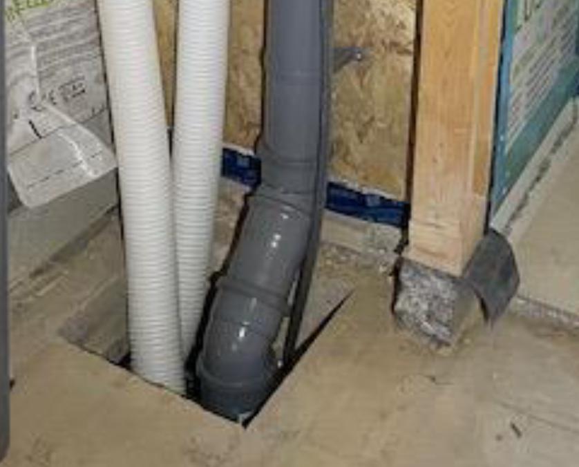
It’s fine. Much better than the previous splat and stop arrangement If this is your first crack at soil pipe runs, then you’ve just beaten the “30 years in the game” fcuk-ups laid by my current clients ( now since discharged ) builder Looks like a first year apprentice laid them. Whilst hungover, then realised what a bag of shit it all was, and then hurriedly back-filled it all without informing the BCO ( as it first needed inspecting by them!?!? ). You’re doing very well. I’d put the 2x 15’s at the wall end, so the highest velocity pushes through those, and then the flow through the 45 & 135 will be far smoother.
-
Unless you specified conduit / other, which you’d have paid for, the norm / knee-jerk is what you have. Fwiw I won’t be doing anything more on my own install.
-
The cables have a degree of ‘mechanical protection’ from being behind the panels. No harm will come to them in actuality, and they’re well insulated and further mechanically protected by the outer sheath of the cable type. As said, you need slack to install them, and likewise for downstream service / repair. Stand down red alert afaic 👍
-
I’ll get my red marker pen ready……..👀
-
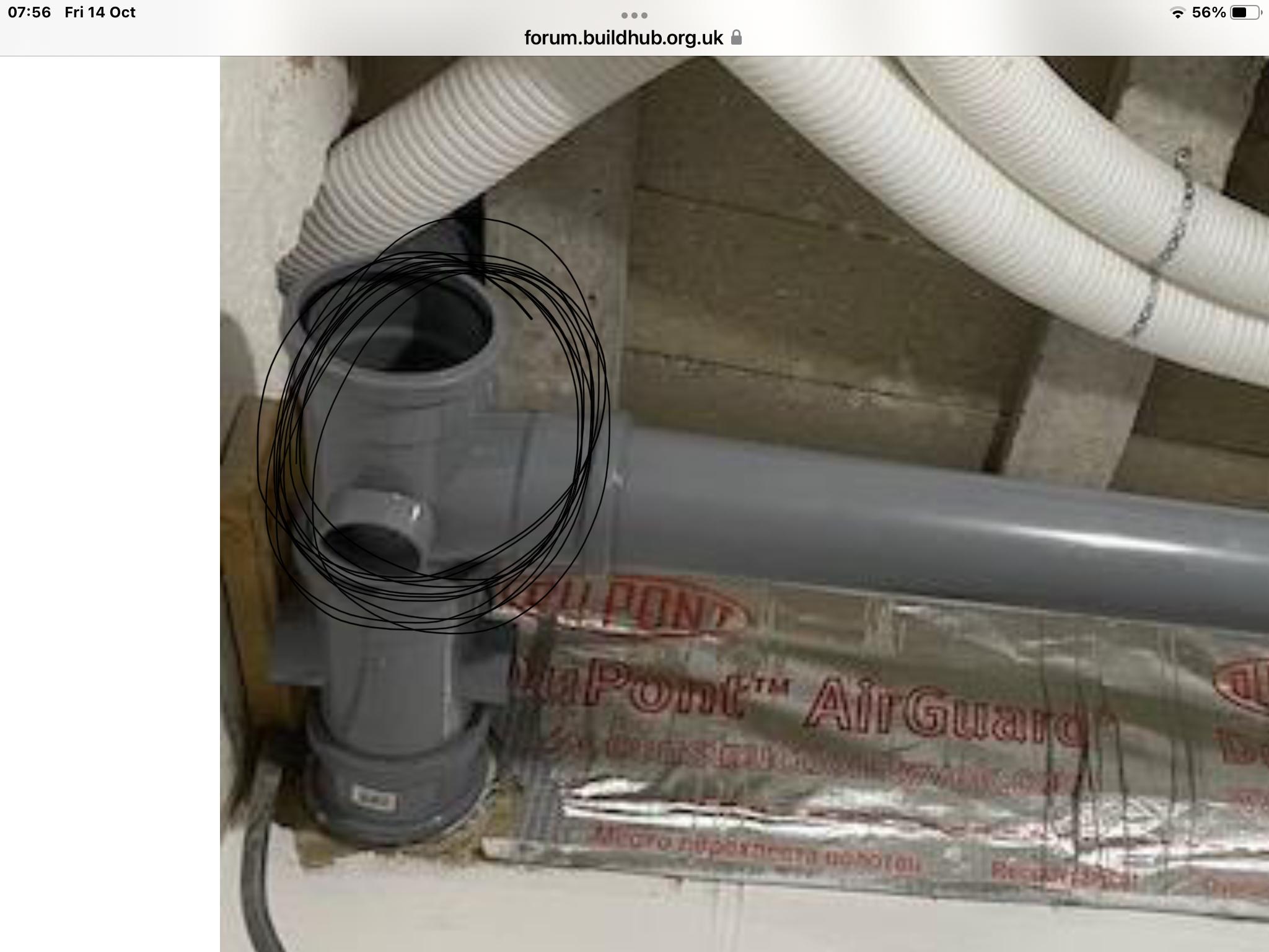
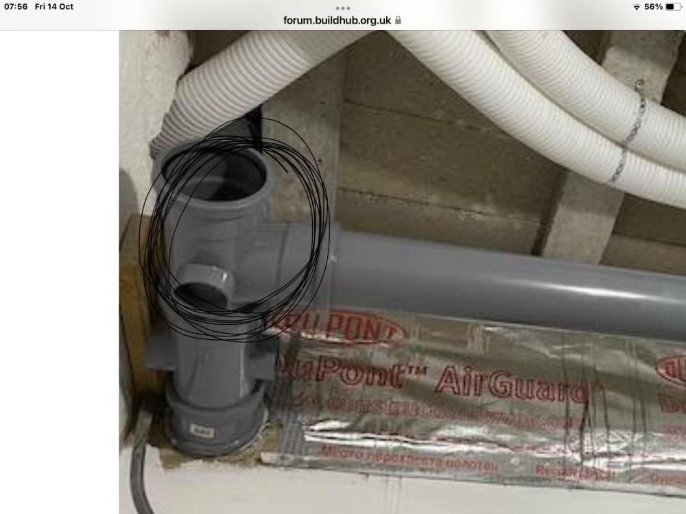
Nope. Leave well alone. The outlet of that replacement branch which would take a rodding / cleaning eye would be up against that rigid MVHR duct, so a pointless adaptation with worse results AFAIC.
-
Yup. Typically only available in the underground range. Get 2 as you’ll need to do the upstream one as well.
-
Yup. 135 is a Y branch 92.5 is a T branch. T branches are used in vertical pipework where gravity promotes direction of flow, Y branches everywhere else where velocity is the only thing keeping the brown dolphins moving as they should. Is this junction in a habitable room? If so, it’ll need a serious bit of sound deadening.
-
That one ideally needs to be the same, with a Y branch and a 45 going in to it. Edited as I was looking at the same pic twice lol. More coffee required……
-
BCO will be happy it’s not a rest bend btw, as long as you fit a clip ( rubberised clamps ) immediately on the output of the branch, and another immediately behind it where it picks up the second incoming foul.
-
People!? It matters not one jot what colour it is…… It’s never going to be the first part of the guided tour when Auntie Mabel comes to visit with the twins ffs
-
Spot on. BCO will be plenty happy with it fitted internally, just can’t be outside above ground. @Thorfun Get over the mix / match of underground fittings as you’ll be needing some. That branch, the one tight against the basement wall, needs to be a Y branch not a T branch, with a 135o single socket 45 into it to collect the bottom of the ‘drop’ from above. That’ll put the brown dolphins and they’re associated paperwork travelling in the right direction for sure . You wont be able to change to a rest bend as you’ll still need the rear open socket from the Y branch to pick up the second incoming foul pipe.
-
Spray foam insulation has to be the clear winner here? A thin layer of closed cell to detail all the gaps and seal from moisture travel, there a good 100-150mm of open cell atop that. The fabric improvements will be completely and utterly decimated by ventilation losses here though, so unless you go to forced heated air input, as well as the foam and beads, plus plugging every gap you find ( very well ) this will just be a losing battle imho. You’ll need the heated air input to keep an acceptable ACH for air quality / managing internal humidity etc, even if that’s then very small. +1 to not having any airflow, as that’s the cause of the condensation, just go tight to the corrugated panels with the closed cell foam, and lose the gaps 100%. This is a big, “thermally unfriendly” building in which to achieve what you’re looking for, so either all in or don’t bother starting afaic Pointless putting good money and effort in to not move forwards, or make it worse. The space blanket is a waste of space…….blanket. Looking at the height of the roller shutter, even a mezzanine with storage may be an option, doubling the floor space for storage, dependant on whether, as a petrol-head, you’ll be installing a lift or 2 of course? You may be able to DIY the foam, but I’d just bite the bullet and get it separated by a company set up to do this quickly and efficiently. DIY kits will probably work out expensive over this volume.
-
Issue with ufh flow rate 10 port manifold
Nickfromwales replied to Pta's topic in Underfloor Heating
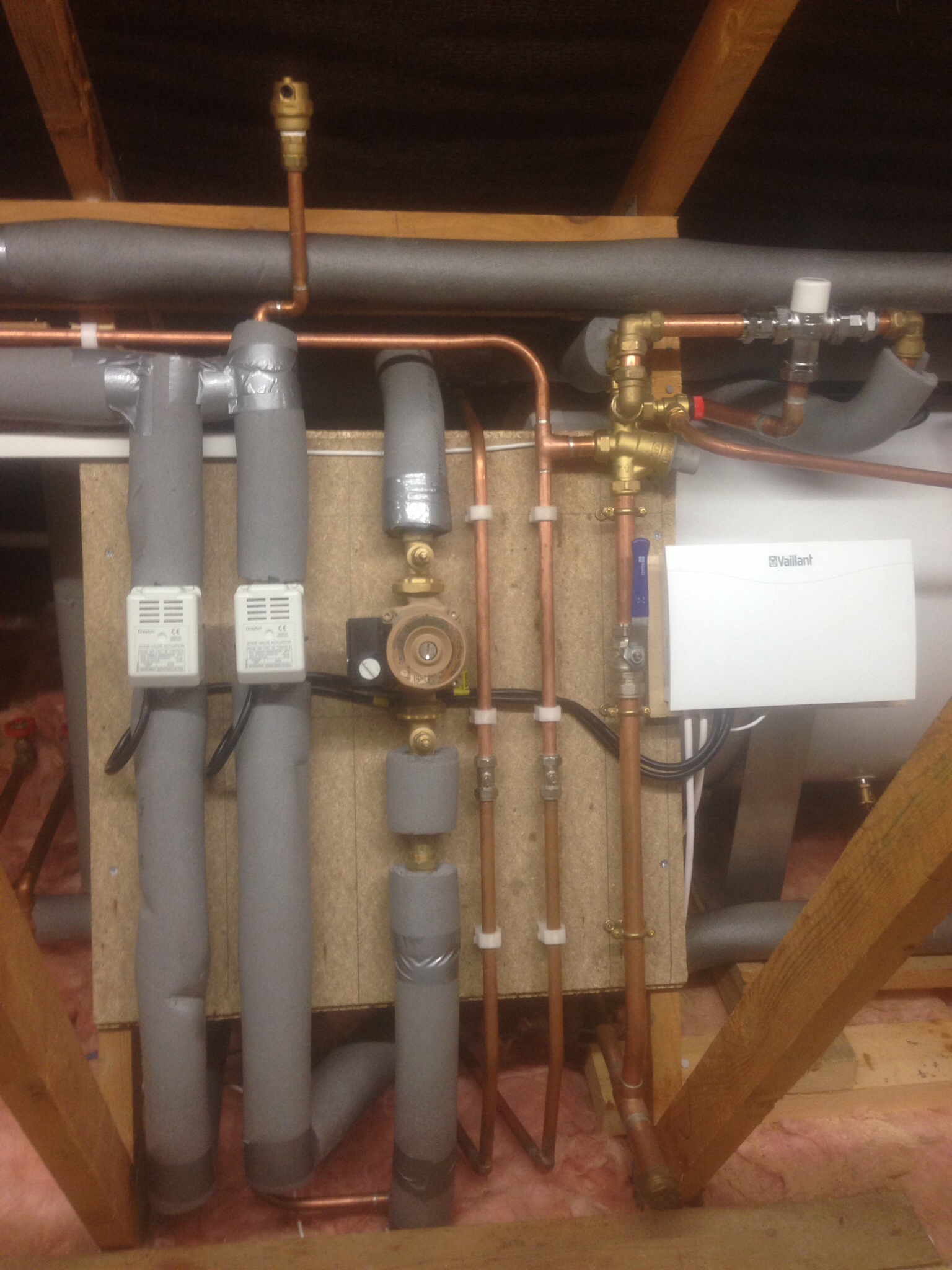
NOPE! Stop hoping for a quick fix please. The pump needs to be the right way around, the flow and return need to be plumbed to drop down and come in at the level of the lower rail, and the thermostatic valve will, ergo, be at the bottom level too. Sleep well, for tomorrow you will find a new plumber and heating happiness. There is absolutely nothing you can do the the existing arrangement by rubbing some hope ointment into it. Needs a full re-work, prob 2 days work at least for a conscientious plumber. -
Issue with ufh flow rate 10 port manifold
Nickfromwales replied to Pta's topic in Underfloor Heating
Exactamundo. If you want me to talk this through with your replacement plumber ( easily identifiable by them NOT wearing a straight-jacket ) then PM me. -
Issue with ufh flow rate 10 port manifold
Nickfromwales replied to Pta's topic in Underfloor Heating
Ah, OK. Just so you know, written posts on the internet / by folk on here, much as mine do also, can be seen a bit blunt or as if we’re having a bit of a dig. For clarity, any dig is at your installer and absolutely not at you. We will of course help you as much as we can You don’t need any replacement kit btw, just the whole lot needs to be reinstalled / reconfigured. Then you’ll be back up and running in no time. The kit here stands zero chance as it’s simply all installed arse over tit. Do you know a good plumber with some patience? Hopefully the wiring side will need little or no intervention, as long as the actuator cables will all reach the manifold locations after the shuffle. -
Issue with ufh flow rate 10 port manifold
Nickfromwales replied to Pta's topic in Underfloor Heating
Pumps upside down, so it’s a train-wreck. No way the MI’s ever said to fit it this way. Clearly been Frankenstein’d for convenience to the installer. -
Issue with ufh flow rate 10 port manifold
Nickfromwales replied to Pta's topic in Underfloor Heating
There is also absolutely ZERO way they your pump should be upside down!! This is a mess and I expect the pump / thermostatic valve orientations have been set up in confusion to make a left hand installation suit a right hand arrangement as far as plumbing / pipework is concerned. This needs a major removal and refitting. Stop tweaking, get a plumber, or the person who fitted this badly to come back and do it the right ( correct ) way. -
Issue with ufh flow rate 10 port manifold
Nickfromwales replied to Pta's topic in Underfloor Heating
OK. Can you give us a clear close up of the flow gauges please? Can you support that with some additional info; 1) are they 0 - 5 from top to bottom on the clear body of the flow indicators, and 2) who told you these work by being pushed upwards? Not seen one do that yet, and every single one I’ve done ( lots ) has been pulled downwards by flow generated in the flow manifold rail and never have I done one that pushes the flow gauge upwards. Happy to see that you’re setup is different, but I just need to ascertain.what’s going on there first. One thing is obvious, your installer decided to just put whatever they wanted wherever they felt like it. Actuators up on one, down on the other?!? Who installed all of this?? You say the flow gauges are showing zero, I say they are being forced to zero by the water pushing them to the park position. -
Ok, that’s all good if your BCO has green-lighted your green blob The base of the stack 1000% needs to be a rest bend, and the branch to collect the kitchen needs to be a Y branch set at least 600-800mm downstream between the rest bend and the chamber ( IMO ). As always, your BCO resides above everyone here as they will be signing it off…….but it sounds like your BCO is a pragmatic fellow, happy days! Some are total cocks. Understood regarding the chamber to the kitchen So; All systems go. “Carry on!”. 👍