Moonshine
-
Posts
2094 -
Joined
-
Last visited
-
Days Won
6
Everything posted by Moonshine
-

Rooms above garage - Thermal envelope?
Moonshine replied to SuperJohnG's topic in New House & Self Build Design
you are correct as below (best check the regs to make sure its still valid) -
is that two outlets per side of the ridge and 1:40 fall, and surely that can't be 2 outlets for each of the smaller sections. I have been looking at scupper drains that would not compromise the insulation, also could have the main scupper drain connected to a down pipe, and a couple of overflow scupper drains that weren't connected to down pipes, these would be emergency over flow, that would be stepped up 10-20mm so they only were in operation is the main drain was blocked. tbh i haven't looked at what i want to waterproof it with, what is typical for a flat roof?
-
Rooms above garage - Thermal envelope?
Moonshine replied to SuperJohnG's topic in New House & Self Build Design
yes the floor will need to meet building regs for fire and thermal insulation. Also the door to the mud room will likely need to be a 30min fire door with smoke seals. The bedroom has some long spans over the double garage, so you will need to think about getting the spec of the timber joists right so you don't get too much deflection / bounce. This may limit the floor to ceiling height in the garage, but not the end of the world. Careful detailing will be needed when the garage wall to the house meets the floor for thermal performance. -
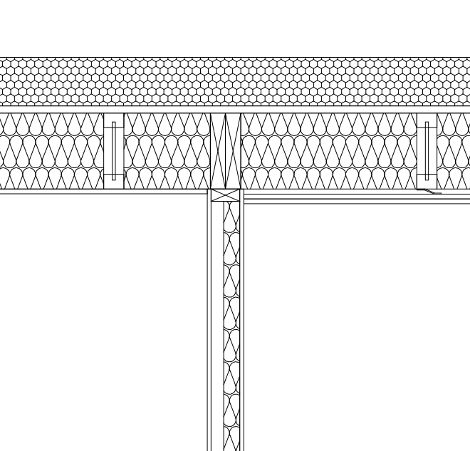
Thanks some very apt points, a few responses I don't know for sure if that area (max 23.5 m2) needs two down pipes, i am hoping to use wide box gutters to negate the need for more down pipes. Where could i get a definitive answer? yeah the planning design is for a parapet wall. The warm roof / dew point is a very good issue to raise, and i have a bit of a calc of the two as attached and i think that i will stick with 150mm PIR above the roof deck and scale down the insulation in the cavity to 100mm. the condensation risk / poor insulation under the box gutter with 100mm PIR under is my main concern and i don't know how to get round the issue, and how it is done elsewhere. would the service void go beneath the joists? 25mm? U-Value Calculator - ChangePlan flat roof with 100mm PIR board.pdf U-Value Calculator - ChangePlan flat roof with 150mm PIR board.pdf
-
Thanks, that is very nice solution, though i can't see how the insulation sites around that gutter former. @Barney12 can you advise? plus my design has a parapet wall
-
A New Wall Appeared from Santa
Moonshine replied to Ferdinand's topic in General Self Build & DIY Discussion
That's an interesting side deal, being nosy can you give details how that works? -
Interpreting deflection numbers in a 1st floor joist design.
Moonshine replied to epsilonGreedy's topic in Floor Structures
Did you go for the 8mm deflection criteria? -
On looking at that, the profile seems to suggest it needed to go under the battens and more of a product to be fitted when built rather than retrofit
-
Thanks, I have just found the below product, which looks as though it fits the bill as a elongated C on a batten https://www.pvcbuildingproducts.co.uk/manthorpe-linear-dry-verge-unit---left-hand---grey-3730-p.html?gclid=Cj0KCQiA7aPyBRChARIsAJfWCgK-sHEP68C7c49V0zW8xcWUA4XjI-D2QTU_sg0vvwRATWPX58gB6QgaAiIjEALw_wcB
-
Interpreting deflection numbers in a 1st floor joist design.
Moonshine replied to epsilonGreedy's topic in Floor Structures
Yes, and those were the loadings in your first post -
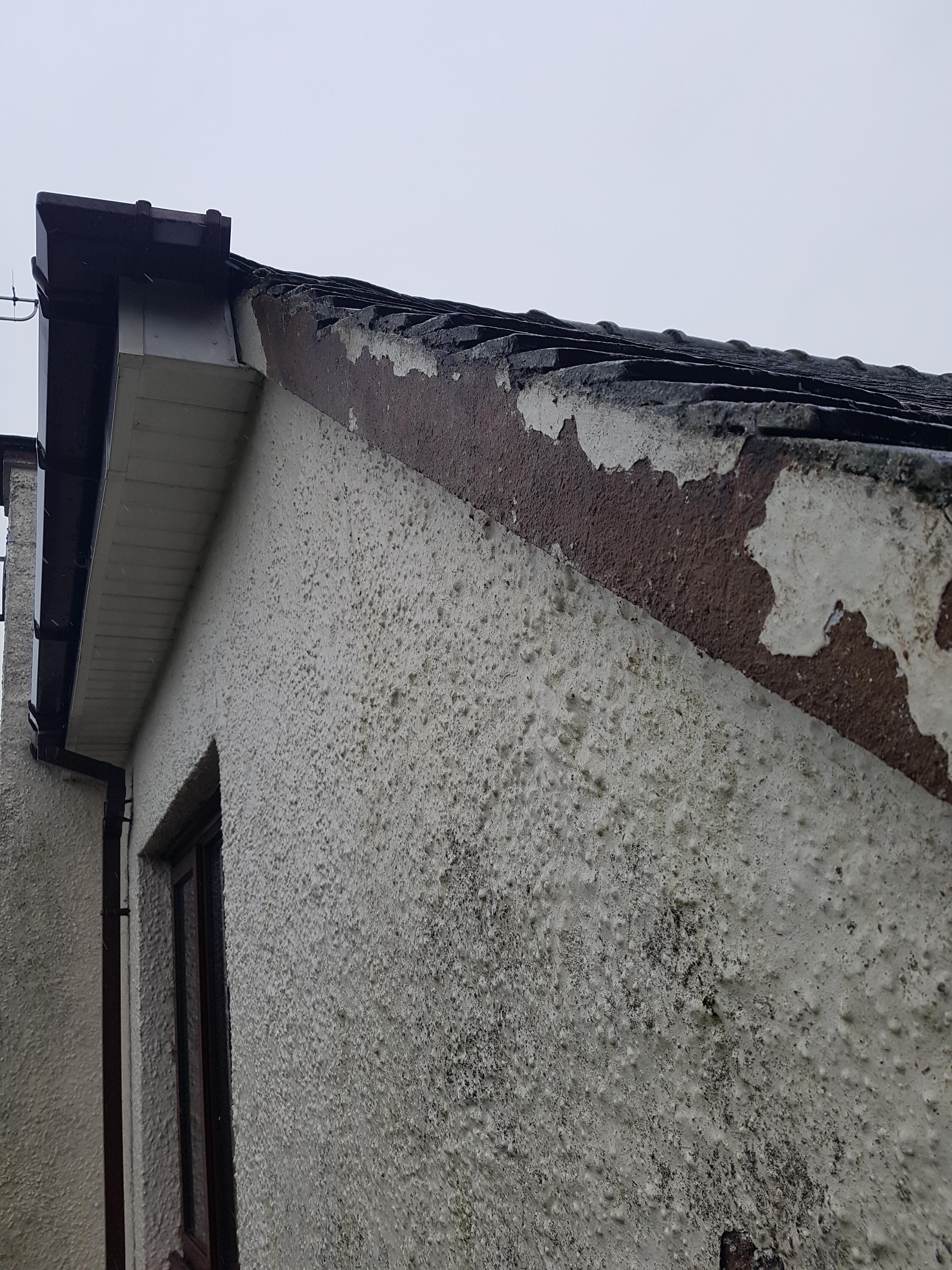
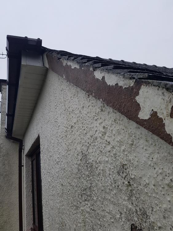
On one of the most exposed walls of my house I am getting water ingress, that looks to start at the top, gets behind the render / paint at the top where it meets the tiles, then and into the wall The attached image is the verge, which I have taken the paint / render off, which was flaking at the top where it met the tiles acting like a rain funnel. Also of this was easy to get to off as it was coming away anyway The design of the verge isn't great as the tiles don't fly over the wall edge. Most dry verge systems I have seen are based on the tiles flying over the wall by some margin Simply this could be a upside down 'L' profile shape that overlaps the tiles by a good margin. Other thing I could drop box a put a batten down the existing masonry section that the dry verge would fit to, this could be a kind of 'C' profile with a longer top to overlap the tiles. Thoughts?
-
Interpreting deflection numbers in a 1st floor joist design.
Moonshine replied to epsilonGreedy's topic in Floor Structures
umm i don't think those are deflection criteria, they look like the loading. From my limited knowledge what i understand is that deflection limit should be 0.003 times the span, with a maximum deflection of 14mm (with strutting), 12mm (without strutting). http://www.newbuildinspections.com/wp-content/uploads/2016/06/LABC-Warranty-Technical-Manual-V8.1.pdf page 32 So for that max span of you are into the 14mm/12mm maximum. There is an interactive span calculator for MiTek metal web joists which may be useful to you, as it calculates deflection for different joist constructions https://www.mitek.co.uk/span-calculator/ For 5500mm the PS-10 posi at a 253mm depth @ 400 C's (97mm width) its calculating a 12.52mm deflection. -
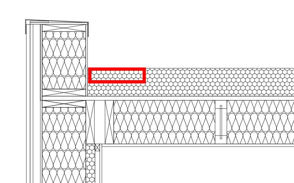
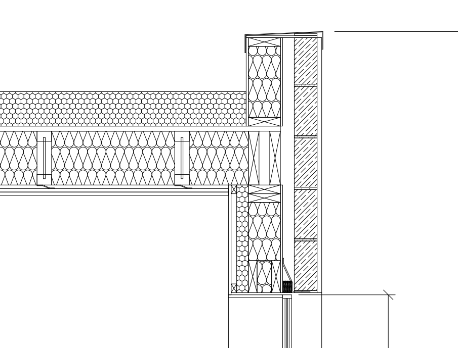
i am looking to construct a flat warm roof and now my attention has focused to how to get water off the roof(s) to down pipes. Attached is WIP roof plan, showing 1:40 falls, going to 300mm wide (is this enough?) box gutters that drain to down pipes. Also attached is the work in progress section E-E, which shows the roof make up but is going to be edited, as its currently 150mm PIR, but will go down to 100mm, and needs furrings shown for the 1:40 fall (where do the furrings go? above joists and below roof deck board?) I need to put the box gutter in, but not to sure how to detail this, and how deep do they need to be? Is it acceptable to have an area with thinner amount of PIR under, as below? 204_-_roof_plan.pdf 209_-_Section_E-E.pdf
-
Storage Mezzanine - Dead and Imposed loads?
Moonshine replied to Visti's topic in General Structural Issues
No it's not, K is multiply by 1000, but to convert N to kg you need to divide by 9.81, earth's acc due to gravity -
No biggie, at the head of the wall just fill the gaps between the joists full with porous insulation, and use the same plasterboard arrangement for the ceilings as you did for the walls.
-
If the separating wall between the two goes up to roof level / joist, then it will be o.k. as below, However if the wall runs perpendicular to the direction of the joists then you will have potential flanking over the top of the wall. Do you know what arrangement you have?
-
to reduce it from the rooms above? or due to flanking noise via ceiling void from the room to the side?
-
so its the sound insulation of walls you want? O.k, min 50mm fluffy stuff (porous insulation) in the cavity, and 2 layers of 15mm dense board (min 12 kg/m2) either side, and if you want more, mount this board on resilient bars. If you want event more acoustic performance, ditch the single stud and use a staggered stud
-
is this noise from the outside breaking in, or noise from rooms above? look below as some of the different densities of plasterboard. If its external in, this is what i am doing for reduce noise in bedrooms from aircraft noise 100-150mm PIR 22mm roof board 200-250mm I-Joists min 200mm porous insulation within the cavity. 2 x 15mm Soundbloc (or similar) of resilient bars
-
2020 Budget - Stamp Duty...
Moonshine replied to Mulberry View's topic in General Self Build & DIY Discussion
Its an interesting idea, and one personally i don't like, but if it changes to a level 25% then probably one that i could stomach as if it encourages more people on lower incomes to contribute to their pensions. Now if only the government would look at the high income child benefit tax charge criteria! -
Very similar to an assessment of an external A/C condenser unit.
-
Picture?
-
£1500 pee M2 turn key is keen, hope you get that. what is the spec/construction?
-
Foundation cold bridging - aircrete blocks
Moonshine replied to Moonshine's topic in Heat Insulation
Do you know the manufacture / spec of the blocks? -
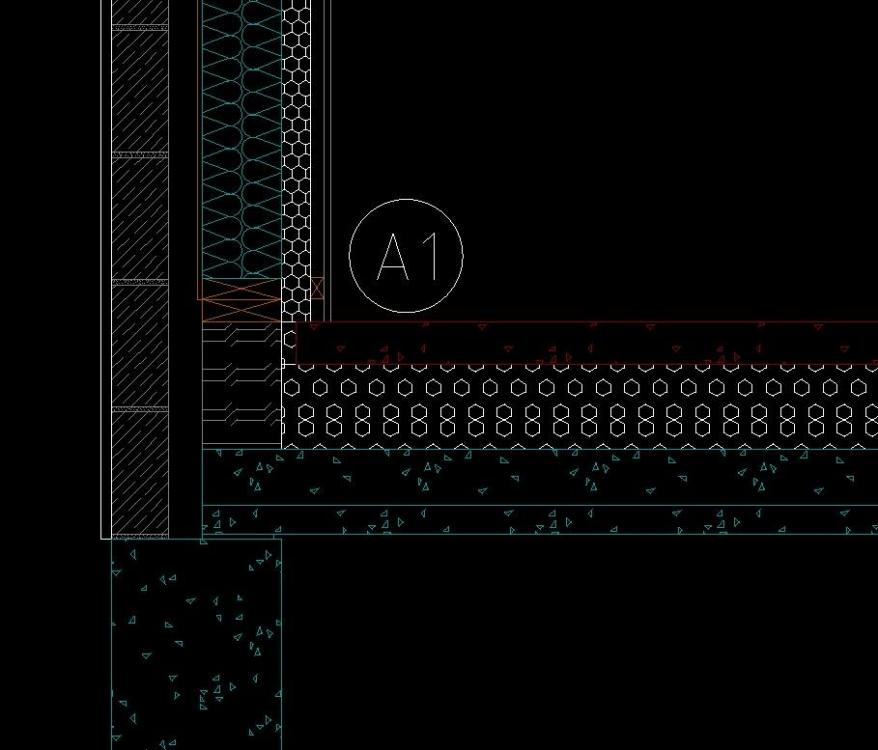
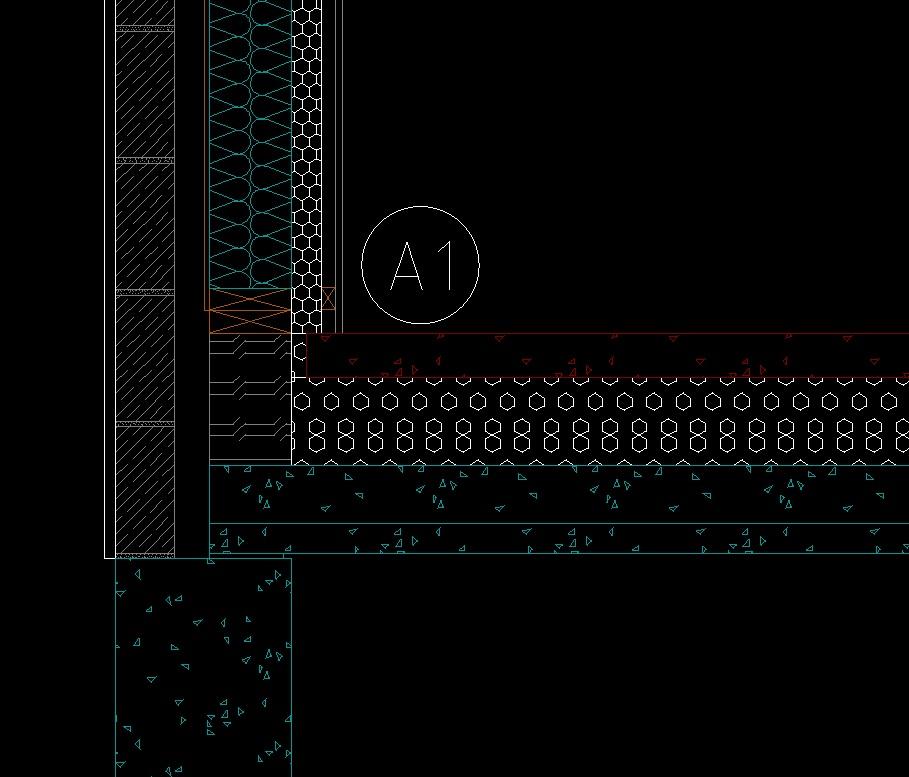
I am looking to minimise the cold bridging from foundations to an internal wall (timber), and have read that aircrete blocks can be used rather than using a propitiatory product (e.g. thermoblock), this is the detail with a 140mm aircrete block supporting timber frame, i presume these will have to be circa 7N. The note A1 reads Is there a better way of doing this detail, and would using a product like thermoblock be significantly better?