Carrerahill
-
Posts
2132 -
Joined
-
Last visited
-
Days Won
10
Everything posted by Carrerahill
-
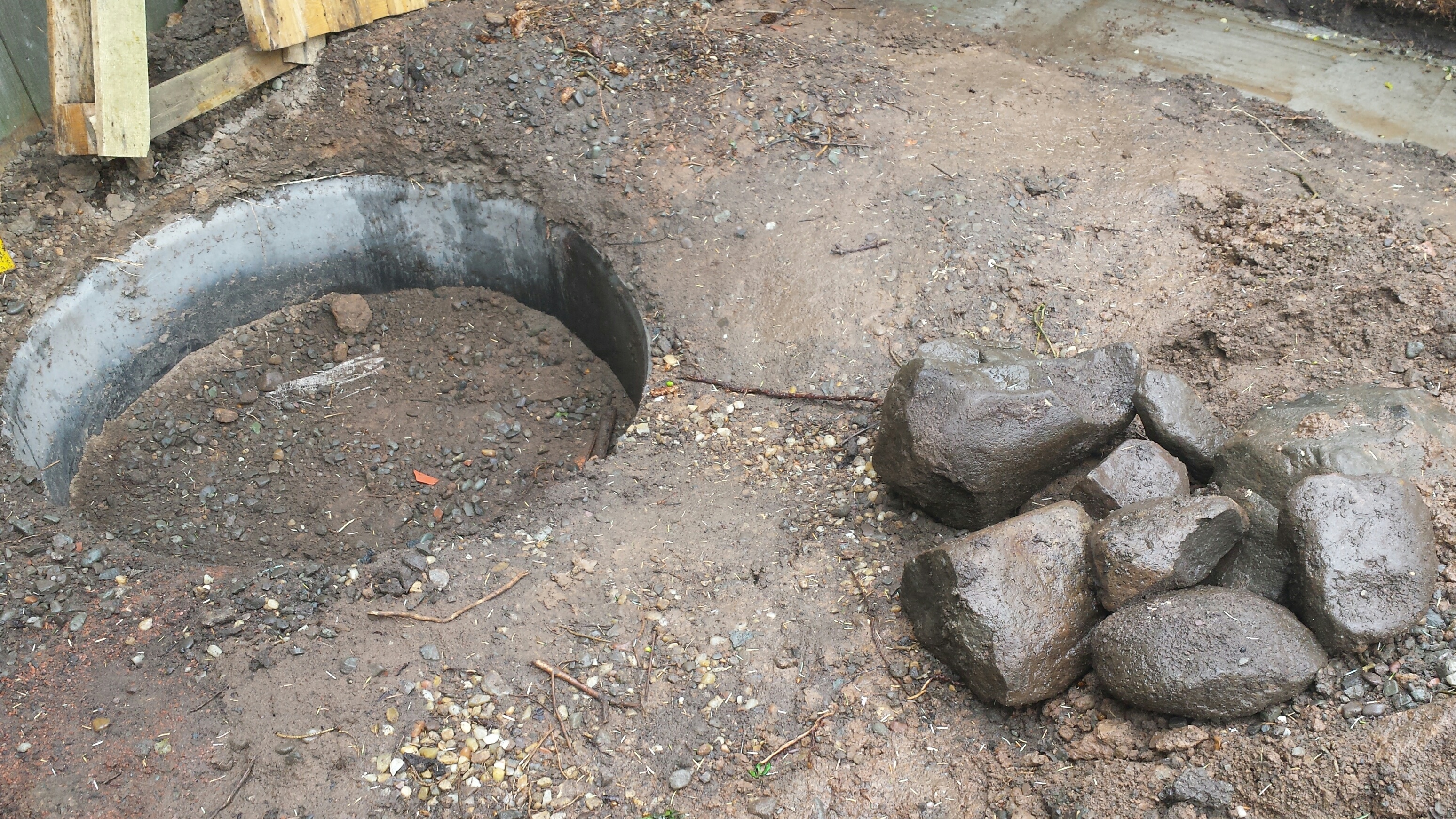
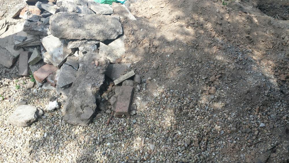
The thought had crossed my mind! There is no pipe running into it and I cannot work out what it would be soaking away being where it is, unless it is the remnants of one. Our house is built on the highest point of a hill so I don't see someone trying to improve drainage as such, and the house is old enough the gutters would be connected to the main sewer. If it was a home made soakaway then it's a poor attempt. I will probably use it for the garage roof gutter catchment/soakaway system I am going to build.
-
How to build a rainwater tank system from IBCs?
Carrerahill replied to Bitpipe's topic in Rainwater, Guttering & SuDS
Where in the country are you? I may be able to help with IBC's. -
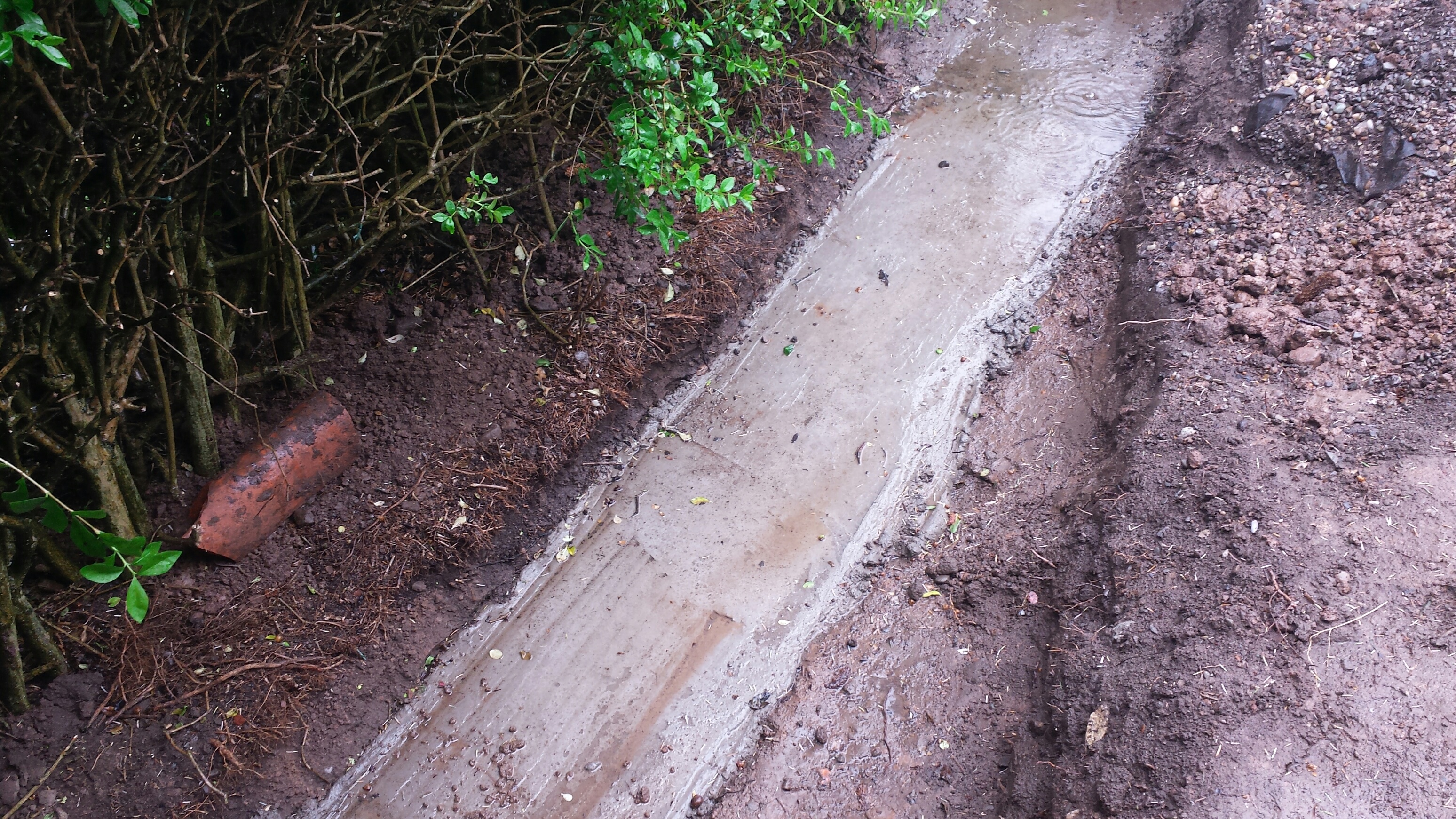
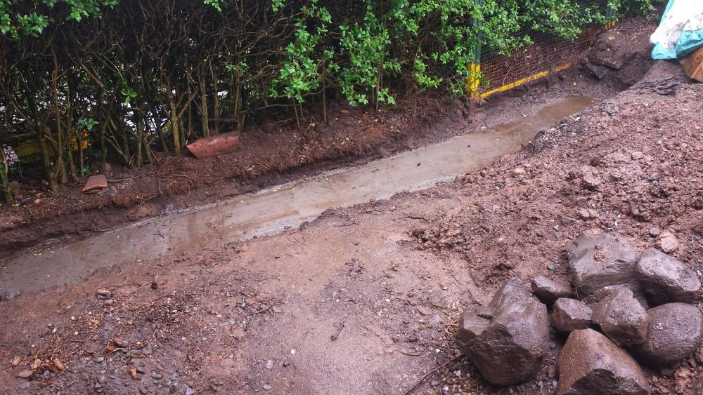
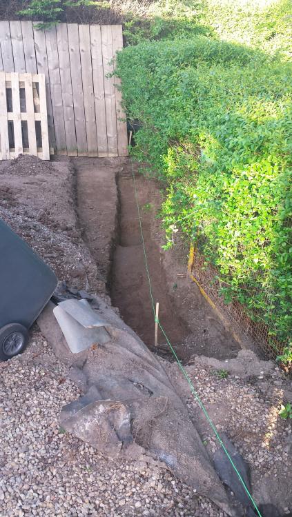
Update: Saturday it was pouring, first rain in 6 weeks, typical! It dried up in the afternoon and I went back to the trenches, got my levelling pegs in and scraped one end down a little to make sure I got a minimum of 150mm - but probably more like 175/200! I went to Trade Point and got 6 bags of cement (already had 4) and some sharp sand and all in 1 - I have loads of aggregate already and the 'quarry' remember! So Sunday I fired up the mixer and went for it. I was using a whole bag of cement which is more than '1' in the standard C25 ratio so should be well over a C25, slump was good too, I could tip a bucket and it kept it's shape well - I was happy. I ended up doing about 8-10 mixer loads, just kept going to get a good pour. I exhausted my 'quarry', and was left with some sharp sand and 2 bags of OPC so that's a bonus. I am still not sure what the 'quarry' was all about, once fully excavated it appears to be a piece of plastic storm drain pipe about 400mm deep, 1200mm dia that was sat into the subsoil then filled with sand and aggregate. I wonder if it was a way for the them to contain their materials at the time, then it was membraned over and the whole area covered in river pebbles... Anyway, it's all been used in the concrete and also means when I come to scrape that site I have an area to dump some of the spoil to make it back up to a reasonable height. I am tempted to take the pipe section out and use it elsewhere in the garden for a soakaway catchment area if I fill it with gravel and cover over.


-
You are thinking more of a resistor which will dissipate energy as heat - yes wasteful. This is also a common 'fix' that was used for dimming LED's but was not ideal as you now have a resistor somewhere getting hot! Anyway, capacitors are connected across the L and N of just about every electronic device or device with a motor. Usually they serve to suppress spikes helping to smooth the power, but can also actually improve the power factor which reduces consumption. Large factories sometimes have a bank of huge capacitors connected across their main incoming supply phases to improve power factor which means machines run more efficiently and therefore reduce consumption - it can make massive savings. So in this circumstance the capacitor sits between line and neutral, the induced voltage is absorbed by the cap, then when the current alternates it empties the previously charged side, so all the cap is doing is really temporarily storing the energy. There is some inefficiency but it is tiny.
-
You could dissolve it. Reduce it to a little bit of goo, bag it up and bin it. There is stuff you can buy to do it, but it's just a solvent (cough Petrol cough), acetone works too. Building waste is a massive issue and one that on commercial projects annoys me when you see 10-15 sheets of brand new Celotex in the skip!
-
This phenomenon can be caused by quite a few issues, it can be if your lighting cable sits near other live cables there can be induced voltage on the line. If two way switched the runs become significantly longer as power goes from switch to switch and back again etc. so more chance of induction. Another cause can be if the earth and neutral is combined or separate at the cable head, for example, if combined small earth leakages can then give the neutral a potential voltage which can then in turn back-feed circuits. Other things can include digital dimmers, which now even includes some rotary dimmers which have microprocessors in them which use the closed circuit through the load to power itself. A capacitor on the lighting circuit can often solve this, usually simply connected in at the back of the switch - easy to get from lighting suppliers and wholesalers but a good quality 400V capacitor with sleeve on the legs would do just fine.
-
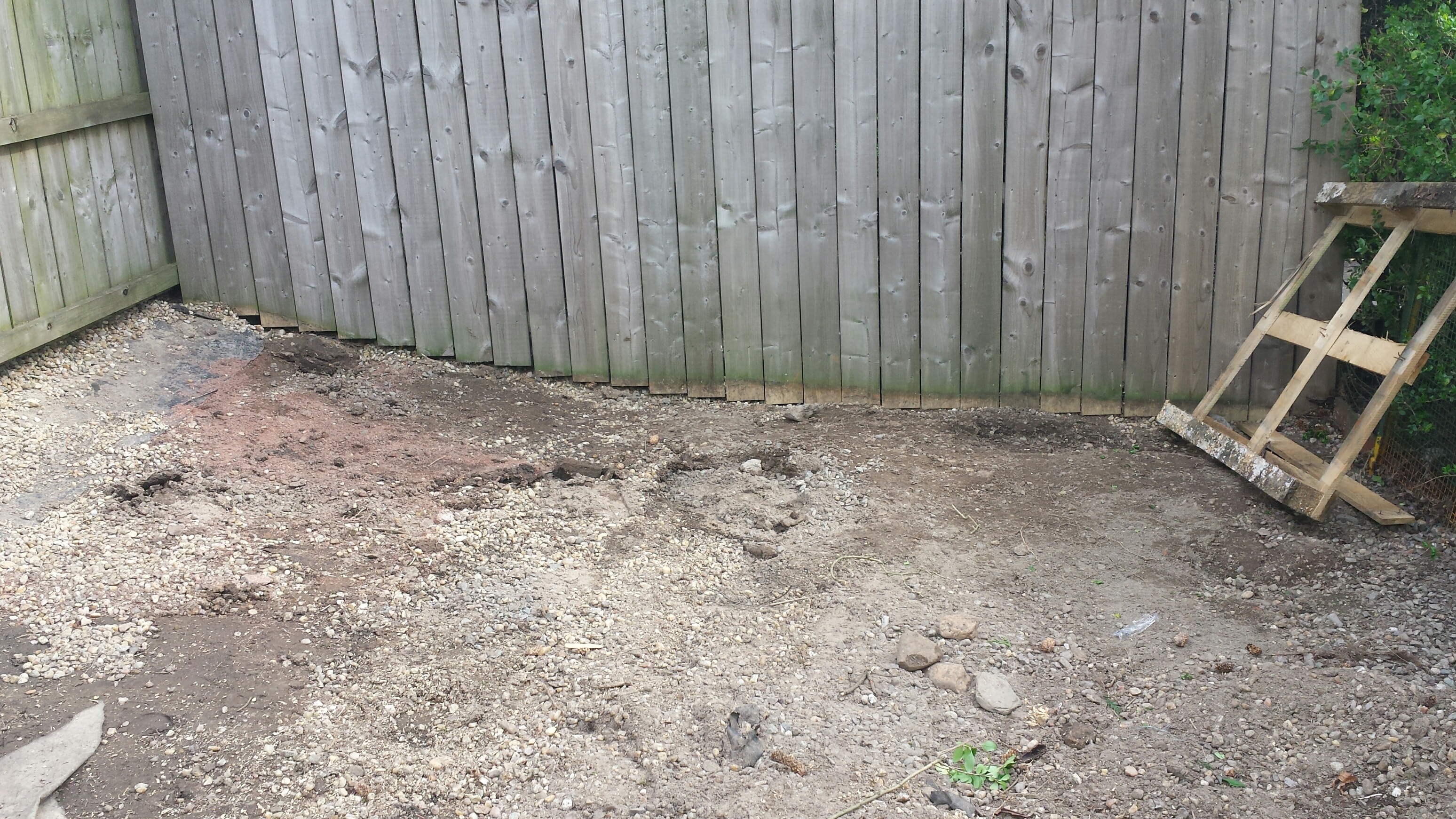
Had a little dig about at lunch there and found my own quarry! Looks like the previous owners builders or maybe landscapers have dumped a big builders bucket full of sand and aggregate, I carefully dug around the perimeter then started to extract it into the barrow. That will just do nicely for my concrete! I will dig the rest out tomorrow. Also, see image of the spoil from the excavations (picture doesn't do the heap justice, that is a good 900-1000mm high and 2400mm x 1800mm heap) just to give you an idea of what I have heaps of and will generate more! Just to show what I am planning on using as back fill to raise the lawn. Also, looking at it I am going to have HEAPS of peagravel and river pebbles, even if I top up some areas and keep a load for filling down the side of new paths and whatnot could I use some as the first fill before hardcore for the garage slab? I am not trying to be cheap here as such, I am trying to be smart. I just see a lot of potential from a lot of good material that I have gone to the effort of keeping separated during my digging and don't see the point in skipping it all to pay for other material to come back.

-
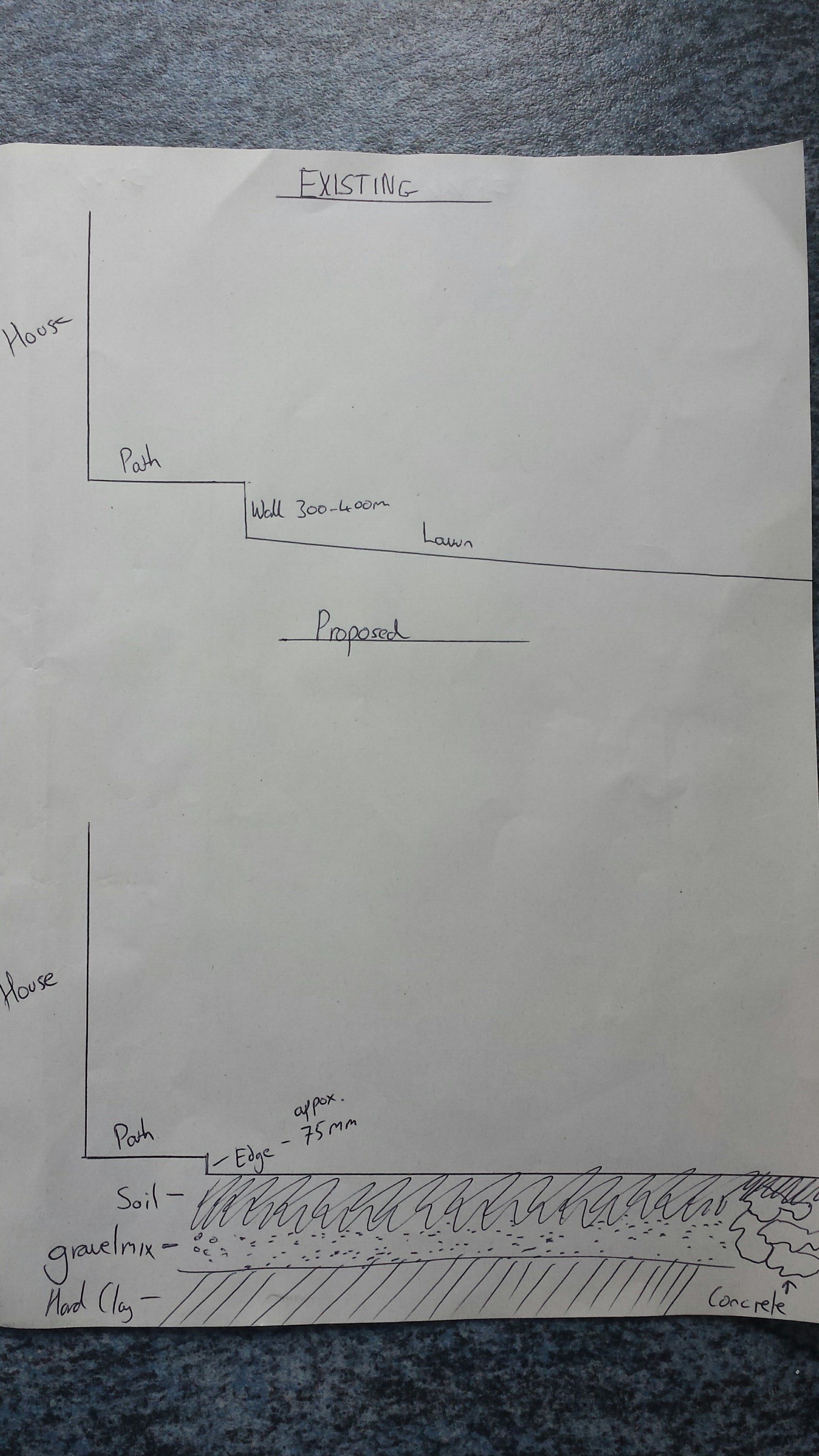
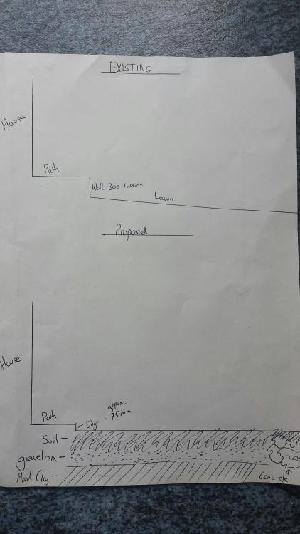
I have yes, not too bad really, with the glorious weather it has made for quite a few very sweaty grubby days. The ground is gravel on membrane, then gravelly soil and a lot of pea gravel and old building supplies from a previous extension, so lots of sand and hardcore and stuff, that is the hard bit, then it's top quality soil for about 300mm which I shovelled into buckets and dumped in a pile on my lawn which was hard going - I have a barrow now! Then it's hard hard clay which takes a lot of breaking up and once broken becomes a nice sandy consistency so does shovel well. I have now squared that trench off and checked all my lines (I will recheck again on Saturday before the concrete goes in). I will then get a block wall built up to ground level. So what do you think of this plan: Use the excavator is to dig up a fair chunk of the old lawn down to the hard clay, probably down at the lower end (which I want to raise about 300-400mm) I expect this will be a 300-400mm dig of soil, then dump all the gravelly stuff already removed from the garage site directly onto the clay, then scrape the whole garage site of the gravel and gravel containing soil and the clay sand from the trench and dump it in the lawn, I am also going to remove a section of the car parking area from the front garden which is a mix of hard core, sand and river pebbles, I will save as many river pebbles as I can to top up areas where I will retain these, once all of the sites are down to soil I can then level out all the gravelly mixed stuff out on the lawn site and compact it. Then I will go back to the garage site and scrape the required amount of topsoil off to allow for the hardcore/concrete, then I will re-level the lawn with the original soil, compact it then top it all off with the good soil from the garage site etc. Generally does this sound like an acceptable method and best use of what I have to achieve what I need, I expect the lawn will have 300-400mm of soil over the gravelly stuff so I do expect it will work well, I will for sure use pre-turf soil before the lawn goes down. This then gives me a level to work with. If it is way short I will then need to think about removing the patio and lowering it, again spreading the scrapings around to get a new general height, if it is only off by say 100mm I will just bite the bullet and buy in more top soil. At that I can lay my new lawn and install a lawn to the small section at the front, the car can temporarily park on the scraped garage site. Then it's hardcore time, shutter the site up (using the block wall for the rear shutter) and hope to get a pour in for the end of May - lets hope planning is in by then as I won't pour concrete until the garage location has been approved. I did have a thought about the concrete from the old drive, when I dig down to the clay on the lawn site, do you think I could put the concrete down on top of the clay, this will help to elevate this area quite quickly, I would even make it proud of the current level, so by the time a 300mm cover of soil is over it it will help to create the little slope I will need so the lawn can drop back down to the original level. See sketch.
-
Well those of you who read my introduction may well know that I am planning on building a new garage and converting a sun room into a proper room for a new kitchen. Anyway, I have started the garage, although I still have no planning permission I have started the ground works, even if there are changes in the proposed garage much of what I have done so far still needs to be done - even if we were outright denied planning I would still pave this area for parking - hence works not a waste. I have not fully exposed the site to keep the garden secure for now but I have cut in most of the shear key for the concrete and then dug the trench for the rear found - it needs squared off etc. but that was the first dig to get it all into rough shape. I will have a 1.5ton excavator soon so I can scrape the rest of the site, I am also building up the lawn/dropping the patio as part of these works so the current lawn will be dug up, then a deeper hole or trench dug that the gravel from the garage site can be dropped into a good few feet down (if it was cleaner I would have used it for the first layer before hardcore for the concrete - I guess I still could), then working carefully I will then scrape the good topsoil off and that can go into the lawn. Then I will lift a big patio, scrape the sand and whatever else is down there off, if good sand I will work that into the soil for the lawn, then basically pull the whole patio area down into the current lawn, I will then basically accept whatever level that leaves me with, but it will be the same level throughout with a very slight incline to the garage. I will keep this posted as stuff happens. This will be a true build thread and it will be slow as I am doing it after work and weekends as well as other projects and interests.

-
I use an airline, close your eyes first!
-
Yeah, best piece of advise when using resin, clean out the hole. I have seen these fail because muppets drill a hole and then just back fill with resin, it sets up a treat in the powder which is like a release agent!
-
Oddly our extension calls for almost an identical connection to the existing house - our building warrant drawings show M10 stainless threaded rod at 600mm centres using: http://www.rawlplug.co.uk/products/bonded-anchors/injection-cartridges-systems/polyester-resins/r-kf2/ I would check with your architect or engineer or inspector though.
-
Yes, they will all just have terminals for in and out - see edit in post above - I added a link. Normally I would suggest if you are not sure to seek pro help, but to be honest it's a very simple 2 wires one side, 2 wires the other side connection.
-
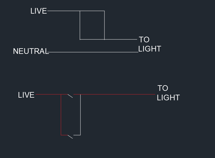
The emergency lighting is fine, we can essentially ignore it, it will have a live feed direct from the lighting circuit which is its permanent live to charge the batteries, there should be a little charge indicator LED. Just out of a matter of interest why do you have EM lighting in your home? It is very rare to see it in a domestic situation. So, you have a parallel switched circuit then. So look at my original reply regarding how it works and look at the attached image, basically if you imagine a piece of wire sitting horizontally in front of you, this is the live. Then imagine sitting below it horizontally another piece of wire, this is the connection to the light. Now if you want to switch it on you need to continue the circuit between the two, so you get another piece of wire and lay it across the two horizontal wires to bridge them - the power can flow from top wire to bottom wire and the circuit it closed. Now take another piece of wire and drop it across the two horizontal wires, nothing will happen, it just means there are two paths for electrons to flow. Now if you lift the first piece of bridge wire you put down the light will remain on unless someone lifts the second piece - your pneumatic switches work exactly the same way. The reason you have 2 wires at each terminal of the the switch is because that is the wire going on to the second switch to create your long horizontal wire in our explanation above. Look at the bottom diagram and you will see the red lives comes along, but another red live goes to the bottom switch. The white is the black in your case which goes back to the other side of the first switch it is paired up with a red which goes to the lights. Any pneumatic switch will work: http://www.screwfix.com/p/elkay-columbus-pneumatic-time-delay-switch/68088?kpid=68088&gclid=CM_gmKrnxNMCFQ0R0wodVGIE6A&gclsrc=aw.ds&dclid=CPTdp6rnxNMCFawB0wodjgYC-w
-
He does say he has a switch at the base and a switch at the top which made me write what I wrote - lets see what he says - if he forgot to mention a 3rd location then we can go back to the drawing board. However, if it was an int. switch circuit then the pneumatic switch wouldn't work the circuit properly because the wires have been combined so all three switches would need to be on for light. If it was in a combination with a 2 way switch it would also not work as the pneumatic switch would need to be on for anything to happen and regardless of switch position the lights would be on as the 2 way switch wires are combined.
-
Hang on, hold fire. I don't think this is as simple as replace with a normal switch. That is still known as a single gang switch, gangs in switches and sockets is how many independent circuits/sockets it has. I could do with a sketch here to show it but the circuit you have is a parallel switch arrangement. Typically used in corridors and stairs where pneumatic switches like the ones you had were fitted or now sensors. It is almost certainly not a two way switching arrangement. The way it works is that each switch simply closes the circuit at one end, light comes on, if you then hit the switch upstairs it closes it there too and the light comes on. When the switch(s) release there is open circuit in both areas and your light goes off. If you were to put a normal switch here you would loose the ability to switch off from upstairs, once the switch at the bottom is on, regardless of what the other switch does it would be on - you would need to go back downstairs and switch it off. Very difficult to know looking at 1 picture with 4 wires - but one of the red wires into Com will be the live feed, the second red wire in Com will run to the second switch. On the other terminal you have red and black wire, one of them, probably the black will be the return from the other switch so would I be right in saying it only has a red and black wire going into it? The red in with the black will then go to the light. It looks like there is a neutral connection in the back box, that will be the feed direct to the light. This means you probably only have 2 wires between the switches... so 2-way switching arrangements will not be possible. However, just in case: If live and neutral exist in the same box and run out then you will need 3 wires between the switches. If however, live starts at one end and goes to a switched output at the opposite and neutral is at the rose then you MIGHT get away with 2 wires between the switches but from what I can spy I think not. Best best, another pneumatic switch or a PIR face-plate assuming you do have a neutral.
-
Courier reqd for Kitchen Sink - Urgent!
Carrerahill replied to Fallingditch's topic in Kitchen Units & Worktops
No worries, I will help with all I can on this forum as much as I can as I am sure going to have a fair number of questions for you guys! UPS are pretty good. I would rate them amongst the best of the bunch. -
Courier reqd for Kitchen Sink - Urgent!
Carrerahill replied to Fallingditch's topic in Kitchen Units & Worktops
No they will offer up to a grand, just type the value into the box then it will ask if you want extra cover, will cost a bit more but if you want it for peace of mind then it is worth it. -
Courier reqd for Kitchen Sink - Urgent!
Carrerahill replied to Fallingditch's topic in Kitchen Units & Worktops
Get yourself over to Interparcel, basically a broker: https://uk.interparcel.com/ I have business accounts with TNT and UPS but actually find these guys to be cheaper. I probably use these guys on average of once a week - never had an issue yet and you can deal directly with the courier you then choose to book with. Just get the sink well boxed up and send away - if sinks are on some list then say it is ceramic components. I don't know the dims and weight but I just got a price as an idea for a 25Kg package 500 x 500 x 500 from one end of the country to the other and it was about £12 with tax. These guys are brilliant for eBay sales. I send gearboxes and differentials and all sorts with them - heavy heavy objects. -
That would annoy me as I want the old garage to store stuff in until the new one is built, if it doesn't fall down beforehand!
-
To be honest for the cost of a staircase you would end up making a lot more work for yourself and probably end up costing more unless you have a free supply of angle. By the time you work out all the geometry and start drilling for angles to be mounted and all sorts you will wish you had just bought a staircase.
-
Ah right OK, so you would take the skin down to the floor. I guess if the top of a block was AFFL then I could take it down to the next and then build it back up with bricks and mortar etc, then just sit the wall plate on the floor/top of the block work. That would give me a 100mm cavity mind you - that is 50mm more than the BW drawings. So I would still be tempted to overlap it about 40mm into the inside of the cavity so with the ply on it would be 49 leaving the as prescribed 50mm clear cavity and I don't loose the full 50mm in my room.
-
Wise words and I know what you are saying but I won't demolish the current garage until the new one is up anyway, I was just wanting to know if I need to tell building control.
-
Our planning application is in for our new extension and new garage, I know I don't need planning for my existing garage demolition but do I need a building warrant. My thinking is no. Thoughts? Thanks.
-
Of course, building control down south. No the warrant drawings do no show a detail for the connection of the new build to the existing sadly, to be honest it looks like a fairly standard plan he uses, my extension is shown in the middle with standard details written for all the different services and construction. If they approve what is shown, and it comes to the bit I will just need to demo the inner skin and build the timber frame up from the deck. I have also asked this question of my architect so I will see what he says. I will be pretty annoyed if demo has to take place as I told him I wanted to build up from what was existing. I wish I had just submitted a notice now and then let the inspector advise as to what he/she wants to see. It would be a shame thought as it would mean lifting the floor, lifting the chipboard, removing the insulation and removing all the joists take the wall down to the slab then starting again in timber.