


IanR
-
Posts
1842 -
Joined
-
Days Won
6
Everything posted by IanR
-
I've got Aluminium standing seam (Falzonal) on an OSB deck, with a 50mm vent gap over a 350mm, blown cellulose fibre filled, I-Joist timber structure, and don't specifically notice the sound of rain, however heavy, on the roof. Heavy rain on 3G roof lights is the more dominant sound.
-

Coaxial cables around house - how to make use of it
IanR replied to gambo's topic in Networks, AV, Security & Automation
Sounds like they were originally installed for TV distribution. You can push ethernet along these with an Ethernet to coax adapter. As long as you are not after PoE, and 10/100Mbps is all you need on each cable, then the adapters are relatively cheap. You'll need a pair of adapters per coax lead. Something like https://www.amazon.co.uk/Network-Extender-100Mbps-Transmitter-Receiver/dp/B07NPLR5D6/ref=sr_1_2_sspa?keywords=ethernet+over+coax&qid=1679670573&sr=8-2-spons&sp_csd=d2lkZ2V0TmFtZT1zcF9hdGY&psc=1&smid=A2MGH2IKJRHS5 Do all the cables come together at a single point in the house. If so, you could put an ethernet switch at that location and plug each of the coax cables you wish to use into the switch with one of the adapters, then run a Cat6 cable from the ethernet switch to your broadband router. -
Worktop overhanging on flush handless kitchen
IanR replied to revelation's topic in Kitchen Units & Worktops
While aesthetics are important, so is function. If the worktop is flush, there is a risk that a glass of something knocked over on the worktop will end up in the cupboard. The work top only needs to be 10mm over-flush to tip the majority of a spill down the front of the door, rather than inside the cupboard. I know this as it's happened in our kitchen. If it needs to stay as over-flush as shown in your image, could you add edge handles, if you can find a short enough handle that will remain under-flush to the work top. ? They might also reduce the fingerprints on the doors.
-
I don't use my slab temp probes for cooling condensation avoidance, but I do control cooling flow temp from a calculation in loxone that works out the dew point from temp and relative humidity of internal air and the flow temp is set half a degree above dew point. It might reduce flow temp by 1° or 2° degrees at times from what you could do with a fixed cooling flow temp, so possibly not worth the trip. As @joth says though, still worth putting the temp probes in the slab, if you can use the data. It's good feedback. I use the temps from mine to allow some control if I'm getting effected by solar gain (during heating season). I've got two probes, one by some SW windows where the main solar gain is and one in a NE room that gets none. When I start to see a couple of degree difference in the the two temps, I circulate the UFH (without heating or cooling) to redistribute the energy from the solar gain. It's more effective if I allow the solar gain areas to get a bit warmer than ideal, ie. 23°C or 24°C, and no one ever complains about the living areas being a bit warmer in winter.
-
Heat pumps won’t work in old homes, warns Bosch
IanR replied to Temp's topic in Air Source Heat Pumps (ASHP)
As an Engineer, surely you'll: 1. Calculate what your property actually needs and have confidence in your calculation, you're not buying a ASHP to fulfil a mid-life crisis (not that 300bhp would achieve that goal) 2. Research the subject and find an over-sized ASHP requires mitigation measures to over-come the associated short-cycling which could have an effect on the systems efficiency that might make you assume the manufacturer's figures are inaccurate. Done well, there's no reason why they would have an efficiency hit, but there's lots of opportunities to get this bit wrong. 3. Research the standards the SCoP figures are tested under and gain more confidence in their validity. Much like car's published MPG figures, their correct under the test conditions, but if you drive them different to the test then expect a different result. (Yes, I appreciate that ignores a deliberate attempt to circumvent the test parameters, but you can't be that cynical and assume every manufacturer in every industry is doing similar) Those on the forum that have put the effort in to calculating energy losses and planning the emitters system to deliver the planned flow temp seem to have found the manufacturer's figures can be relied upon for sizing their heat pumps. -
Heat pumps won’t work in old homes, warns Bosch
IanR replied to Temp's topic in Air Source Heat Pumps (ASHP)
Not in Berkshire you don't. I can't imagine there're many days a year where the average temp is less than -3°C. What's more important is that you accurately calculate the property's energy losses, at the correct temperature delta. -
Heat pumps won’t work in old homes, warns Bosch
IanR replied to Temp's topic in Air Source Heat Pumps (ASHP)
The "up to 20% hydrogen" mixed into the natural gas supply is proposed as a stepping stone by the lobbying gas industry, and will increase CO2 released, not reduce it. 20% Hydrogen = only 6% less gas burnt due to lower hydrogen energy density at current natural gas pressures + green hydrogen won't be used initially, at best it will be blue, which leaks more methane than the CO2 saved from using the hydrogen. The lobbyists say, it will develop the market for the green hydrogen to encourage the needed investment for green hydrogen generation and upgrade of the gas network infrastructure, ready for the 100% green hydrogen heating future they are hoping for. -
Heat pumps won’t work in old homes, warns Bosch
IanR replied to Temp's topic in Air Source Heat Pumps (ASHP)
That would only account for the 1.5kWh of Electricity it takes to make 1kWh of green hydrogen @ the electrolyser. It doesn't cover the power required to compress it to a similar energy density as natural gas and pump it through the gas network. Estimates I've seen are 1kWh - 2kWh of electricity to transport 1kWh of hydrogen. -
Heat pumps won’t work in old homes, warns Bosch
IanR replied to Temp's topic in Air Source Heat Pumps (ASHP)
There was some research published this week, on this subject. While not directly a greenhouse gas, fugitive hydrogen, leaked from its production and use, is expected to cause an increase in Methane in the atmosphere (which obviously is a greenhouse gas) as the increased hydrogen will keep the hydroxyl radical busy that would otherwise be breaking the methane down. (I may be para-phrasing a little.) https://www.sciencedaily.com/releases/2023/03/230313162740.htm#:~:text=Summary%3A,cause decades-long climate consequences. -
Heat pumps won’t work in old homes, warns Bosch
IanR replied to Temp's topic in Air Source Heat Pumps (ASHP)
The energy bills would only increase if the emitter size can't be increased to reduce the flow temp so that CoP is in the region of 3 to 3.5 for Space Heating at today's pricing, assuming we are comparing to networked gas. With the likelihood that the ratio of electricity to gas price will reduce over time, the cost of energy to heat the home (well insulated or not) will swing further in favour of electricity. But, comparing to gas price is a short-term calculation, since ASHP are being "pushed" as the volume replacement as gas and other fossil fuels are phased out, the comparison should be to other non-FF heating systems. ie. resistive/radiant electricity, hydrogen, bio-fuels...etc. How much will it cost to heat that old leaky house with hydrogen? -
Insulated Concrete Slab Garden Office - Questions
IanR replied to Ticky's topic in Garages & Workshops
We've gone full circle. -
Ah, ok, you're not saying the water flow is stopped, just that it continues in the same direction. But that still puts water that's at least 5°C below what was the retuned temp, back into the emitters, or top of a 4P buffer. Hopefully mine doesn't do that, I had assumed not, and haven't seen/noticed that sort of temp drop off. Something for me to investigate, since it if does, I need some additional control to stop the emitter circuit circulating when the ASHP is defrosting.
-
Now I'd assumed the water flow reverses, pulling heat out the emitter circuit or buffer (or UVC when on DHW heating cycle) I can't see there'd be sufficient energy in the "water" in the condenser, to defrost the ASHP, without pulling warm water back out of the house.
-
Unfortunately it has no material effect on a planning application. If the site is within the settlement boundary (should be available within the local plan) then infill would be a strong argument. If it's outside the settlement boundary, then it would be considered rural or a "ribbon" development (development that has historically occurred along a road, leading away from a settlement) where the infill argument is unlikely to carry any weight. Get a copy of the relevant OS map, sketch out the foot print of what you are thinking and walk it into the Planning department. They should make someone available for a 10 min chat (although some LPA's will make it as difficult as possible), and see whether it's a definite "no", or a "may be". If it's a "may be" then it's worth a punt and offering a little over it's value without planning. What is odd though is why the current owner hasn't already tried to get Outline Planning and made their plots worth a lot more money.
-
Yes, there are buffers that make provision for an immersion and I believe that was an option on the Nibe. Standing losses will increase significantly if you hold the buffer at 70°, rather than flow temp, circa 35°C, only when it's running and you'll need to supply the extra plumbing to blend it down before going into your UFH. The Cool Energy buffer in the first post of this thread shows a tapping for an immersion. Nibe sell through an Approved dealer Network and appear to actively discourage others from using their products. It seemed their Approved dealers can only install the Nibe products in an agreed configuration. When I asked to do something slightly different it needed a discussion with the Nibe UK service manager to get approval. The backup support to the dealers was first class and they were very open to doing things differently, as long as they felt it wouldn't impact the core performance of their systems. My buffer is a Nibe UKV 200, and does not match the buffer on their website, under that name. There's at least 20 different configurations available for 2, 3 and 4 port versions, with different temp sensor and immersion pockets etc. None of this is advertised to the public as it's only available to the Approved installers. The left hand ports are the feed and return from the ASHP and the right hand ports are the feed and return to the emitters. I know nothing about the CoolEnergy product, but it struck me how low the external hot ports appear, but perhaps the cylinder doesn't go all the way to the top of the enclosure or they have some trick porting to speed up the time it takes to get hot water to the emitters. With respect, I won't be taking that as evidence of correctly designed and matched 4P buffers having no stratification.
-
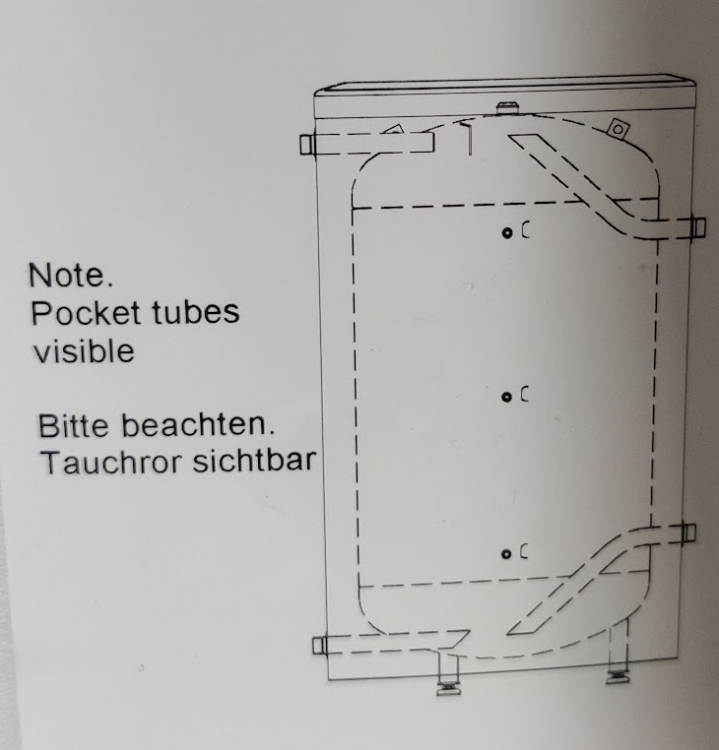
To hand, I have the labelling on the tank itself, which this is a photo of: In the paper work, somewhere, there is the same image but with a little more detail. It's only used in a schematic showing the plumbing options, so isn't intended to be a set of engineering drawings of the internal details, but if I find it I will post it.
-
Equal, within a degree, at the times they should be. Unfortunately the thermocouples I have are +/-0.5° accuracy. But that's close enough for me. How about yours? I hadn't appreciated you had a 4P buffer installed. Is it designed for stratification? What's the model number? what ASHP have you got attached to it? and how are you controlling it?
-
A heating system that is working as designed. It's normal to assume things work as they are designed unless there is evidence that they do not.
-
My ASHP requires at least a 90l buffer. I can't imagine there are many people that have room for a 100l buffer, but not a 200l buffer. And what works for me heating 420m² of UFH and +1650m³ of thermal envelope, with a 200l buffer, will likely scale up or down to suit different requirements. And your evidence is?
-
Stratification is a fairly robust phenomena. A cold 4P Buffer, that is designed for stratification, will go straight into stratification when the ASHP switches on and warmer water is pushed into the top. That less dense water will sit on top of the more dense colder water in the tank. In a short time, once there is sufficient volume of warm water for the port taking water to the emitters to be fully enveloped in that warmer water, it will start to make its way to the emitters. There is a small delay of warm water getting to the emitters compared to a non-buffer, Parallel 2P, or Series 2P in Return line setup, but it's negligible. It does not however require the buffer to fill completely with warm water before that warm water is fed to the emitters. Once the stratification is running, the incoming hot water "slides" across the cold water below and out of the flow port to the emitters. Since the ASHP will not be under-sized for the load, the buffer will then fill with flow-temp water. All that happens as the buffer "charges" is the thermocline plane travels down the buffer, increasing the volume of flow temp water, and reducing the volume of cold water. Once the thermocline plane breaks the return port to the ASHP the return water temp will increase to what was the ASHP flow temp. The ASHP flow temp will then increase accordingly, trying to maintain its 5° delta and if the target flow temp has not been met the process will repeat stepping the flow temp up circa 5°C. If that new flow temp exceeds the target, because the ASHP can't modulate any lower, the ASHP switches off. If the ASHP switches off, the heating load is lower than the ASHP can modulate down to, so flow rates are quite small. I can't explain why the Idronics article doesn't consider this and only considers flow rates at their Max for the given heat pump, but with no heat demand - it doesn't appear the author has understood the logic. On my Nibe F2040-12 heat pump I seldom see flow rates above 5l/min during a space heating cycle, once it has stabilised after initial warmup, and it reduces to around 1 to 2 l/min before switching off. To me that means the heat load at that point is requiring less than the 2l/min flow rate at that point. With a fully charged 200l buffer, that will last over an hour without needing the ASHP to restart. There are loads of opportunities for poorly designed buffers to be specified, or incorrectly sized buffers to be specified, or poorly matched buffer port/pipe sizing to ASHP flow rate to be specified, so I'm sure there are lots of examples where levels of stratification are less than ideal. It's why I said: I can't speak for other manufacture's buffers, but I can see from my own Nibe buffer (and the diagrams of the internal porting that came in the paperwork) that there has been a lot of development work done on the internal porting to ensure minimum disturbance to the stratification.
-
I've never found a single site that will walk you through the design process, but this is a good place to ask questions and gauge opinions. If you were to use "cost of install" to order the different options, then I'd suggest the following order, and suggest you shouldn't go up the order unless you have a reason to do so. The pros and cons are a brain dump, certainly not exhaustive and more judgement that evidenced: 1. No Buffer, ASHP plumbed directly to heat emitters Reduced options for zoning A zone with minimum volume stipulated by ASHP manufacturer must always be open to ASHP Emitters will "switch" on and off with cycling of ASHP. ie. load demand satisfied intermittently, requiring a higher flow temp, stopping system from taking full benefit of weather compensation. Hot water for defrosting taken from emitter circuit during space heating cycle. Colder return water from defrost pushed into emitters. ***My assumption that system does not switch over to take heat from UVC Small flow temp hysteresis required Requires high confidence in heat loss calcs and ASHP sizing. Space heating and DHW demand, incl. expected DHW re-heat times, need to reasonably complement each other. 2. 2P Buffer plumbed in Series Flexible zoning options to react to transient load demand due to dynamic external factors, ie. solar gain. Correctly sized buffer allows for proportionate actuators for all zones Emitters will "switch" on and off with cycling of ASHP. ie. load demand satisfied intermittently, requiring a higher flow temp, stopping system from taking full benefit of weather compensation. Hot water for defrosting taken from emitter circuit during space heating cycle. Colder return water from defrost pushed into emitters. ***My assumption that system does not switch over to take heat from UVC Small flow temp hysteresis required Additional standing losses which can be reduced as far as possible by locating within the return line. Higher output ASHP can be selected than required for Space Heating demand to support better DHW performance 3. 2P Buffer in Parallel Same advantages/disadvantages as 4P Buffer, may be less efficient than 4P due to potential disturbance of stratification? 4. 3P Buffer Same advantages/disadvantages as 4P Buffer, may be less efficient than 4P due to potential disturbance of stratification? 5. 4P Buffer Flexible Zoning options to react to transient load demand due to dynamic external factors, ie. solar gain. Emitter circuit hydraulically separated from ASHP circuit requiring an additional pump for emitter circuit. Hydraulic separation allows emitter circuit to remain circulating, when ASHP has cycled off, allowing load to be satisfied continually with a lower flow temp, allowing full benefit of weather compensation. With a store of warm water that can supply the emitter circuit at ASHP flow temp until tank is almost fully depleted, much longer ASHP cycles can be achieved. Additional lower energy emitter options can be included simply, and provided with ASHP flow temp water when ASHP has cycled off ie. Wet duct heater/cooler in MVHR, fan coil heater/chiller. Hot water for defrosting during space heating cycle taken from Buffer. Warm water can continue to be pushed to emitter circuit, although buffer will deplete quicker during defrost cycle. Larger flow temp hysteresis can be used to further increase ASHP cycle times. Additional standing losses. Although on average, while operating, the tank will be 50% depleted so the ΔT used to calculate the standing losses should use the mean temp of the flow and return range. For a low flow temp system, standing losses are quite small, only cost 33% of the loss to power the ASHP due to SCoP, and are leaked within the thermal envelope. Higher output ASHP can be selected, than that required for Space Heating demand, to support better DHW performance. For me, a 4P Buffer needs to be well designed and correctly matched to the ASHP to get the best out of it. I personally relied on a manufacturer approved configuration from a big brand manufacturer that made both the ASHP and buffer, in the hope that their R&D budget developed a buffer that was well designed and correctly matched.
-
Insulated Concrete Slab Garden Office - Questions
IanR replied to Ticky's topic in Garages & Workshops
On the proviso the floor is unheated, I'll hold my nose and say "Yes". If you plan an electric heat mat, then you really should double it, at least. I would include a 50mm thick perimeter upstand, chamfered at the top, as I detailed in my original sketch. -
Insulated Concrete Slab Garden Office - Questions
IanR replied to Ticky's topic in Garages & Workshops
None of those show it as load bearing, ie. they show a "floating" concrete slab that stops short of (and insulated from) the perimeter wall. The loads of the perimeter are taken down to a strip foundation. The BBA Certificate for Celotex GA4000 shows the same. You are showing it used for an insulated raft, where the raft supports the perimeter wall. Typically EPS/XPS would be used for this due to it's better long-term compressive strength and that it does not absorb moisture. It is less insulating, so a greater thickness of EPS is required to achieve the same U Value as PIR. Edited to add: A link from one of your links quote: Ref. https://insulation-uk.com/floor-insulation/ground-floors/concrete-slab-floors -
Insulated Concrete Slab Garden Office - Questions
IanR replied to Ticky's topic in Garages & Workshops
Taking a step back, before considering a finished floor, level with outside ground, what Insulation are you considering under the slab? 75mm is low for any insulation product, but my concern is that you are thinking of using a PIR/PUR insulation. If so, have you found a product that has the compressive strength to be load bearing as you have it shown? It would be typical to use EPS/XPS for a loadbearing requirement and EPS100 or above can do what you are showing, but 75mm of EPS is a really poor level of insulation, even on an unheated floor. With regards the Finished Floor Level, I feel you'd need to build it like a basement, up to 150mm above FFL, and you've still got some work to do to detail the threshold of any doors. For the basement option, I'd look at how an insulated raft with ICF basement is detailed. You'd "just" need one course of ICF formers around the perimeter. -
No, thankfully mine stopped at the Phase 2 when nothing else was found. They do appear to be pushing for a few conditions on your planning approval that requires them to book some labour hours and lab time at your site. You should try and take control of the outcome and when you submit the report also provide you own summary of the pro-active actions you intend to take. Have you got a Statement of Work from an Asbestos removal company for your site, I'd repeat that verbatim so it's clear you are taking it seriously, and then suggest the ground works team will be tasked with visually checking for and reporting any further unearthed contamination, for which you will bring in the necessary Geo-tech team to analyse and identify the contamination plus recommend remedial work. My report did include a couple of pages of "recommendations" that was just general advice to the builders etc. If you have similar I'd be rewording that and saying how your going to do it all, with bells on, in the hope you don't get a condition requiring further ongoing assessment.


