


JohnMo
-
Posts
13292 -
Joined
-
Last visited
-
Days Won
200
Everything posted by JohnMo
-
Is it a knock down and start again or do you need to reuse?
-

Another 'Cool Energy' heatpumps thread
JohnMo replied to HughF's topic in Air Source Heat Pumps (ASHP)
To get full instantaneous CoP you need dT, flow rate to get the work done. If you have a buffer you will need to take account of buffer distortion across buffer, when doing the calculation. You also need all the electric inputs, on the heat pump, any external circulation pumps both secondary and primary if you have them and power input to controller(s) to work out Watts of electricity used. All this needs to be accurate, rounded numbers are good enough. Just looked at the feeds and it's one decimal place on temperature and electricity and two places for flow rate. -
Another 'Cool Energy' heatpumps thread
JohnMo replied to HughF's topic in Air Source Heat Pumps (ASHP)
Some really impressive CoP and SCoP numbers, but you really have to check them over, some on there only record some electric data, and miss internal units out, which is needed to actually calculate the CoP. Seen a few where the unit runs great and good CoP while running, but electric input stops with compressor cycle stopping, but the unit is still pump 10L/min, running the controller all at 1W input. Also while doing so recording a cop of of about 10. Other are getting a genuine SCoP of 5+. By using well sized units, tuned well and that modulate well and have super long run times. I have one it's great to actually compare what you think, and what real happens. You will be surprised how much standby time can kill real day to day CoP. -
Insulating a shed for laundry room?
JohnMo replied to flanagaj's topic in General Self Build & DIY Discussion
I have all my water treatment outside in insulated shed. Pipes as they transition out of ground are insulated. Initially used a tube heater and zero issues down to -9. Now have heat pump flow and return going through shed so no longer use the the heater. Just insulate all surfaces - 25 to 50mm PIR insulation will do. Use carpet spray adhesive to stick to walls between battens used to make the walls. Add a couple of vents and a tube heater or 2 with built-in thermostats. -
Insulating a shed for laundry room?
JohnMo replied to flanagaj's topic in General Self Build & DIY Discussion
Yes. But getting a plume kit added may be simpler -
Another 'Cool Energy' heatpumps thread
JohnMo replied to HughF's topic in Air Source Heat Pumps (ASHP)
So just straight badge engineering? And selling product, sell heat pump and tell the purchaser You Need a Buffer, because some added it to a drawing and we can't be arsed to change it. Great -
It's pretty simple a big backwash filter to get rid of sediment and to treat iron, then a 10 and 5 micron filter and UV filter. Between pump and treatment there is an accumulator with pressure switch to start and stop pump. Service Drain down system, check and set pre charge pressure on accumulator, check settings on accumulator pump stop/start switch, replace UV filter. Backwash filter check media for breakdown and levels, top up as needed, check functionality of backwash system. Also included is drive time and fuel milage - part share with others in the area getting a service the same day
-
Another 'Cool Energy' heatpumps thread
JohnMo replied to HughF's topic in Air Source Heat Pumps (ASHP)
Why and if cool energy say so, why again? They just aren't needed -
Best looking MVHR valves?
JohnMo replied to Alan Ambrose's topic in Mechanical Ventilation with Heat Recovery (MVHR)
Gee £75 each - my coanda nozzles, got 6 off them, they are Zehnder Circular Coanda Dia 90 mm, White, £8 each, the adjusters are another £18 each if you need them, I needed 2x. Plus I didn't need 6x 125mm nozzle adapters and they reduced duct lengths by over 20m. -
Install a pair of boilers and cylinders
JohnMo replied to allthatpebbledash's topic in Boilers & Hot Water Tanks
S and Y plan, just use boiler at a single flow temperature, so you loose any gains in efficiency from running a two different flow temps - one for DHW cylinder heating and another for central heating. X and W allow two different flow temperatures and priorities heating DHW. -
MVHR options and layout for small flat
JohnMo replied to Bryn P's topic in Mechanical Ventilation with Heat Recovery (MVHR)
Wouldn't get bogged down, small footprint flat will not suffer from being too dry in winter. Big house only a couple of people in it, does. Set to building regs and move on. The layout as you have shown looks fine. Mount MVHR on a well damped surface. I used 2x 18mm ply full wall height and it works well by bedrooms. Or buy avm mounts Coanda effect nozzles are good - flow follows ceiling, so gets to room temp before coming down. Zero draft. -
That is doable. It's all part of the heating system so capacity gets added to system volume and expansion vessel works on system volume. A heat store (thermal store) works with a boiler. But not a fan of pre plumbed as they normally have a load of tat included, you will never use and you have to pay for. Some alternative at a better price point and maybe way better performing, can be specified with a 6.3m² DHW coil on a 300L cylinder. https://thermal-store.co.uk/thermal-store-price-lmt.php Use in house, gas is 6-7p to heat things up, electric 27p per kWh and export is 15p, so why heat stuff with expensive electric.
-
Zone why? Is there a specific need. If a single zone can call for heat how is your heat source managing flow do you have a bypass or buffer etc? To balance I simply opened all flow meters fully. This gives heat source freedom to flow what it needs to get the correct dT. Then if a room is too warm, you reduce flow to increase dT across that loop(s). Decreased flow increases dT and therefore mean flow temperature decreases, decreasing floor output. If whole house is too warm decrease heat output from boiler or heat pump. If house is too cool increase output temperature and get house stable, correct warm rooms. Leave 24 hrs min between setting changes. The house will use about the same energy setback or not, as the heating has the increase fabric temperature after setback. If using a heat pump, this requires higher flow temperature and loss of CoP.
-
Insulating a shed for laundry room?
JohnMo replied to flanagaj's topic in General Self Build & DIY Discussion
I would add vapour barrier, to the inside. To keep room moisture away from insulation and the wood. -
Best looking MVHR valves?
JohnMo replied to Alan Ambrose's topic in Mechanical Ventilation with Heat Recovery (MVHR)
Honestly, once you have been in the house a month you never look at them. If you asked my wife what they were like, she would have no idea. Important to me was the extract terminals could take a cone filter and was easy to replace. That keeps loads of dust out of the ducts. Yes just about any 125mm valve will fit any 125mm adapter. -
Another 'Cool Energy' heatpumps thread
JohnMo replied to HughF's topic in Air Source Heat Pumps (ASHP)
Anti freeze functions are generally always on and manufacturer that allows you fiddle with settings are rare. Same with defrost. Use of glycol has nothing to do with antifreeze settings really, Glycol would be used to remove risk of prolonged power cut and prolonged below zero temperatures as well as same time -
If you are controlling the two down stairs manifolds as a single zone, you do not need actuators on the manifolds at all. All you need to do is start and stop the pumps. This is done via the pump outlet of the UFH controller - use one controller and take a second power signal to the other manifold. Then you have one thermostat calling for heat for the whole down stairs. But maybe better install several thermostats and allow either to call for heat, any thermostat starts the pumps. Any cold spot is likely to be followed soon after by other ones, so allow whole downstairs to run. With buffer you get hydraulic seperation so you don't even need two port valves in the system. Upstairs. Maybe get a simple stand alone wireless thermostat - something like Computherm Q20RF, very adjustable, come with free standing and wall brackets. LLH are something for industrial systems and need very careful sizing avoid. Your boiler if you add an outside temperature sensor will manage that for you, you should be able to set at say 15 degs outside temp switch off heating. But I would also add a WC curve, say start at 20 outside flow 20, so the boiler does nothing when it's warm anyway. Then say 45 when -3. You may have to fiddle with the settings depending on how your mixers respond and house temperature. Set the mixers at say 38 as a safety net only. The idea is the flow temp takes an age to heat up house and then you don't allow it cool too much and the heating just ticks away topping up as energy is lost.
-
Is it worth trying low noise mode in the day time when it likely to be more mild, than at night time.
-
That was all pretty quick
-
Think most will try to hit target temperature pretty fast and once at target ramp down. Vaillant have quite a few settings than manipulate how it runs.
-
For me I have done glycol, pumping losses were huge, then changed it out and did VDI 2035, but decided normal water with an appropriate corrosion inhibitotor was easy to fill, easy to maintain. So now use Adey MC1+.
-
This is something I never even considered. But doing it again would be cheap addition. I did 300mm centres, so only have a out 600m of pipe in 192m² of floor, on 7 loops. Could have easily done extra loops in the main spaces, even if they weren't used and kept as installed spares.
-
I doubt it unless the receipts are all post dated to after planning approval. Also is it shown on the landscape plans.
-
Daikin Altherma 3M heat pump no longer starts the compressor
JohnMo replied to AL Ken's topic in Air Source Heat Pumps (ASHP)
Do you have the control settings, set correctly? Leaving water, external thermostat and room thermostat looks for different things. If you have selected room thermostat and don't have the required interface, it's looking for a signal it will never get. Get the manual out or download and go through everything in the setup wizard, the only stopping it starting is a setting.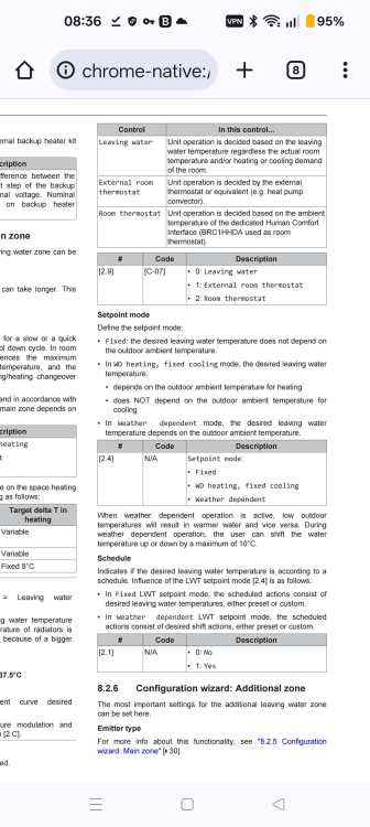
-
Just fill the studs with Frametherm 32, miss out the PIR between studs. Why not make all the studs the same depth? Add packets? Add a breather membrane outside, 25mm PIR inside (do you need it)...



