
JohnMo
-
Posts
12888 -
Joined
-
Last visited
-
Days Won
188
Everything posted by JohnMo
-
A concrete base and a building on top, sounds less than temporary. My house is on a concrete base it ain't temporary. The planning permission will state clearly if PD rights are removed or they stay in place. The OP just needs to read the planning permission documents.
-
I would have as last on my list of things to improve. A kvs of 8 means it will flow 8m³h of water with a 1bar pressure drop. A kvs of 10 will leave the valve hydraulically invisible at heating flow rates even with glycol (you don't have). 8 is near enough.
-
Pipe roughness is about 0.0004k (mm) for multilayer. Copper new is about 0.00015 so smoother. By the time it's covered in deposits that could be 0.03. Your clutching at straws going down that route.
-
No - no affect on ultimate flow rates through system just energy usage.
-
Isn't that because while developing a site under planing permission, there are no PD rights, you are legally bound to develop site to the agreed plans, without deviation. That would be my understanding also
-
Why do you need any electric cables in the roof? Put them in the wall and do wall lights also. Leave the whole roof area open as you want it. You need to think about how your insulation is attached to roof (fixing method) and plenty of other details so trades don't mess up.
-
The issue with volumiser plumbed as is, (if I have understood correctly) during DHW heating cycle, you are also having to heat an extra 100L of water every DHW heat cycle. You ideally have the volumiser in the central heating return only and tee in the DHW cylinder return after the volumiser.
-
 They obviously don't want the work - move on to the next company
 -
I would really concentrate on how get to best heat transfer from pipes to floor. Do it wrong and system performance will be poor. An option is a biscuit mix. Poor heat transfer will require higher flow temperature for the same heat output to room. Not sure your proposal will be good enough, wood is a good insulation so heat transfer not the best. You also need zero air gaps around the pipes. Every air gap will diminish heat transfer opportunity. Get as much insulation in the floor as possible 140mm wood fibre should really be increased to 200mm+.
-
What the two circles, one must be your cylinder what is the other. How does the return piping from the heating interact with the two circles as you only have return pipe from the two circles?
-
So just about the same as @sharpener 28mm of copper.
-
Isn't the norm for motors 4x rated capacity? All the equipment you have listed I would be doing 25mm².
-
Have you done voltage drops calculation for expected loads? Sounds a bit small 10mm²
-
dT is your flow dT from the heat source and is a variable. The bigger the dT the higher the output flow temperature is for a given mean temperature (heating output at radiators or UFH), so ideal is to run a low dT. But you can run any dT you like within reason. But as suggested by Vaillant, flow is king with with a heat pump. You need to get rid of bottle necks. So you need to get rid of pressure drops where practical or add additional pumping power to the system to overcome them, such as a second pump on the return piping run, set at a fixed speed to get full system flow where you need it to be.
-
That's your issue your flow temperature is way to high for current outside temps and a new build house. Your floor output will be huge, your thermostat is controlling nothing else. Now the counter intuitive bit. You need to dial back the temperature, on your curve. This will allow a slower more measured heat input and allow more time for the radiators to back fill any missing room temperature. Low and slow will allow heat to be absorbed the building. Allow system to run without any setbacks or off periods. Your WC should look something like this for the UFH 15 OAT flow 25 and -3 OAT flow 35. This will allow the majority of the heat for the house to come from the floor and your radiators just ticking over. If the house is getting to warm dial back the -3 flow temp 0.5 of a degrees every 24 to 48 hrs. If you do the above you can leave the UFH flow meters fully open and leave the ASHP to control flow and dT.
-
You need to calculate the pressure drop of the whole system. 1 bit of it's a bit meaningless without seeing the whole picture. Have a look here for some guidance https://heatpumps.co.uk/technical/pressure-drops-flow-rates/
-
Just sounds like you need a little balancing done If your UFH is getting to temp and radiators not, your curve for the UFH is too aggressive assuming you are mixing via an electronic mixer. If no mixer, slow the flow rates to each loop in the UFH so it outputs less. Knock 0.5l/m off each loop. Less radiators as they are. What flow temperature do you have set are you running weather compensation or fixed flow temperature?
-
Piping size isn't the only thing affects pressure drop, ball valve strainers can kill flow, I took my strainer cage out and added a full flow filter instead, good improvement in flow, I also replaced 3 port valve for a high kvs one again more flow. Poor selection of anything in the circuit will kill flow. 11kPa is nothing of a pressure drop, so you are loosing head somewhere else. 11kPa is around 1m head loss. Not sure what size pump you have but it should be 6 to 8m head pump. I have a flow rate of around 1320L/h for a 6kW heat pump. So things to look at Valves fitted need to be full bore Diverter valves look at a kvs of over 10 UFH ensure all flow meters are fully open Radiators look at how the lock shields are set and balanced Ball valve strainer, install a proper filter with low pressure drop instead.
-
@Gus Potter The other simple way to run the UFH is again all open system and if thick screed is a simple low hysterisis thermostat or via ASHP controller if it has a built-in thermostat. Set thermostat to 20.5 to 21 and ASHP to fixed flow temp of 32 to 36. And then let the thermostat run the system. With UFH and a new build those flow temps will give great cycle times and run once per day most of the time. Pretty good CoP. Run time will vary with outside temperature. Then you also have room to oversize the heat pump easily, without causing to many issues just incase we get the -20 degs.
-
Panasonic aquarea - dual zone cooling @ diff temps possible?
JohnMo replied to SBMS's topic in Air Source Heat Pumps (ASHP)
But they have to be sized correctly to do that. True You can, but after loosing internet (signal from source - not house internet issue) for quite a few hours the other day, I wouldn't let anything internet based anywhere near the heating system. In most of the UK if you never allow house to overheat, you run at about 13 degs without any condensation issues. -
Glycol is only part of the ingredients in the glycol tub. There is also the corrosion inhibitors etc these may or may not be compatible. Using a car antifreeze as an example, they are dyed a different colour to indicate compatibility i.e OAT (Organic Acid Technology) based chemicals are coloured orange. So you ideally need to match the chemical makeup otherwise you can cause more issues than you solve.
-
Panasonic aquarea - dual zone cooling @ diff temps possible?
JohnMo replied to SBMS's topic in Air Source Heat Pumps (ASHP)
Read a lot of ASHP manuals (yes sad), they all seem to work in a similar fashion. The ASHP receives a zero volt signal to run the second operating temperature, otherwise it runs at normal temperature So if your UFH is only calling for heat only it runs at one temperature, if your upstairs also calling for heat the second set point comes in, a mixer valve then mixes up/down in cooling/heating Work equally well for heat and cooling. You need (generally) an electronic mixer valve, volt free thermostat in addition to what in your fan coils, maybe a buffer or ideally a volumiser to cover just the fan coils calling for heat. Adds loads of additional complexity. -
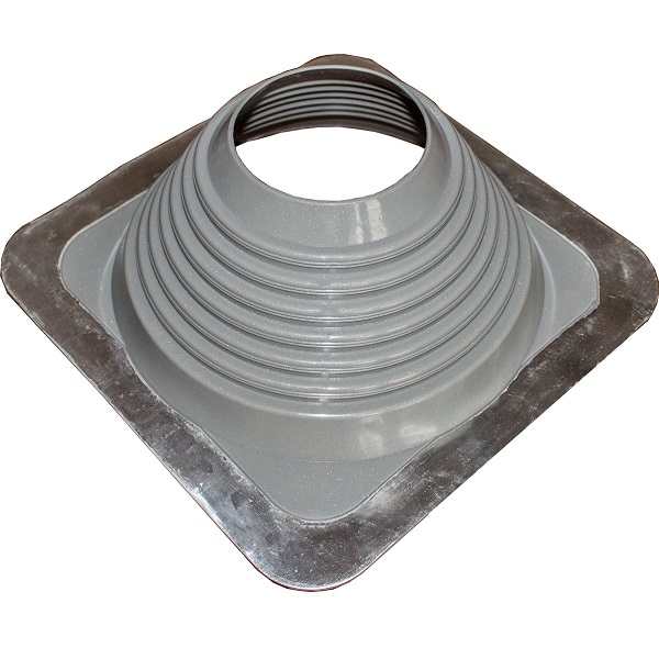
Mine went through cathedral ceiling and I used something like this taped to airtight membrane.
-
Wet underfloor heating laid under wc position
JohnMo replied to Jothetaxi's topic in Underfloor Heating
Just incase, we did that also. Was also concerned about drilling holes through tiles etc. 5 years later no issues. -
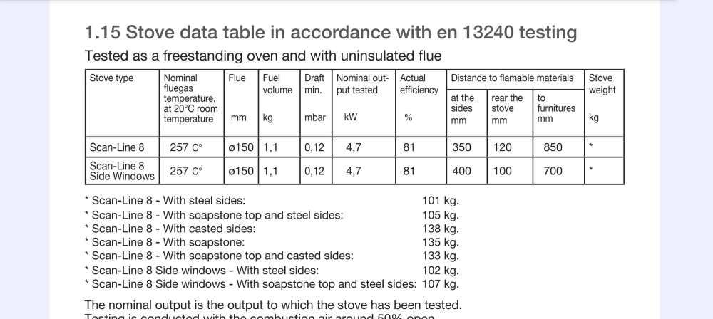
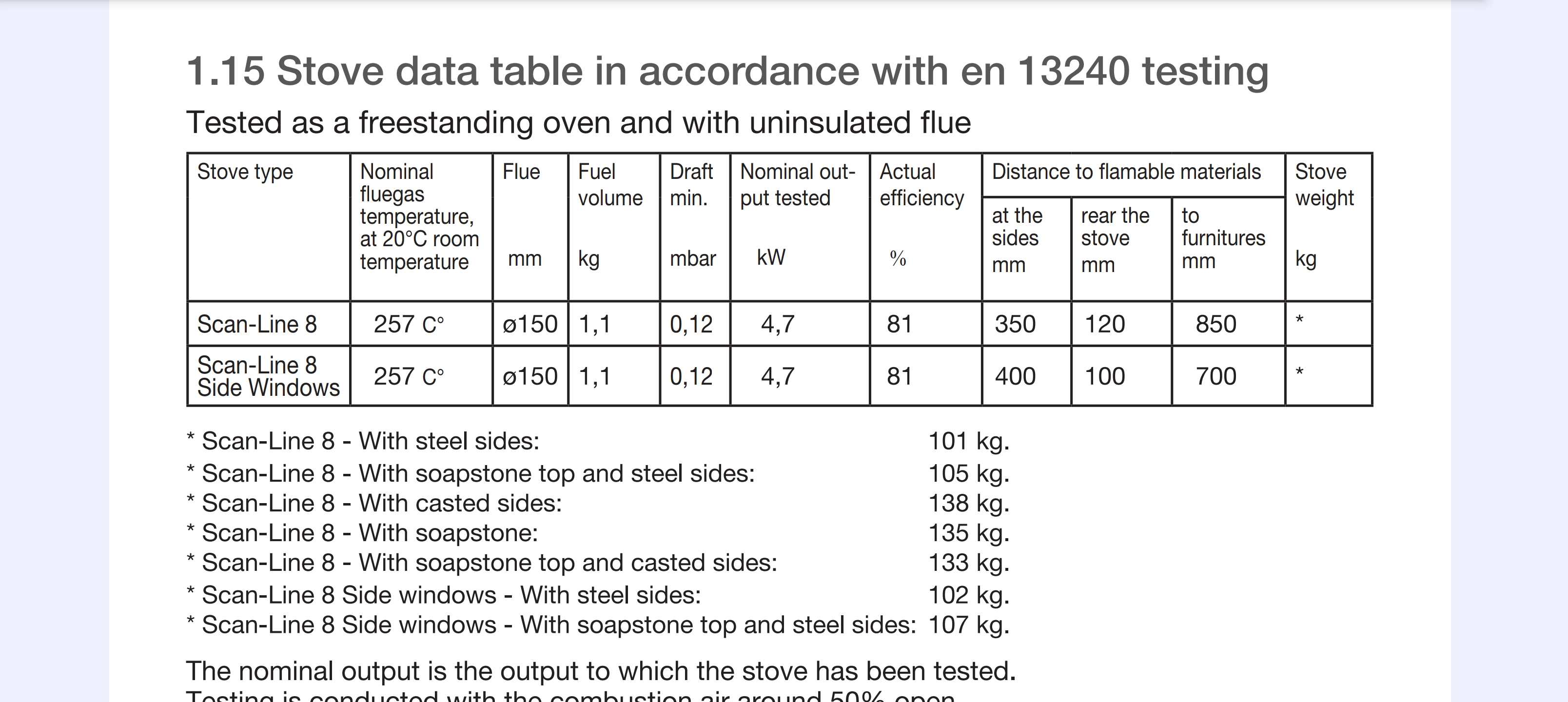
AI may say that, but it depends on the manufacturers instructions for distance to combustibles. Mine for example clearly states 125mm at back and 350mm at the sides