


Onoff
-
Posts
21031 -
Joined
-
Last visited
-
Days Won
206
Everything posted by Onoff
-
OK it won't happen soon but I'm going to plaster my bathroom ceiling (and one half wall) myself. It's moisture resistant, the green stuff. Any pointers? Some prepping I'm guessing, PVA? I've done a bit of wall plastering maybe 25 years ago but never a ceiling. Even then only small areas say a metre wide at the top and bottom of landings. Worse case I screw it up and get the BiL to make good my mess Cheers
-
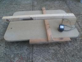
These cry out to be foamed in imho (not trimmed the foil/vcl yet and not the final cabling which will be in 20mm galv):
-
How about spray adhesive? Surprisingly sticky! https://www.screwfix.com/p/no-nonsense-contact-adhesive-natural-500ml/32657 Failing that a "grab" adhesive. Whatever's cheapest I reckon.
-

24V gate - what size cables for 25m in duct run?
Onoff replied to readiescards's topic in Electrics - Other
Imho any underground duct might be subject to condensation internally, more so if the cables run a bit warm. This could conceivably pool at any low point in the duct and affect and cable laying in it. I imagine this is one reason why any cable in a duct should be "duct rated". Paranoia? The regs touch on the issue of condensation, protection against moisture etc. The last bit of duct I ran I even considered running a length of aquarium tube in there so I could periodically pump out whatever, if anything, got in there. I even considered punching some drain holes mid point in the duct, wrapping in landscape fabric and packing gravel around it before concreting. Of course then I worried about the water table etc so in the end did nothing! I just ran everything in 20mm conduit and kept those together with some black dowpipe for neatness when concreting. Just noted that photo was taken in June 2014 @readiescards and it's still not finished! Tell your missus -
What dia Nichrome have you gone for? I faffed making one with Kanthal wire from an online vape store. Although it worked for a bit the wire kept breaking and I burnt the wall wart psu out! I had even done some rough Ohms Law calcs as well. Figure it needs a constant current psu maybe. Got bored and gave up! Even my missus had a go...
-
Zinga, Galvafroid?
-
24V gate - what size cables for 25m in duct run?
Onoff replied to readiescards's topic in Electrics - Other
@readiescards, you're not thinking 24V DC for a system with solar charged batteries are you? -
24V gate - what size cables for 25m in duct run?
Onoff replied to readiescards's topic in Electrics - Other
This I think is the opener manual: idv0532a01en.pdf Says on page 3 of the above that the MC824H control panel is compatible with the 36W LFAB4024 and the XLFAB5024 50W. And here's the manual for that: D00011568.pdf The control panel still needs 230V AC to it even though the motors are 24V DC I think you'll find. All the cable sizes / run lengths are in the manual on page 2 of the second manual. -
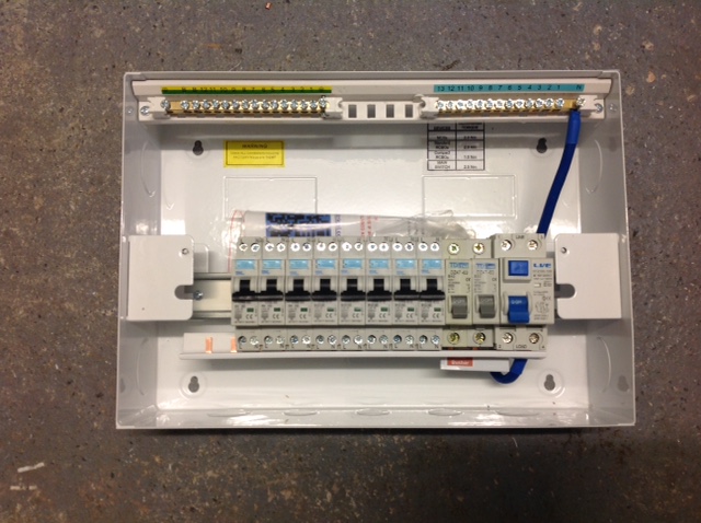
I retitled this "Compact RCBOs" as it's going away from Wylex.
-
For that I'm thinking a big box made from pink plasterboard. Then with the vcl over that.

-
Excuse to build an insulated dog kennel?
-
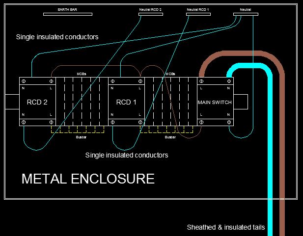
Ah! I didn't realise the board was feeding sub mains. I thought it was an overkill seeing as you are using Compacts hence no fly leads! For others here thinking wtf, consider a metal cu on a TT system. The earthing arrangement is likely nowhere near as good as with TN systems. The incoming meter tails are stranded copper cores that are sheathed and insulated, in effect double insulated but it's actually wrong to call them that even though the sheath is insulating! They will come in through a plastic gland. Quick CAD sketch (in lieu of my earlier fag packet sketch - felt the thread deserved better): You have in the cu for want of a better word "fly leads" from the main switch to the individual RCDs in the case of a split load board. These fly leads are single insulated. They're also pretty flexible by construction. Add to that the modern move away from two screw terminations in main switches to one bfo screw (bad move imo). That's a big bone of contention on the basis it's easy for it to loosen. NEVER, EVER think that these screws are factory tightened properly, always check. So with potentially dodgy single screws and springy, single insulated, flexible conductors, if one comes adrift it could easily touch the metal enclosure...and that's BAD! Wasn't a huge issue before when a TT enclosure had to be made from "plastic". So the way round this, in a TT is to fit an upfront TD RCD in place of the normal DP main switch. Wire comes adrift, touches the case, TD RCD trips. The 100mA rating is there to give fault protection for the single insulated cables that feed the 30mA RCDs. If you put a normal, no time delay 100mA RCD in front of the line of 30mA RCDs it doesn't guarantee it won't trip first hence the time delay element. Only a TD 100mA provides proper discrimination. There's a lot of confusion over time delay but think of it like this: A fault occurs on an outgoing circuit in excess of 100mA you would think that it should trip the 30mA RCD first if that's before a 100mA RCD. But normal BS EN RCDs (& RCBOs) only have to trip within 300ms. The issue is that the 100mA RCD if non time delay may react quicker than the 30mA RCD. Making the 100mA RCD time delay gives the 30mA a chance to trip first. Hope that makes sense. If you look at the SBS Compact assembly the bus bars take the place of the single insulated fly leads. They're affixed at multiple points and can't really come undone and spring against the enclosure.
-
It's a belt and braces thing I believe as the double bus bar takes care of a big "worry" but I'll let Dave comment.
-
Hello Dave, first post! You might want to introduce yourself on here. I'm sure you'll get a few questions direct now!
-
'Kin how much???
-
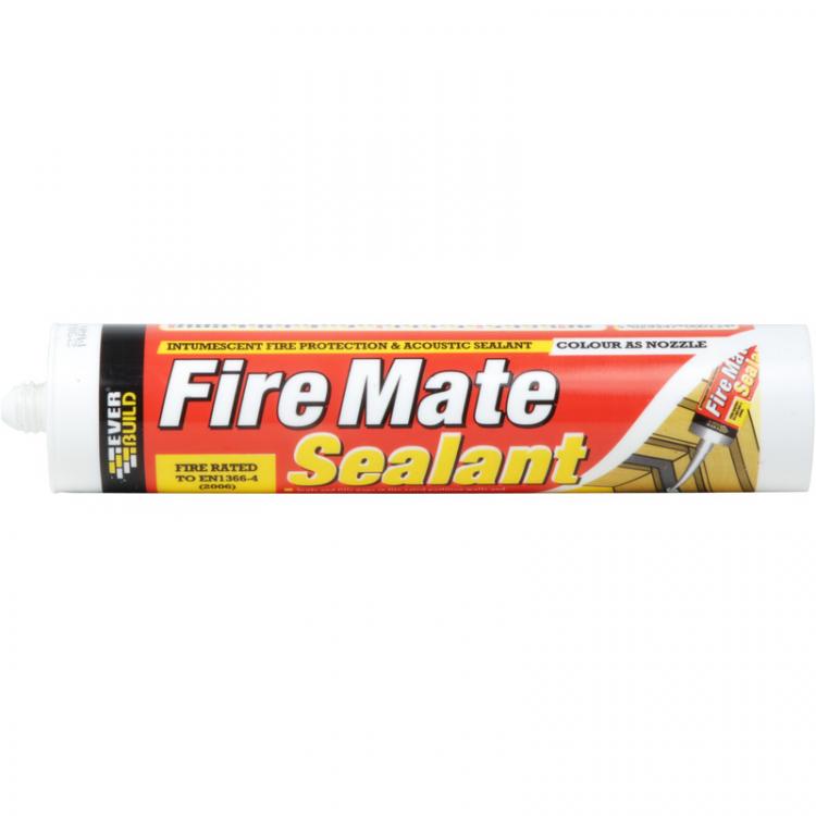
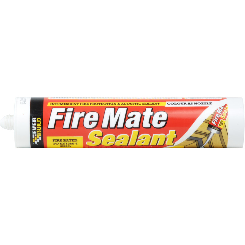
Probably but I was aiming for something intumescent. I have a few tubes of this I was hoping to use: Says it's "tested for air permeability to EN13141-1" whether that has any bearing...
-
Yes. The picture below from SBS shows a line of Compact RCBOs on the left then two MCBs before the main switch. Subsitute full height RCBOs for the breakers: The busbar along the bottom is in fact two, one for L and one for N insulated from each other. They pick up from the main switch. Only the Compacts are fed like this. The full height RCBO's (or mcbs in this case) are fed conventionally.
-
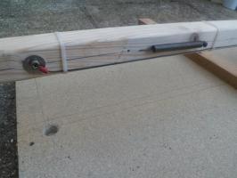
That'll be a laugh trying to cut they the foil but not the vcl! Going to give it a go though. Conduit will enter through the hole in the bottom of the hood. It'll need a bead of something around that too. Then all I have to consider is the losses through the conduit itself! Might gel it where it comes up into the conduit box. Taking the Tesco, "every little helps" approach!
-
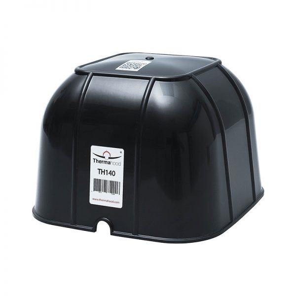
Just about to puncture in earnest my lovely plasterboard ceiling for 5(6) downlights and in particular the continuous vcl that sits above the moisture resistant plasterboard. I've had it planned to do like this for a while but will my idea to maintain the airtight layer work? So, between the joists its fully filled with 100 + 50mm of foil faced PIR. I'm using TH140 Thermahood downlight covers that measure 185 x 185. A rigid plastic type they are. They have no bottom flange really as per the sketch (the circular ones do but I like squares). So I drill up from below my 60mm dia hole that goes through the plasterboard, vcl and into the foil faced PIR a bit. Then with a long series pop a hole up through the PIR. Into the loft with my 200x200 wooden jig, centre over the hole and neatly cut out the PIR. At this point I have the opportunity to LEAVE the bottom layer of foil intact as the PIR just peels away. That is above the vcl. Ideally though I want the vcl outside the 185x185. So I cut back an exact 185x185 section of foil and vcl and centre the Thermahood over the cut out. I figure just a bead of intumescent sealant around all 4 sides should do the trick or should I invest in some airtight tape? To maintain the insulation I'll be adding a 150mm deep slab over the hole area above the downlight. Plenty of height to do so in what is dead space. There's a good 300mm between the tops of these ceiling joists and the underside of the dormer extension floor joists. Do I need to fill the void outside the tapered sides of the Thermahood? Low expansion foam maybe? Or can I leave this void unfilled? Thinking condensation maybe? Cheers.
-
Build it Live - Kent County Showground, Detling, Maidstone ME14 3JF
Onoff commented on AndyT's event in Community Calendar
-
SBS DP Compact, single module RCBOs go to 40A. SBS do the bigger, standard height 50A RRCB-B50L. This has flying neutral and earth leads and is £12.
-
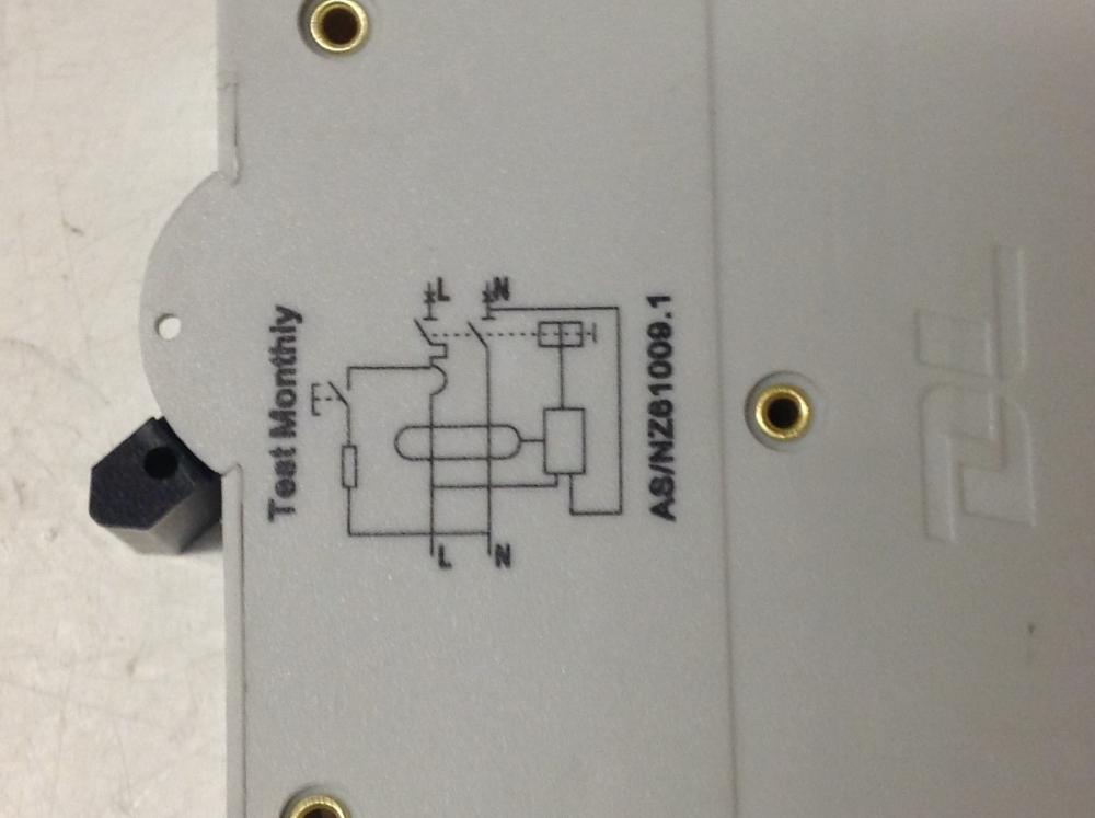
Schematic on a typical SBS Compact RCBO: This from Dave at SBS: "The GARO is a true 2-pole device, but its biggest size is 25A. Probably couldn't achieve 6KA at bigger sizes. Couldn't therefore deal with 32A rings or 40A showers. It is LIVE IN at the bottom only, which shouldn't be a problem in the UK."
-
Choosing casters - is a nightmare. Have you any advice?
Onoff replied to ToughButterCup's topic in Tools & Equipment
Option 2 -
Choosing casters - is a nightmare. Have you any advice?
Onoff replied to ToughButterCup's topic in Tools & Equipment
Bolt the castors on using nyloc nuts rather than screwing them on. -
Choosing casters - is a nightmare. Have you any advice?
Onoff replied to ToughButterCup's topic in Tools & Equipment
Swivel casters all round for easy shifting. A couple of those being lockable ones if you ever bring it inside the house. Nylon wheels are cheapest but noisy and can mark some floors. Something like this: http://vi.raptor.ebaydesc.com/ws/eBayISAPI.dll?ViewItemDescV4&item=183012234509&category=26224&pm=1&ds=0&t=1516081030000&ver=0&cspheader=1


until