


joth
-
Posts
2913 -
Joined
-
Last visited
-
Days Won
5
Everything posted by joth
-
Slightly different situation, but a near-neighbour installed a 14kW split system Ecodan and when it's driving the UFH he finds it can't modulate low enough so is constantly short-cycling, and only achieving COP of 2 or less. He's working on a claim under MCS to get it replaced as it's over specified for the property. So while oversizing is fine for heating a cylinder, also check it won't be too much for the heating circuit.
-

Hello! Two-bed new build and builder slow to quote
joth replied to Christian181's topic in Introduce Yourself
A colleague did a major renovation (the inspiration for own own project, in fact) this way: everything was open-book and indeed managed through BuilderTrend. Both aspects of this suited them very well, as they wanted a lot of control over design elements that could only be decided as it progressed, and having the app give full visibility of the process start to end, including what they wanted done each stage and how much it would cost before it happens. One snag was he (as client) had to take control of the "architect" / contract administrator role in the app to keep things moving at a reasonable pace. Fortunately his brother was the architect/contract admin so the trust was there to make this work. (No idea if the builder ever new this is what was going on). I know from our own project the 3-way builder-architect-client decisions can be painful. (But I find much worse the situation we've had once or twice where architect approves a change without looping us in, and then a month later we get a surprise bill for thousands on work changes we would have preferred having input into, or at least advanced warning of. BuilderTrend REALLY should solve that problem at source. I wanted to use it before we set out, and would definitely seek to make that a requirement of any future job like this). That said, no idea if it's because of my colleague's tastes, the fact they just weren't super cost-sensitive, or because of the area (London) or what, but their project did end up well over double the initial agreed budget. So while going open book gives visibility on price, it is not necessarily better for controlling it. -
It's not the question you're asking, but quite related: make sure the toilet bowl you purchase is "low cistern" compatible. Unfortunately there's no standard marking to tell you this, but the bathroom sales guy (earning his fee) warned us that modern "whirlpool" style rimless bowls really need a bit more drop to get enough speed up to really work. (And then, they really work very well). Also, a higher cistern means you can leave the lid up and still get at the flush button (This is either a feature or a bug, depending on your outlook). Anyway these are the reasons we got pushed to 120cm cistern, and redesigning the boxing in to deal with it.
-
Agree, majority of our quotes are ex VAT and indeed handled via a main contractor so it would be very difficult for them not to pass through the VAT savings. The one wrinkle on those is where we've already personally put down deposits inc VAT (mvhr, windows, internal doors) we won't see that tax back. Had our contractor paid deposit and not yet billed us it would be a different story. I'm sat on numerous other quotes wanting a deposit (bathrooms, kitchen, ashp) so will hold off on those for another few days now. The main place we'll be going to consumer retailers is kitchen appliances (Curreys, JLP etc) so aggressive online price comparison could yield some results. We won't need those until November or so. And some fresh furniture in the January sales ? All that said, bet he won't drop it.
-
My local installer was happy to quote supply and install for the 8.5kW with matched Ecodan 300L tank. That was his default suggestion, in fact. In the end I switched it out for the OSO Geocoil tank which actually reduced the quote and also reduces standing heat losses.
-
Full VAT, full fat renovator here. Please, don't get my hopes up of yet another VAT saving we'll somehow manage, through extreme ingenuity, to maneuver ourselves out of [Current 30% of our way through the spend, having just shelled out 13% of our total spend in the last 24 hours...]
-
Panasonic have the PAW-FC-D15-1 at list price for £230 which I think is totally reasonable, if I can just find someone to supply one https://www.dysk.co.uk/wp-content/uploads/2019/06/Dysk-Panasonic-A2W-Price-List-2019.pdf
-
And even less if you have an export tariff, in which case you'd want to use the market spread - difference between average "buy" and "sell" prices. So about 10p/kWh On the other hand, the point here was batteries allow a system design where ASHP will maximize its contribution to DHW needs from the PV, rather than using the immersion, so allowing the COP of 3+ to come into effect, which does provide a little more economic up-side. Still, at this point anyone installing it is doing so for more than pure economic value alone. (Be it environmental, or the benefit of grid failure backup - which itself maybe an economic justification in these days of home working)
-
To be fair, this is "how much battery storage can I get for £13,000?" which if very different to "how could I usefully spend the £3000 I save by not going with a sunamp?". To the latter, I think 2x PylonTech US2000B plus an inverter and installation might be possible around £6-700/kWh? (And easy to add more storage in future as prices drop).
-
@davidc In the U.K they come with cooling disabled. Cooling can be enabled by adding a "coding resistor" Once again, @Dan F knows the products better than their own sales people.
-
^ all of which is to say, your question is a very good one and I'd also be interested to know if anyone has experience of this with the Vaillant too :-) But don't hold your breath waiting to find an installer that will give a straight answer!
-
AIUI this varies a lot based mst of all on the installer, rather than the manufacturer. Some will do it without batting an eyelid, some will insist "metering for usage" needs installing, some will tell you you're breaking the law and deserve to be put in jail if you enable it. RHI itself is now clear that colling is allowed, but the payments will only be made based on predicted heating use. (Or actual heating use, if they require you to do metering for usage) some manufacturers go to greater lengths than others to permanently disable cooling, so the above is based on ones where it's broadly possible. No idea where Vaillant sit on that spectrum. After going around this several times, my end tactic is to install it without cooling enabled, but make sure I'm with a manufacturer with plenty of track record of ppl being able to DIY enable is post-installation (specifically, Mitsubishi in my case)
-
Absolutely. I actually thought you were talking about self builders that only care about passing SAP and don't believe airtightness has any other value except box ticking. (IIRC someone was expressing this opinion on here just this week)
-
I had a heating/plumbing schematic drawn up last year that I'd like to redraw and adjust myself. Anyone got recommendations for a cheap (free) tool that's good for plumbing/pipework and control diagrams? I see lots of P&ID packages by no idea where to start Years ago I'd have used Visio so a nice replacement for that might be enough
-
This is rampant across the industry though? You hear of big developers failing the test (on the odd house actually tested) so the squirt sealant under all the skirtings so it passes. Then next day the carpet fitters arrive and cut the sealant all out again Honestly no idea how to avoid it really. Airtightness is so hard won and so easily lost, the homeowner can easily destroy it the day they move in without even realising they have.
-
Got it. To be honest the photo looked alien enough I didn't even try and understand what I'm looking at. The instruction manual is clear the element must have thermostat and emergency cut off, and should not be replaced with a different manufacturer's, so the fact the manufacturer does rate this 4.5kW one for use in this tank seemed like it should meet those requirements . Like you I can't see if from the photo though.
-
So long as you have a single contractor this is possible, but if you are employing the subs direct you need it to still be unoccupied the day each of them starts.
-
As I understand it this scheme is not administered by the HMRC but by the contractor(s) you use for the work. So long as you can convince them it is unoccupied the day they start, and it has been for 2 years, they can choose to charge the reduced rate. If you have multiple contractors you need to do this with each of them. There's no mechanism to "claim back" any overpaid VAT. Your tender docs should very clearly require this from the contractors If I'm not totally wrong, it means the SE work was full vat and can't be changed now, but the main contractor work is completely independent and not impacted by that. I'd be more concerned about the lack of hard evidence of it being unoccupied. Showing a builder your Google location history really doesn't prove a thing, I'm afraid. You have to prove *nobody* was living there, not just that you weren't.
-
1/ The immersion has it's own stat plus emergency cut out 2/ it has a built in thermostat for the indirect heat source, midway down the coil 3/ it has a pocket for optional heatpump thermistor above the coil (next to immersion pocket) https://osohotwater.co.uk/content/uploads/2018/10/OSO-DELTA-DGC-MANUAL-UK-142226-00A.pdf If the heatpump thermistor is used for "fine control" the standard stat effectively becomes a high limit cut off I also have a few DS18B20 I was thinking to attach to various pipework outlets for logging, but could perhaps be used for finer control too in future if really needed.
-
I checked, they recommend 4.5kW max, and that won't invalidate warranty https://www.oso-spares.co.uk/immersion-heaters/45-kw-immersion-with-2-x-4mm-cables
-
The 17 pages here with no clear answer provided the clear "no" answer for me, as after the thrill of researching and installing the system, I honestly never want to have to think hard about it again, and the risk of unscheduled maintenance seems too high. Likewise I eliminated the Mixergy tank for over-complexity. Getting a reliable knowledgable ASHP installer in our area is damn hard, without making an extra stick for my back. Instead, for better or worse, I've settled on an OSO geocoil: https://www.osohotwater.com/en/domestic/delta-geocoil 300L with claimed 49W heat loss is just over 1.1kWh per day, so not entirely out of the SA domain. But with massive benefit that every single heating engineer in the country will know how to hook it up or work on it, and even if OSO go bust I've got a very good chance of long term maintenance on it, as there's virtually no active components in it. (Much less any cloud dependency, no thank you Mixergy). It's also actually cheaper than the Ecodan matched UVC my installer originally quoted for, so if all goes well it's exceptionally good VFM. Biggest downsides vs any other UVC are it's only available with one immersion heater slot (so I am reliant on ASHP for reliable reheat times, unless I can retrofit a 6kW+ element?), and there's always a risk about longevity and unrepairable nature of VIPs (OSO say it's no more likely to fail that the tank itself leak, and they have 25yr warranty).
-
What electric heating and DHW for small new build flat?
joth replied to Mr Punter's topic in Other Heating Systems
I'll say it once more: put any spare £ you want for hugs from planet earth into insulation. That stuff is hard to retrofit, especially underfloor. This will reduce heating (and cooling) requirements at zero incremental cost over time. Systems changes, PV or ASHP or whatever, can be retrofitted far more easily as/when that becomes economic. But if you've already reduced the total energy demand, it matters far far less where that energy is coming from. To reappropriate the physical wastage slogan for energy efficiency, the priority order should be 1/ Reduce energy requirements (i.e. add insulation), 2/ reuse energy (i.e. increase airtightness and use heat-recovery ventilation), 3/ recycle energy (more accurately upcycle energy: convert low grade energy to higher value, e.g. via PV or ASHP). SAP seems to encourage everyone to think about #3 without doing #1 and #2 first. -
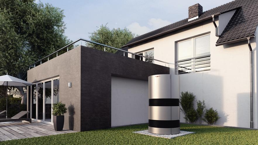
meta comments - you mention "vents etc?" and that got me thinking about MVHR placement and air duct routing, but to confirm the question here is actually solely about ASHP? (co-locating them maybe necessary anyway if going for a fancy integrated heat pump ventilation system, or would like to have flexibility to retrofit one in future e.g. if that tech becomes more commonplace by the time the system eventually needs replacing) - having a North arrow on the diagram could be handy (it's towards the bottom left corner). Some assorted thoughts: - even if using a split system, my gut feel would be to put it beside or as close to the house if possible, all else equal, to reduce amount of refrigerant pipework both for efficiency and avoid stupid mistakes with a future landscaping project damaging the pipework - for aesthetics, the main places I'd avoid putting it are on the "main" access path from street to front door, and anywhere in sight of the prime outdoor seating location(s). As a rule they look a bit ugly, so putting it approximately in the same place you'd keep the wheelie bins isn't a bad line of thinking [assuming you're planning to keep the wheelie bins outdoors, but out of sight] - assuming it's not a massive (dual fan) unit, then it could slot under either the "sitting room" windows in the area you mention, or nestle between them, - another possibility to at least work through to consciously eliminate is putting it on the side passage wall , mounted up above head height. It's not a conservation area so I think this is an option, but could have consequences for neighbourly relations. (hypothetically, if were the sort of folks that make a lot of noise out in that area themselves emptying the bins and emptying the yappy dog each night, you'd probably find the sound of a heat pump would be gentle soothing white noise in comparison, but this is a hard point to make). - wherever it is, you'll really not hear it yourself indoors due to triple glazing and having MVHR meaning the windows don't always have to be wide open. (Likewise the noise of any hypothetical yappy dog will also be greatly diminished) And if all else fails, "own it" -unapologetically sling one of these in the middle of the garden:
-
What electric heating and DHW for small new build flat?
joth replied to Mr Punter's topic in Other Heating Systems
Just to check this point, is your concern that qualified engineers, parts/replacements or even the delivery of gas itself will become difficult over time? I personally can't see that happening for many decades, as a nation we're so hooked on it, and it'll need a very very significant change in pricing to really retrofit folks off it. If they're paying people to move off it, you might as well go with it now and take the cash incentive when it's offered. (Plus, there is still the slim possibility we'll see CO2 near-neutral gas someday and there'll be no need to do any of this) Obviously if you preference is driven by deeper ideological basis around this point then fair enough (and I'm with you). For low maintenance at a fixed (low) capital investment, and with an eye to minimizing emissions, I'd say put all the £ you can into upgrading insulation, airtightness, reducing the need for heating of any sort, and then go with the very best value for money combi boiler deal you can find. (As a landlord I found a system boiler a nightmare as our tenants couldn't understand a timer switch and had repeated emergency call outs to adjust it. We fitted a combi boiler and never had another issue) Just my 2p worth. -
This is good news! I was planning to use trimless plaster-in downlighters and worrying about the grumbling this would cause, but if the grumbling is expected even for normal downlighters I think we should be fine https://www.mr-resistor.co.uk/item.aspx?i=15768

