
Radian
-
Posts
2586 -
Joined
-
Last visited
-
Days Won
15
Everything posted by Radian
-
No, down in the bottom right corner of the LCD display, next to the anti-tamper "ratchet and pawl" symbol are the four quadrants showing active +/-A (real) and reactive +/-R (imaginary) power flow direction. The other impulse LED below the buttons is for reactive power. Can't see anyone having a use for that? Of course these "revenue grade" meters eschew the likes of CT's and use volt-drop across known resistances to quantify current. I'd do the same were it not for the invasive introduction of a suitable resistor after the main isolating switch in the Consumer Unit. CT's are a pita due to their non-linearity and phase errors. I compensate as much as I can for these but a direct measurement of current would be heaven. I already poke 240VAC (albeit resistor dropped) into my ADC to eliminate the distortion of a voltage transformer!

-
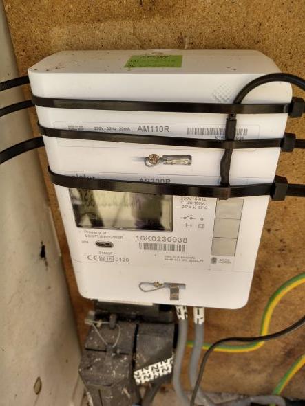
Hi markocosic. The impulse LED on my Elster AS300P is labelled 4000imp/kWh so I'm only expecting it to pulse once every 0.9s for a 1kW load (4000 flashes per hour for example). By observation it also continues to pulse identically irrespective of power flow direction, whether in or out of the Joule bucket region except for when the bucket overflows and the tamper flag comes on the display. Also on the display is a 4-quadrant arrow indicating power flow direction for both active/reactive power. Watching this shuttle back and forth confirms that there is a buffer (Joule bucket) before it overflows. Your'e right about that. I understand that some continental utility meters have such small buffers that burst firing isn't feasible with 3kW loads. I don't think mine is that bad but it sure is behaving strangely. I think you're being led astray by @SteamyTea who is also monitoring power but exclusively using the LED blink method. I have a CT and sample it alongwith voltage to get a real power reading at around 128 samples per cycle. I have been monitoring the impulse LED in parallel to serve as a confidence boost for my measurement accuracy and also to re-sync the bucket when it overflows. This latter step is based on an assumption - having seen the LED sync with the anti-tamper icon on the LCD. I think this refers back to the concept of 'winding the clock backwards' which is analogous to pushing power back into the grid.
-
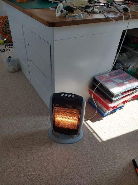
I picked the perfect weather to be using an electric heater as a dummy load 🙄
-
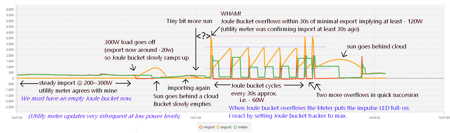
I've just strapped my sensor to the utility meter using tie-wraps: I use the same principle as you to convert impulses/time to watts but under interrupt. It's really quite annoying as the impulses obviously slow to halt at zero nett import/export - exactly where I'm trying to investigate. Apart from the confidence boost it gives me that my own power measurement is accurate, the really useful thing is detecting when the Joule bucket has over-topped and power is going to the grid. But I've really got to get a grip because everything I'm seeing indicates that this 'revenue grade' meter is misbehaving. The 'big picture' of unexplained behaviour looks like this example: The green trace labelled "meter" is the power as reported by the meter impulses. It occasionally lags my instantaneous power measurements (red trace labelled "import") because of the extended time between impulses at low power levels (9s apart at 100W). But the two generally agree i.e. at the start of recording when roughly 300W of import is taking place. The joule bucket trace, labelled "export" is in orange. It is expected to ramp up and down as generation exceeds consumption and is supposed to model the 3600J buffer in the utility meter. When it reaches the 3/4 point (2700J) it fires the dump load (2kW heater in this experiment) until it drops the buffer to 1/4 (900J). The utility meter impulses are not good at showing what goes on in the active region as the buffer is cycling, but my software identifies the impulse LED going on constantly - signalling that the buffer has overflowed and power is going to the grid. When I detect this I instantly max. the model of the Joule buffer in an attempt to re-sync it. You can see this happen three times. The first time is shortly after a tiny amount of generation has just managed to overcome the house load and barely started to fill the Joule bucket. The bucket must have started out empty as there was several minutes where ~300W was being drawn in from the grid. But in around 30s it appears to have reached 3600J implying it was filling at 120W. Nothing like what was going in. And once things got into the swing of slowly filling (at around 60W) and emptying (at 2kW) after five cycles the buffer overflows - twice in quick succession, despite no appreciable change in power going in. If anything the power was dwindling as the sun was on its way in behind a cloud again. None of this makes any sense and while I hear suggestions to just ignore it as it represents a tiny leak, it offends my sensibilities and is a good puzzle to get my brain around.

-
Easy! I currently only have a couple of hundred Watts over my base load to dump as I'm testing using some temporary PV modules propped up against a fence 🤣 Still, they' currently easing the bills by around 4 units a day. We're due a visit to install some proper PV on the roof next month (hopefully). In the meantime I've been trying to minimise the slightly embarrassing leak into the grid. I'd do the G98 paperwork but I can't answer all the questions as I move it all around depending on the time of day and even the capacity changes depending on how much space I want for sunbathing on the deck.
-
Risk is a funny thing. Imagine a huge flat salt lake like the sort people break speed records on. Now paint a thin straight line several miles long on it and head off close to left of that line at 70MPH while another car is doing the same from the opposite side/end. Seems incredibly risky to me. But no different to driving on a regular A road.
-
So I’ve been running my diverter for just over a month now and I’m ‘leaking’ a little bit of power to the grid. I have taken a leaf out of @SteamyTea's book and further refined the calibration of my power measurements by adding an optical sensor to time the pulses from my Elster AS300P (4000 imp/kWh) so I’m quite confident that my power measurements are decent enough. I'd show a photo of it but its an awful bodge of masking tape holding the phototransitor and wires on the face of the meter. What seems to be happening is that if power is only just tipping the balance by a few 10’s of Watts of export, and I sit and watch the electricity meter while the Joule bucket is slowly filling and emptying (as witnessed by watching my Joule bucket animation) the bucket fills and empties cyclically for several 10’s of minutes - until the flashing LED on the meter suddenly goes on hard and the little tamper symbol comes up on the display. This evidently signals that power is going into the grid... I have now added another debug bitmap to my ESP32 firmware to see what’s going on in more detail on these occasions: Each of the 256 horizontal pixels is a 20ms mains cycle (5.12s for the full image) The Red line marks the (assumed) 3600J limit to the Joule bucket. The Green trace is real power with zero half way up the image (as is cyan, but filtered) The yellow lines are the upper and lower Joule limits of my dump algorithm (temporarily set low for investigation into the leakage) The dark blue trace is the Joule bucket content as tracked by my software algorithm. The grey verticals represent cycles when the Elster meter LED is on. So in this example, my algorithm thought we were comfortably operating in the ‘unchallenging’ 500J to 1000J range yet after a while of this cycling (maybe half an hour) the anti-tamper symbol and LED come on. Clearly dead-reckoning the state of the Joule Bucket is bound to lead to inaccuracies over extended periods of cycling. I have not seen any prior discussion of this, but it seems inevitable to me. As a resolution, the only absolute measure of the Joule bucket state is when the anti-tamper/LED shows up so I will max up the bucket content when this is detected. Likewise at the other limit, a deliberate periodic drain-down of >3600J (1Wh) every so often would improve accuracy at the expense of a little unnecessary electricity consumption. Can anyone tell me if they think I’m on the right track here?
.jpg.0c303e7807e163227ef01ef669ef21ad.jpg)
-

Use of Portable Air Conditioners / Heat Pumps?
Radian replied to Ferdinand's topic in General Self Build & DIY Discussion
According to this US supplier intelligence company site Electriq have a presence at Trident Business Park, Leeds Rd, Huddersfield, GB with HQ in Australia, Browning St. Byron Bay, AU. Quite common to have Australian companies mediating with Chinese manufacturers. -
Use of Portable Air Conditioners / Heat Pumps?
Radian replied to Ferdinand's topic in General Self Build & DIY Discussion
Why is it that both SF and TS seem to carry the same products? It'd be nice to see some more alternatives to the brands they stock. I can see how they might be selling the most popular or profitable brands but I've been in a situation where both fail to list the same part e.g. a copper T piece/reducer with a particular configuration that the manufacturer does in fact make. -
I think some inexperienced "weekend electricians" make a lot of false assumptions like this. Isolators are another example. DC isolators often present a number of poles that people think might be for separate strings when in fact they're designed to be linked in series to increase the breaking gap. IMO one essential bit of test kit is an insulation resistance checker. I wouldn't dream of installing PV without testing IR to module frame and to at least 1kV. Anything that's got wires and is outdoors is asking for trouble if there's more than 48V present.
-
I'm going to post this highly informative video again. It might surprise some people.
-
Use of Portable Air Conditioners / Heat Pumps?
Radian replied to Ferdinand's topic in General Self Build & DIY Discussion
I'm sure you already know, but as a reminder, don't forget to let it settle before you switch it on! Following delivery I would leave it standing where you're going to use it and wait until the next day. -
24V. I wouldn't be trying to run anything over 1kW (>40A) of an inverter stepping up from that low a voltage.
-
Use of Portable Air Conditioners / Heat Pumps?
Radian replied to Ferdinand's topic in General Self Build & DIY Discussion
From that manual: The air conditioner contains about 235 g of R290 refrigerant gas (propane). -
Hybrid inverter for small in roof 2kw array - help please!
Radian replied to Timmyk's topic in Photovoltaics (PV)
A good test of Anti-Islanding - if you grab the pins of the 13A plug and it kills you, then Anti-Islanding isn't working. 🤣 I think it's usually much better than the two-second limit currently imposed by IEEE Standard 1547-2003 but I'd be very careful all the same. Pretend the scary 13A plug is horribly and unusually live, especially when recently unplugged. Oh my, this is a nightmare! -
I wonder if floating some black plastic on top would both heat the surface of the water and stop evaporation at the same time? I guess stratification will limit the effectiveness but I bet lots of us have got some heavy gauge DPM to hand and it maximises surface area.
-
That's a PWM charge controller. That's so much less sophisticated (efficient). I'd be holding out for their MPPT version at least.
-
Digging Back Close to Garden Office Base
Radian replied to jamesmonk83's topic in General Structural Issues
As a rough guide, the building load on the ground extends downwards and outwards at 45o If you dig outside of this zone you should be OK, but your proposed wall is inside this zone so you will need to do something like @George suggests. -
ASHP, Just an outdoor fridge ?
Radian replied to Post and beam's topic in Air Source Heat Pumps (ASHP)
Yes, we're into the semantics of "reverse". Of course the configuration of a Stirling engine actually gets this job done using the same physics. -
ASHP, Just an outdoor fridge ?
Radian replied to Post and beam's topic in Air Source Heat Pumps (ASHP)
I wonder why? If you took an ordinary fridge and peeled it apart so you could shove the internal cooling panels outside your wall and kept the bit at the back (that gets hot) inside your hose - then set it to try and cool the contents of the fridge (now the entire world outside) you'd be almost there. Add a fan to the outside bit to keep more air passing over it for efficiency and you've got the majority of the components of an ASHP. (Oh and swap the fridge thermostat for a central heating type) -
A more helpful example of geothermal gradient perhaps?
-
-
Hybrid inverter for small in roof 2kw array - help please!
Radian replied to Timmyk's topic in Photovoltaics (PV)
Which, with some joined-up thinking, could indicate to the distributed energy resources (our PVs EVs and BVs*) how stressed the network is at source and adapt their export accordingly. With bottom-up network architecture some of the current problems become solutions. *(I made up BVs to stand in for Battery storage) -
I would pay extra attention to that flat roof area and its ventilation. Really would have wanted it to be done as a warm roof with ply deck on firings or use tapered insulation.
-
If you had said the room was colder in both winter and summer I would suspect the CWI being saturated through some fault in the exterior masonry or roof but your symptoms suggest a lack of CWI in that wall. I don't suppose you've got access to a thermal camera? If the CWI has gapped at the top of the wall, the heat collecting at ceiling level would have an easier time getting out. A few small drill holes and cheap usb inspection camera could find out.