
Radian
-
Posts
2586 -
Joined
-
Last visited
-
Days Won
15
Everything posted by Radian
-
Hi PeterW, well, the stairs aren't the problem (I hope!) They're already in.
-
Regarding Approved Document B (Fire regulations) I've been puzzling over the "purpose group" into which our existing detached brick & block garage/workshop falls. Our current project involves an extension to to the side of the workshop providing an new additional ground floor room containing a staircase to the entire roofspace above (formed out of new "attic trusses"). I had expected to have to line the underside of the garage roof trusses with double layer of plasterboard to give the usual 30 minute fire resistance - as is required for a house with integral garage - which has a concrete block cavity wall extending to the roof ridge. However, our garage is 6m x 7m which is 5% bigger than the 40m2 maximum for it to be included in purpose group 1(c) (as per table 0.1). Given this, it appears to default into Group 7(a) "• any building not within purpose groups 1 to 6." This has an enormous effect on the fire requirements -- 90 minute resistance not 30 for example and puts all kinds of additional demands that weren't anticipated. My head is still spinning trying to follow the relevant details in the regs. that mostly seem wholly inappropriate to our situation. No it's not commercial or open to the public nor has it 150 occupants! Surely the intention of purpose group 1(c) was to cater for a typical 2-car garage? 7m isn't even quite enough width to comfortably get in and out of two modern parked cars. This must have bitten other people so I'm wondering if there are any known workarounds?
-

Appliances Direct - Electriq - any experiences?
Radian replied to Radian's topic in Air Source Heat Pumps (ASHP)
Thanks for sharing your experiences with the company. With such a broad base of products it's no wonder there are some poor reviews out there although I've seen none regarding the HVAC kit they sell. Here's a link to the spec sheet for the eIQ-12WMINVQC. It is variable speed inverter drive although it only has three speeds H/M/L The indoor noise levels are a bit of a concern: " Sound pressure level (dB/A) 30~40 - Sound power level (dB/A) 40~50 " Sound pressure/power ??? Neither are the lowest figures I've seen but then again this isn't £1000 and it is plug & play which is hugely attractive to me. Cooling load is harder to determine but as I said in the other thread, the location is well-shaded by the main house around mid-day. Frankly, cooling is still a bit of a bonus in my view anyway. The main win is getting heat-on-demand from electricity at significantly lower energy costs when compared with simple I2R heating. -
I started another topic to see if anyone had experience of electriq brand AC because I'm seeing quite a few plus points in going down this route. The cost of one unit I found is on par with the UFH I had originally planned. However, I would still like to see a way of estimating the warm-up time for UFH. It's easy enough (I think) to calculate the power going into the floor, but with 50mm fibrous screed plus tiles on top, how to go about estimating the time taken to raise the air temperature in the room by a given amount?
-
In another topic @JSHarris suggested I look at using air-to-air heating/cooling in our fully glazed extension project. In researching these units I kept landing at Appliances Direct. Apart from their obvious SEO skills I was wondering if there was any experience of their actual service/products. At one point they appear to have set up a brand called electriq offering a wide range of domestic appliances at temptingly low prices. Electriq is then applied to white-label goods as, in the case of HVAC, identical units can be found on the Chinese TCL company website and indeed both electriq and TCL units can be found at appliances direct and their storefront on Amazon I'm looking hard at this 12000BTU unit which has plug & play connections for £550. I think this handily removes the need for vacuum kit for DIY installation ?️
-
Just to update: This has now been resolved by employing a second SE who has reviewed the calculations and switched the 203x203 UB for a 100 SHS. This meets with both the steel suppliers and my expectations. The other beams remain as they were. The 6m long 175x100 UB (which some here thought might be inadequate) only has a role in tension as the roof truss system takes 100% of the vertical loading. The beam itself has nothing attached to it above or below.
-
Interesting. I hadn't considered air-to-air but it does make quite a bit of sense now I've read-up on it. I will confess to being a little sceptical about the running costs. However, seeing a Panasonic 12000 BTU unit costing £850, I must say I'm intrigued. I just can't get a feel for the thermodynamics involved. It claims to be able to extract heat from air at -15C.❄️? I'm currently clinging to the mental model of a fridge transferring heat from its contents to the fins round the back and into the kitchen.
-
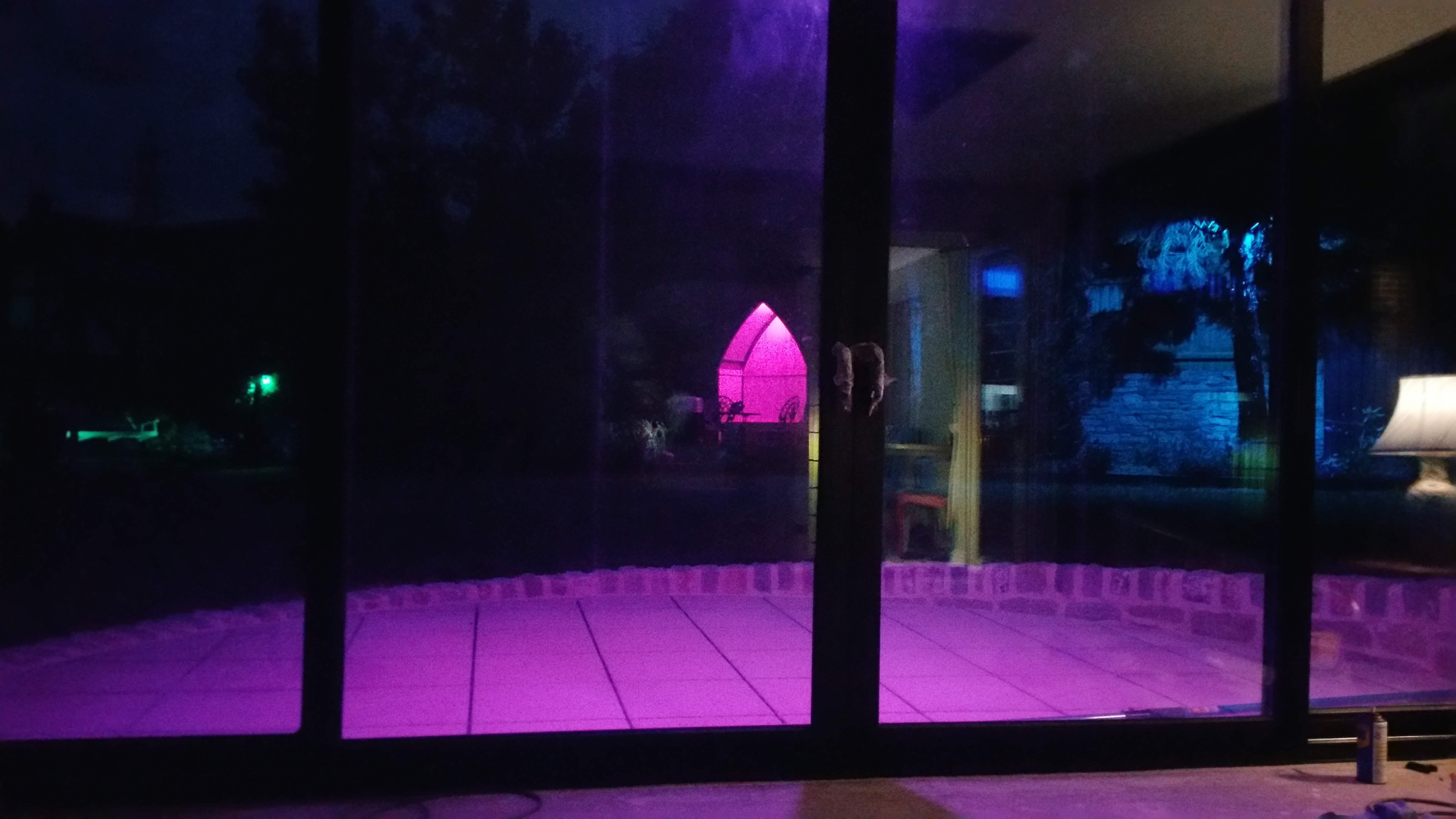
Perhaps I've got entirely the wrong mindset. I really don't know. The primary requirement is to create a comfortable indoor space with uninterrupted views of the garden (which the main house does not at all). I am under no illusion that heating this space for winter use will not be a luxury that has to be paid for - but my energy calcs indicate a cost of less than a pint at the local for a day's use by the whole family, even when freezing outside. Now I'm not a drinker so I'd be thoroughly content with the deal. As for summer heat, the end-gable wall of the house sits between the garden room and the South. In practice the old patio it's being built on was our best retreat from the 33C summer heat last year so I'm really not expecting a problem there. Only the early morning Sun gets to one side which should come in handy making it a cozy breakfast experience. The glazing consists of sliding units on all three elevations so it won't take much to get a through draft anyway. But I'm open minded about all this, and if I've got something fundamentally wrong and someone can show me why, then I'd view it like ProDave does as a seasonal retreat.
-
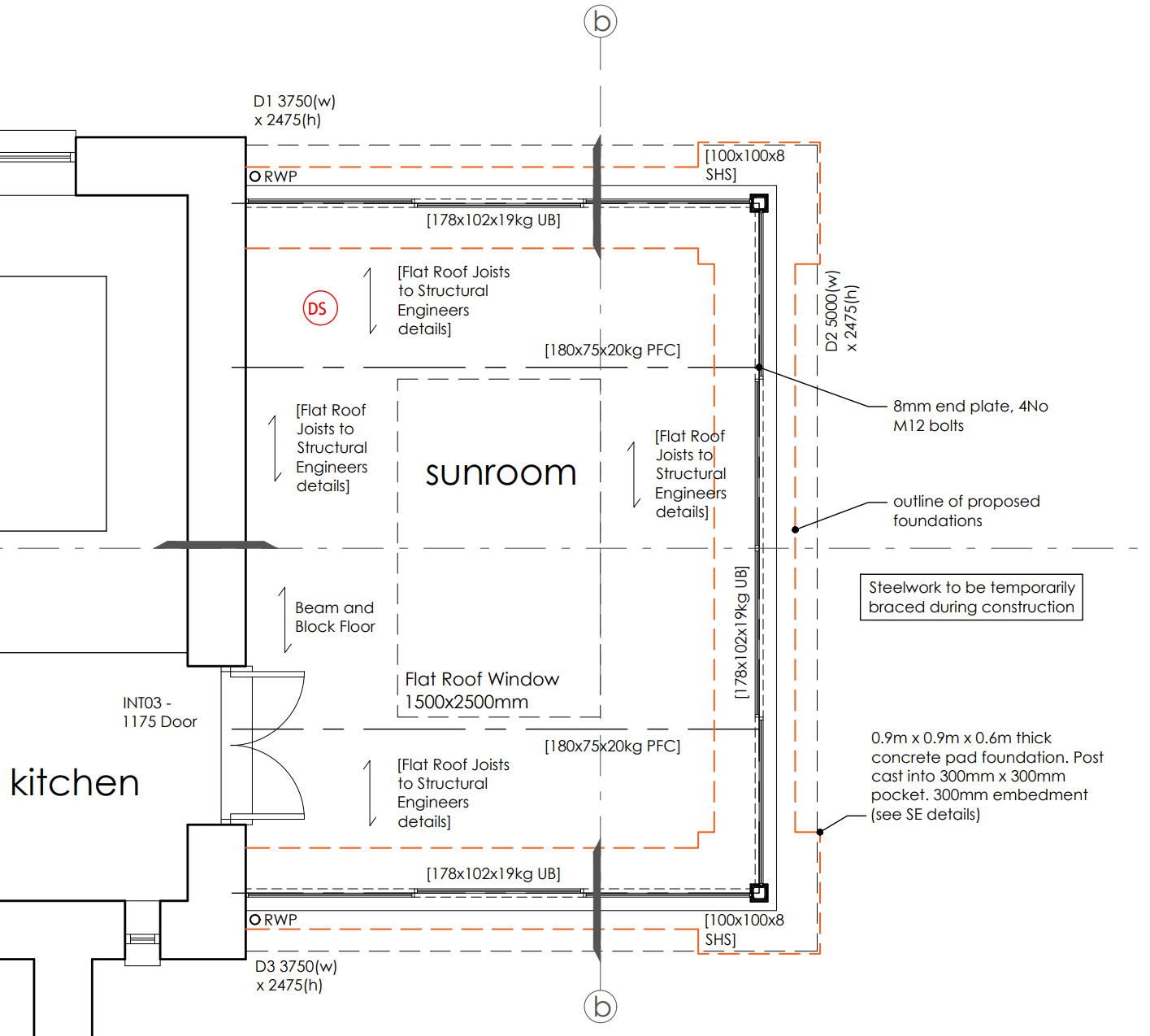
I did look into trench heating but the prices were sky-high! Yes, that's one of the drawings submitted by the Architects to BC. There was no feedback r.e. over-glazing. The glazing units are 1.3Wm2/K and there's just under 34m2 of it. 1KW for a 22C differential doesn't strike me as outrageous? This room can be closed-off with the original outside door and the heating cct isolated however there are only a handful of days where it drops below zero here on the South coast (who knows what's to come though)
-
Here's an extension we're currently building. It's laughingly called a Sunroom but it's longest wall points N.E. The whole thing is floor to ceiling double-glazed, off a beam & block floor with 100mm celotex + screed and capped with a flat warm-roof construction. This is being built as an alternative to the typical bolt-on conservatory that could only be used comfortably for part of the year. Poking the dimensions and materials into online calculators yields a consensus Heat Loss of around 1500W but I'm only only taking that as a very rough guide. The aim is to be able to wander into the room at any time of day, any day of the week. The concern is the warm-up time when we set back the temperature overnight and just how costly this might prove to be if we find it needs to stay on longer. The main reason for choosing UFH over a wall mounted rad in this case is to get heat out to the glazed sides and counter the inevitable cold-pooling of descending air in those regions. One alternative I could think of was to set a perimeter strip of under-tile electric mat in conjunction with a rad (just to offset the cold pooling) but I instinctively shy away from electric heating having already heavily invested in energy saving appliances. Any wisdom to share here?

-
Hi mvincentd, yes there's a mix of fixed and sliding units. I would have been very happy to have a CHS pole in the corner if had been offered it by the SE but this is the reason I asked about the 203 UC here as it's been the only solution on the table.
-
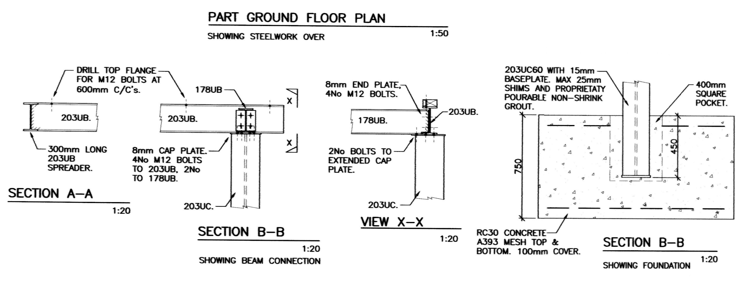
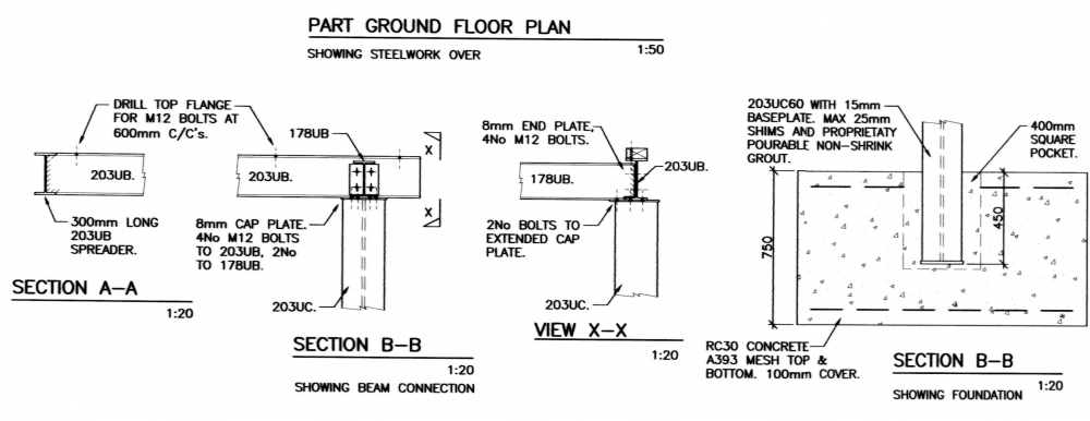
I apologise for all the confusion! I'm having difficulty digitising the drawings in my present situation but here's the sectional views accompanying the previous plan view I posted:
-
Hi @TerryE I get what you're saying here. However there's a great deal to be said for the quality of natural light that results from floor-to-ceiling glazing. This area is to be used as a day-room that will get extensive use all year round. Far better I think than a typical bolt-on conservatory. BTW, I know you from your generous contributions to NodeMCU/LUA. I've lost count of the number of ESP8266's I've embedded with that firmware into various projects over the last few years.
-
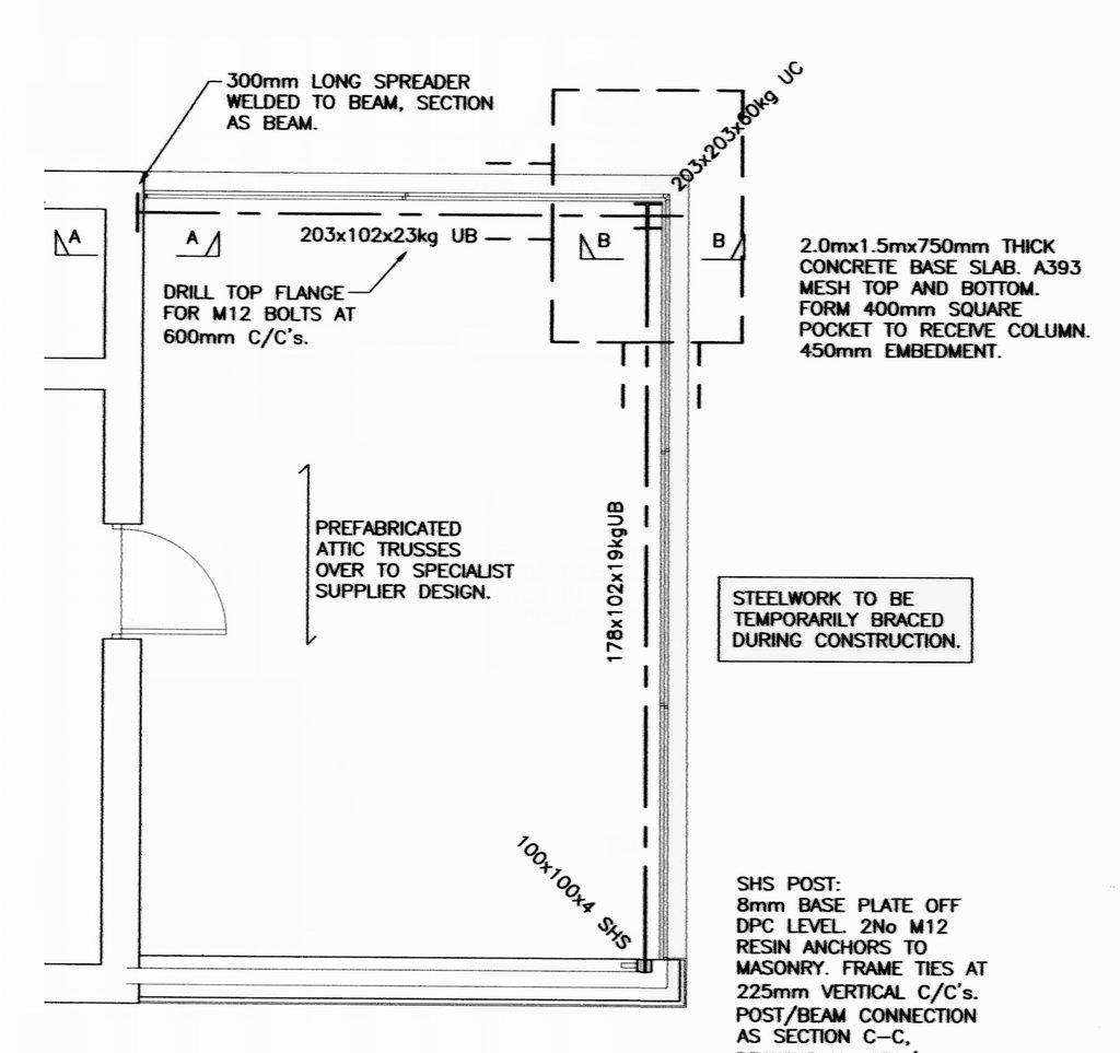
Honestly, the only wall sections are on the architects drawings and they have no detail showing how the gable is supposed to be constructed - but this is probably because the attic trusses are yet to be designed by the manufacturer. I only have large format print copies of the drawings so they're not easy to digitise. Here's my best shot at digitising the SE plan that I attempted to boil down into the simplified sketch above:

-
Having a long hard think about this. Your suggestion of creating masonry piers makes a great deal of sense.
-
Gable is entirely timber + cladding. Sorry again for the crappy drawing - the cavity wall stubs are drawn as a single block representing their footprint.
-
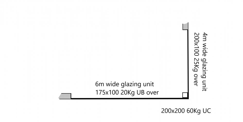
Just to be clear, above this room there is only a 'Room In Roof' formed by prefabricated attic trusses. It's a Chalet bungalow. I hadn't had any concerns about the lateral beams (up until now) but setting those aside for the moment, what do you make of the 203x203x60Kg? I only very roughly sketched the layout to show relevant parts. Cavity walls shown solid.
-
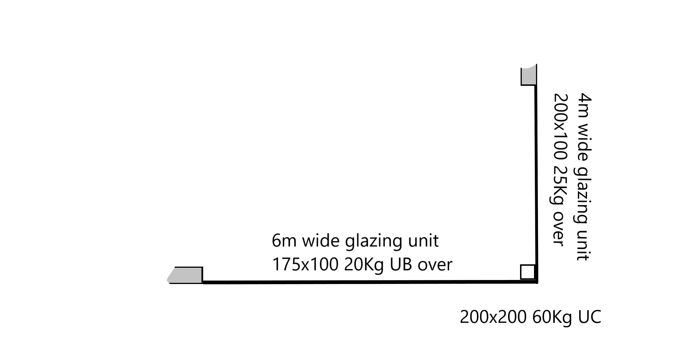
4m x 6m window spans with steels above. The 200x100 UB supports one end of the roof trusses running laterally across this highly simplified diagram: Masonry walls (not shown) support the roof trusses at the left of the diagram. That's the essence of the plan. I don't have the exact dimensions of the window frames but the architect seems to think the 200x200 can be boxed-in and decorated with next to no clearance to the glazing. Also, whatever its finish, it's right on display from the outside. Offsetting the steel from the glazing would make more sense to allow for finishing but might not suit the necessary location of the steelwork above. Also, it would still leave us with an ugly column in pole position. I'm sure this sort of application has been engineered before. Only the other day I saw a corner window without a prominent post on the TV show "Ugly House to Lovely House with George Clarke".
-
Trying to be diplomatic here. Our architect has drawn up our living room to have floor to ceiling glazing on two walls meeting at a corner. This is to make the most of a nice view. We understood that there would have to be a vertical steel of some kind to support the floor above (a room-in-roof constructed from timber attic trusses with slate cover @ 50' pitch) but the SE drawings have come back with a massive 200 x 200 I beam rammed right up to the glazing frames. That's before boxing around and finishing in the impossibly tight gap to the glass. On asking if this could be switched for a slimmer alternative, we're simply being told 'no'. Similar constructions I've seen elsewhere utilise 100mm square posts although these may have been single storey. Anyway, a wide variety of sections and wall thicknesses are available out there but the SE won't budge. He's been paid already and TBH we've only just picked this up while studying the drawings. I can't see a way out of this as hiring a different SE we may be back in the same situation only £££'s worse off. It doesn't seem to be any real fault of the architect although they might have warned us. We haven't got the engineering knowledge to call out the SE on the decision and the plans already got building approval for the giant steel. Any thoughts on how to handle this? I mentioned diplomacy at the start of this post because IME these kind of professional can get a bit cagey when their decisions are brought into question. If not done right, all flexibility can go out of the window.
-
I'm very impressed with the replies here and the depth of experience and knowledge. Thank you all. The silting of the permeable membrane mentioned by joe90 is something I've wondered about before. In our previous property the land drains became disfunctional after a few years but the increasing levels of flooding came so gradually I'm ashamed to admit we kind of ignored it. Thinking logically, any silt stopped by the membrane will accumulate there - and with clay it can be surprisingly impermeable. I've been pumping the newly poured trenches and when getting down to the last few mm, the inevitable fall on the concrete can easily be dammed by the last bit of silt which has to be brushed along to get the last drop to flow down to the pump sump. So it might make sense to let the silt freely pass into the perforated channel so long as a reasonable amount of water goes through as well. On that score I have very few doubts. I like the sound of that although Type 1 has a downside... Type 1 has higher content of 'fines' and seems to develop a 'paste' when wet so I'm a bit leary of topping the pipe with that. Type 3 has fewer 'fines' and consequently costs a fair bit more. Given the extremity of the surface water issue it could prove to be worth it.
-
Hi, first post on these forums. Our building project has got to the stage where foundation trenches have been poured and block & beams are supported on blockwork. Before we go on, the ground has proved very difficult - heavy clay on a sloping site and water frequently pools on top of the foundation and hence under the floor. Because of this we are going to lay 100mm perforated pipe all around the perimeter and discharge it into the rainwater drainage exit pipework (below foundation level). The question is what material to use for backfilling over the pipe. I know it will require something like gravel with a Geotex wrap to prevent sediment getting into the pipe but I don't like the idea of bringing any of the clay back in as it will shrink and settle like crazy. There are to be paths and patios to most walls so whatever backfill is used it has to be well compacted. Would 10mm gravel (around the pipe) topped with Type 1 be sensible or any better ideas? The depth required varies but there's a considerable volume to fill so cost is highly significant.