Jeremy Harris
-
Posts
26430 -
Joined
-
Last visited
-
Days Won
360
Everything posted by Jeremy Harris
-
We have the pumped outlet Bio Pure. It's more than a tank with a submersible pump in it. There is a separate chamber inside the tank, with a weir that takes the liquid off the top of the main treatment tank, from the outer zone where the effluent has been treated (so clear from the recirculating bubble chamber in the central "tank within a tank"). The submersible pump sits in this clear effluent chamber, with a float switch. When the clear effluent level rises to the point where the pump is triggered, it then empties the clear effluent chamber in around 20 seconds. This clear effluent chamber also has an alarm float sensor, as the pumped system comes with an alarm unit that senses both air pump pressure and the level in the pump chamber. The pump that's in the clear effluent chamber is a fairly standard stainless submersible unit, fitted with a float switch and a rigid pipe connection that connects to the outlet (50mm MDPE) via a two lever bayonet quick release. This rigid connection keeps the pump positioned in the centre of the clear effluent chamber, and the quick release makes removing the pump pretty easy.
-
Our service void battens are 50mm and I just glued and screwed 12mm spacer boards to the internal skin and fitted 45mm boxes. The boxes ended up coming about half way through the plasterboard.
-
Yes, we did mention them about 5 or 6 months ago I think. Personally I'm not convinced, I prefer metal back boxes that are securely fixed and that are spaced so they project into the plasterboard. Holding the board in place and then tapping it against the box marks where it needs to be cut.
-
Whoops................ Perhaps I shouldn't have scanned mine a day or two ago, then.
-
That same argument could be applied to most of the drives in the UK, as very few are wide enough to allow two cars to pass side by side in opposite directions. It smacks of grasping at straws to me, as I can't see anything in any planning guidance that suggests that a private access has to be wide enough to let two cars pass side by side. If he continues to object, get it in writing that the reason is that two cars can't pass side by side, then appeal. It will get through at appeal I'm sure, simply because the reason given doesn't seem to be valid.
-
The ones I used (as in the link earlier) had a stainless steel ring to "bite" into the copper, a lip seal that fits around the copper pipe and is compressed to form a seal and a rigid plastic ring that fits under the MDPE fitting compression nut to hold the whole thing together. There's no flex or movement at all, the whole things is very rigid when tightened up, as the rigid plastic ring engages in the bore of the MDPE fitting to keep thing in line..
-
Yes, it fits inside a coupler. I used 25mm MDPE, as that's about the same bore as 22mm copper, but you could just fit a short length of 28mm copper with a 28mm to 22mm reducer soldered on to get you to 22mm. I've found these fittings very secure, as the stainless steel grip ring bites hard into the copper pipe, holding it very securely in place.
-
I'm with Nick on this, as I have a couple of MDPE to 22mm connections. I used these: https://www.pipestock.com/philmac/adaptor-kits/copper-connection-kit as they just fit into an MDPE coupler or elbow and convert it to take a copper pipe on one side.
-
I've often wondered where Silverline get their steel from; must be a special mill that produces steel with all the properties of soft cheese. Has anyone, ever, got a decent tool from Silverline? I avoid them like the plague, having been caught twice, once with a bike bottom bracket tool, then again when I bought a pack of the softest, most crappy, band saw blades I've ever seen.
-
It comes down to the exact date that the contract was signed with the main contractor. I believe this was before CDM 2015 came into force. The building regulations application (which was originally going to be Full Plans, but was later changed to being under a Building Notice) is dated 4th September 2014, and CDM 2015 came into force in April 2015. As the building regs application was most probably submitted after the contract was awarded, I strongly suspect that CDM 2015 did not apply, unless its provisions were supposed to be applied retrospectively to projects that were already underway (which I don't think is the case). I think this is just another inaccuracy in that article, driven by the author's political bias.
-
It's a pity that some of the reasonably accurate detail in that article is completely overwhelmed by such a lot of left-wing political rhetoric, and some hopelessly inaccurate stuff from the Guardian thrown in for good measure. It seems that the Guardian was the source used by the author for a fair bit of the article's content, which doesn't fill me with confidence, given the inaccurate way that newspaper has reported on this tragedy. Comments regarding architects images only including white people, and all the unnecessary stuff about social problems in adjacent areas, have no place in an analysis of the cause of this fire, or the reason for its rapid spread. It seems that every time the author saw an opportunity to express his own political views he seized it with both hands, which rather undermines the credibility of the whole article. It certainly shouldn't be titled "The truth about Grenfell Tower", as it definitely isn't, even though it makes some good points.
-
 Our village is just starting up a tool share service, the sort of thing that might be very useful for one-off jobs like this. They are calling it a Virtual Tool Shed, with the Parish Council coordinating a list of tools that people are willing to lend out, and also looking after PAT testing to make sure all tools that are in the Virtual Tool Shed are safe. It's early days, but one big advantage will be that we will know what tools are available nearby. There are a lot of hobbyists and DIY'ers around, so I think we'll have a pretty wide range of tools. I know that some of my bigger tools, like the lathe, milling machines, etc, only get used a handful of times a year, and I wouldn't mind betting that there are some woodworkers around that might well have things like a thicknesser that they only use occasionally.
 -
A point I made offline to the person that had a serious pop at me, but all it did was make him more abusive........................ I wouldn't have minded, but the first electrician I used was the one that had a problem with signing off the workshop with an additional earth rod connected to the exported PE, which is why I fitted an insulated box where the SWA came up through the floor, together with another box next to it to house the termination at the top of the long earth rod that goes down through the slab and deep enough into the underlying soil to have hit the water table, I think. My original plan was just to connect the additional earth rod to the PE at the incoming side of the workshop consumer unit, but he wasn't happy with it. No idea why, but it was his name on the chit, so I just accepted it and made the workshop TT.
-
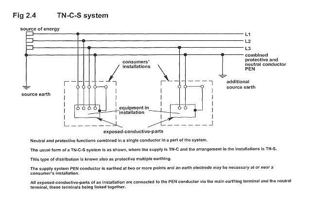
There's no logical reason to not have an additional local earth connection at the end of a long cable, it's just adding yet another multiple earth to a system that will already have several earth connections (you can see them on poles if you look around). It's also allowable in BS7671 for the "customers earth" to be connected to the PEN coming in, as shown in this figure I've just scanned in from the 17th Edition (amendment 1, so not quite the current regs, but this is still the same):
-
Yes, there was indeed a rant at me over a typo related to exactly this. I chose to keep my workshop PE separate from the incoming exported earth, which is a strict interpretation of the regs. There's nothing in the regs I'm aware of that specifically says you can't add a supplemental earth, making, as Dave says, a true PME installation. This is just an extension of the local LV distribution network topology, that has a number of intermediate earth connections along the length of the supply cables, in order to ensure that the earth impedance at the consumer end is always low. If you want to stay strictly within a defined scheme, and not cause too much angst with whoever is signing it off, then it's probably better to just consider the consumer end of the long cable as not providing a PE, and using a standard TT earthing arrangement. That will be understood well by whoever is signing things off if they get a bit pedantic. There's no good reason why you can't just do exactly as Dave suggests though, as although unusual it is safe.
-
Stuff like this that's made for the job: https://store.jdpipes.co.uk/blue-tracer-wire/
-
If you go to your nearest tool hire place they will hire you a CAT and a flexitrace, or similar. It's easy to use, just shove the sonde at the end of the flexitrace (or the one that Declan linked to that fits to drain rods - same thing) then walk over the ground with the CAT to find where the sonde is. Mark the spot with a bit of spray marker, then move the sonde in the pipe by a couple of metres and do another run with the CAT to find that location and mark it. After half an hour or so you should have a load of marks on the surface that are overhead the pipe. Join the marks and you have the location of the pipe. Edited to add: Declan and I posted at the same time, saying much the same thing
-
It's now best practice to install a trace wire alongside a plastic pipe. The wire can be connected to a signal generator and use to create a field that a CAT can detect. If laying a new long length of underground pipe it makes sense to add a trace wire, just to ease the hassle of anyone trying to find it later.
-
Shall I install mvhr
Jeremy Harris replied to jpinthehouse's topic in Mechanical Ventilation with Heat Recovery (MVHR)
Work out how much you'd save by fitting MVHR. Ours reduced the heating requirement by between 50% and 70%. If you used the lower figure, then you could quickly work out the heating bill cost reduction. For most houses an MVHR will probably pay for itself in around 5 to 8 years, I think. As above, the fresh air all year around is also a big bonus, as is the absence of noise from extractor fans. -
If you can get a flexitrace up the pipe, then you can use a CAT to find the pipe. If you can't, then you'll need to dig a few holes to try and locate it.
-
You can either export the earth down the 100m cable (might well mean increasing the cable size to get the loop impedance down) or you could just use an earth rod at the house end and have a TT installation. I'd do the latter, as you'll get a very good earth with those lakes around. It's cheaper, too, as for single phase you could run two core SWA, rather than 3 core.
-
4 core could give three phase at the house, as you may not want to export the PE down the cable, so could TT it at the house end (should be no problem getting a good earth given the lakes around). 35mm² would restrict the current to around 90A per phase, to stay within the 5% voltage drop limit, and that would be masses of power. One phase could be used to run the house (90A is more than enough - I have our main supply fused at 80A), and another phase could be used to feed the garage/workshop, if need be. If you think that the total single phase load will always be under about 90A, then you could just run a 35mm² single phase cable. In practice this would be fine at the full 100A, as although the peak voltage drop would just exceed 5% (5.5% at 100A), in practice it's very unlikely that you would ever draw 100A.
-
100m of 50mm² at 100A (absolute max per phase that's allowable by the DNO, I suspect) would give a voltage drop that's OK (3.7%). Not sure where the 70mm² came from, AFAICS 50mm² SWA looks fine, well within spec.
-
SWA is OK submerged, and yes it can be joined, using potted joints (I have a buried join where another run is tee'd off). Having said that, a new run may well be the best bet, and is what I'd do. Whether the old cable would be OK for the garage depends on its size and condition.
-
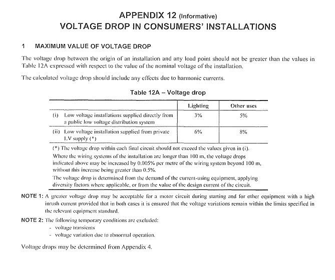
Have a look in the book with regard to cable sizing. There are two main cable sizing criteria, this one (excuse the scan - I only have a paper copy of the 17th Ed): The voltage drop limits are here in the regs: and the diversity guidance, which is non-existent in the regs (but is in additional guidance, but it doesn't really help much for a one-man workshop): There is some older guidance on diversity on the TLC website, here: https://www.tlc-direct.co.uk/Figures/Tab6.2.htm that may be useful, although it relates to the 16th Ed it is still valid, I think. I don't have a copy of the guide on this, maybe one our electricians has an up to date copy. Bear in mind that diversity calcs are often not set in stone in the regs, and the worst consequence of getting them wrong is cable under sizing and nuisance tripping - there isn't a hazard from underestimating the load, as the protective device will be sized to protect the cable, not the load. I opted to do my own diversity calcs based on how I thought I'd use the workshop, with enough of an allowance to be pretty sure that I'd rarely, if ever, get a nuisance trip. One final thing to consider is the effect on earth loop impedance if you are thinking of exporting the PE down the cable. My personal view was that I was happier with my workshop being TT'd, so I didn't export the earth down the long cable from the external CU that supplies it. I fitted a long earth rod through the workshop floor, measured it to make sure it was OK and have used that as the workshop PE. I didn't need to, as the earth loop impedance on the exported earth was within limits, but I felt happier knowing that the concrete workshop floor had a low impedance "connection" to the PE.