Jump to content

Search the Community

Showing results for tags 'the windy roost'.

  • Search By Tags

    Type tags separated by commas.
  • Search By Author

Content Type


Forums

  • BuildHub Guide: Information about the site : Introduce Yourself
    • About BuildHub.org.uk
    • Introduce Yourself
  • Build Design, Planning, Finance and Legal
    • Building Plots, Land & Renovation Properties
    • Design & Architecture
    • Funding, Finance & Tax
    • Insurance, Legal and Warranties
  • House Construction & Structural Issues
    • House Construction
    • Conversions & Extensions
    • Roofing & Lofts
    • Structural Works, Foundations & Demolition
    • Insulation & Ventilation
    • Landscaping & Outdoor Buildings
    • Damp & Infestation
  • Building Trades
    • Plumbing & Heating
    • Bricklaying, Plastering, Concrete, Blocks & Rendering
    • Joinery, Windows & Doors
    • Floors & Flooring
    • Electrics, Lighting & Home Security
    • Decorating & Tiling
    • Kitchens & Bathrooms
    • Building Materials
  • Environmental, Alternative & Green Building Methods
    • Designing Energy Efficient & Sustainable Homes
    • Renewable Home Energy Generation
    • Research & Information Sources
    • Environmental Building Politics
    • Boffin's Corner
  • Self Build & DIY: General
    • General Self Build & DIY Discussion
    • Housing Politics
    • Property TV Programmes
    • Tools & Equipment
  • Self Build Regional Groups
    • UK
    • Europe

Blogs

  • Salamander Cottage
  • The House At Mill Orchard
  • An Orkney Build (in ICF)
  • The House at the Bottom of the Garden
  • Hawthorn House
  • Rose Lane re-build
  • East Kent Self Build
  • Wee Hoose on the Croft
  • God is in the Details
  • Tennentslager
  • Kentish RenoExtension
  • Scooby Cottage renovation.
  • The Seasalter Sharp House
  • sussexlogs
  • Sips and stones may break my bones...
  • Our Journey North of the Border
  • Construction in Cornwall
  • The Fun Irish (House)
  • A house! A house! My kingdom for a house!
  • South Devon Self Build
  • Lucy Murray
  • Coffee Towers
  • caliwag
  • caliwag
  • Blackmore House
  • A woodland house
  • Druim nan Darach
  • Escarpment to the countryside
  • Recoveringbuilder
  • Netherwood lakes
  • Kingseat
  • Mr and Mrs Triassics New Home
  • Yaffles
  • Wedding Cake Re-build
  • Clancutt Lodge
  • Self-Build in Shropshire
  • South coast ICF build
  • 5 (2 adults, 3 dogs) go building in Dorset
  • Hillcroft
  • Self Build NE Scotland
  • Timber Portal Frame - but stick built
  • Self Building two in North Wiltshire
  • 1970s Chalet-style house renovation
  • Under the Chestnut Tree
  • The Larch House
  • Building in a woodland on the Isle of Wight
  • Back on the self-build waggon...
  • Gardening in the Lockdown
  • The BuildHub Gardening Blog
  • West Sussex Forever Home
  • Testing
  • Canalside Bungalow Renovation
  • Holywood Passive ICF Build
  • Finchampstead Passivhaus
  • Albaston self-build
  • Little Stud Barn
  • South East Cornwall Low Energy build
  • Scottish SIPS build
  • Gus Potter
  • Garden Escape
  • error
  • ASHP, MVHR, PV and EV combo
  • The Windy Roost
  • Wind! Yes I know but....
  • Big Bungalow Build!
  • A Rainfuel project
  • Energy Ideas
  • Rainwater Harvesting
  • Lessons from the road...
  • Dragons in the North
  • Surrey self build
  • The Old Cow Shed
  • Major extension and eco renovation in Leicestershire
  • Canski
  • Canski
  • Deep refurb and extension
  • Bog Lane Former Water Works
  • Renovation of Ellesmere Bungalow.
  • Energy
  • Hampshire self-build. Cheap, high quality and fast - we want all three
  • Da Bungalow
  • Air tightness - The cost of everything and the value of nothing.
  • Contemporary Dream

Find results in...

Find results that contain...


Date Created

  • Start

    End


Last Updated

  • Start

    End


Filter by number of...

Joined

  • Start

    End


Group


About Me


Location

  1. Wow, we have finally started, and what a journey. The goal of the last 8 days was to try to make the the stars align. We had planned several meetings / connections deliveries all to happen the 1st week in April, and this was it, lets see what unfolds. Firstly, the plot, being located high up on the East coast in the highlands, which is basically a large un-serviced field has a few logistical issues, the main one being storage, the second distance. We had quotes for containers to be purchased and delivered in the region of 4.5K so alternatives were needed. The initial solution is the back of an Asda delivery waggon, 12ft long, 7ft wide,6ft high, with 3 lockable doors, and racking for the green trays, also a larger roller shutter section. Ā£250 - with working fridge if required - (this may have a second life once were up and running with rare breed pigsšŸ™ˆ). just need to get it from Morecambe 430miles North. Secondly how to get everything to site. We bought an old removals wagon - 7.5Tonne ally box with tail lift. MOT till NOV 515,000KM - 1 careful owner Our hope was for this to get there in 1 piece, and be left on site as storage. the sum of Ā£1200. all in with insurance (which may be cancelled) its has cost us Ā£2K. Talking with my timber supplier, he warned me of impending price rises and possibility of shortages due to the unrest in the UKRAINE. so out of the blue I bought all the timber 450M of 6x2 C24, and 56 off 11mm OSB for the PODS. In addition to this I found a contact selling factory rejects of 120mm PIR insulation. In Scotland the pods need to achieve good U values, so 120mm on roof and in floors was required. Basically this guy buys pallets of insulation that are usually end of production run , or slightly damaged corners etc, and not full sheet sizes. I went to look, as he has had some bitumen coated and fibreglass coated boards. Generally the sheets are all 1200mm wide, min 600 long, most are around half board length, but will need to be trimmed to make them suitable for the warm roof. I did a deal to buy the equivalent of 44 Boards of 120mm some Bitumen coated, some fibreglass for the sum total of Ā£660. This is a massive saving on 'Box Fresh' Now I had a problem, with the insulation tightly packed into the back of the truck and leaving some pockets to slide the timber in I had filled about 2/3rd of the truck, I didn't have room for all the timber or the other stuff I was taking. The revised plan was to cross our fingers and hope the truck will not only get to Scotland , but now return with a view of making another trip. Living accommodation. We found a static caravan, 2 bedroom in V good condition, delivered to site included in the price. The deal was done and he would get the van to site for our arrival on the Thursday, along with the delivery of our other investment an old Ford 550 Backhoe Loader, with buckets and pallet forks. We decided to set off Wednesday evening, with the plan to see where we got before we were too tired, then to sleep in the Wagon / Car. The picture below was us all loaded with 430Miles ahead. Me driving 'Nessie' as Mandy has called her, and Mandy Driving the Car / and trailer. I know we look like 'Travellers' but needs must, what will the new neighbours think when we turn up..... The Journey was horrendous. Setting off at 18.00 the trip was uneventful, with he exception of filling Nessie to the tune of Ā£245 with diesel and not knowing how far these 150 litres will get us. Uneventful until we got to the A9 around Perth, then the snow started. Visibility was poor, and the local truckers seemed oblivious to it. Mandy had a big scare on a dual carriage way where she lost visibility of the edge of the road, and found herself nearly hitting the verge, a stab of the brakes and forgetting about the 16ft trailer saw said trailer try to over take her. Luckily she managed to correct this, and coming to a stop in the dark with snow on the dual carriageway, composed herself and set off again. At 03.30 on Thursday we pulled into a layby just after Inverness. Got our heads down for a couple of extremely cold hours (-4). and set off to the croft, arriving around 8.30.. During the drive we were informed the Static- our accommodation for the week was not going to make it - COVID... I managed to make a few calls and Borrowed a 3 berth Tourer from GOW Plant Hire / Groundworks in Caithness.. What a top bloke.... This is us on site day 1, digger arrived..... The Plot.. So down to it. Day 2 on site Friday. Electricity was to be connected on Wednesday 6th, we needed to dig a 30M Trench and install the cabinet / concrete base. This had to happen. Over to the digger to fire her up.... no go. Quickly the battery went flat. We moved Nessie closer, did a quick 30Mile round trip and bought some jump leads and by lunchtime and still no joy, turning over but not firing..... it was running the day before but they had to jump start as it had been sat in the yard for a few week. Ok looking at the battery it wasn't the correct one, so another 30mile round trip and the owner of a monster battery we tried again. no luck, I phoned a mate mechanic he advised trying spraying cold start into the air intake. ok another trip? , No, he told me to try deodorant as the propellant may well work, one quick spray and the old girl fired immediately. Best smelling digger in the highlands... Now to get to grip with an old backhoe, I've experience with up to 5 tonne 360 machines but never a back hoe, so this took a while to understand how to dig a straight trench next to a fence.. I managed to excavate the connection pit and around 15M of wandering trench by the end of the day. Day 3 Saturday It was cold and no amount of deodorant was working on the digger. The mighty battery was losing power... Time to try Nessie to give a boost, we got the Truck stuck in the mud... FFS. we needed the digger to move the truck, and the truck to help start the digger... This was a testing day, and I know from experience in building game you have days that just fight back, and this day was fighting hard. Mandy set off in search of some supplies and some cold start. By lunch she was back, I had made the shuttering for the cabinet base just needed the digger to get the concrete over to the hole. Cold start didn't work and we both felt deflated... Numerous attempts with planks, stone etc to free the truck were not working. As a last resort as the sun was now out and shining we gave the cold start another go and the digger jumped into life.. Obviously not a morning person... We moved the truck to relative safety of some drier ground with the aid of the digger and concreted in the cabinet. Another 10 M of trench, and we made a start exposing the water main. I noticed the digger was beginning to be sluggish and leaving hydraulic oil pools, when I check the level it was nearly empty. So Parked up the digger, next to the truck, batteries next to each other - just in case. We retired to the un heated caravan, and I went to the Generator to start it, we had a 2KW heater that helped take the chill off, A couple of pulls and the cord snappedšŸ˜‚. the day was going to round 12 like it or not. So tools out and repair underway. Day 4 Sunday. No Hydraulic oil till Monday so left the digger alone, and marked out the position of the pods, and the septic tank, I wanted to do some digging here to confirm the suspicion that the rock level was high, and some breaking out will be required. We hand dug a trial hole for the water main, as we found electricity cables running towards where the trench was going. We hit rock 300mm below ground, so were happy to dig this with the machine on Monday, We also started unloading the insulation and timber from the truck. We sandwiched timber and insulation with visqueen and ratchet straps to create a heavy mass that hopefully wont blow away whist were not there. Day 5 Monday. With Hydraulic oil on board and the shelter of the truck the digger fired first thing, and we were off. Mandy continued un loading insulation. We dug a small trench for the water (we new the main was laid in a blasted trench to a depth of 800mm) we had to breakout our trench with a 110V Breaker to obtain the 600mm depth and hand dig to expose the water main, I left Mandy to this while I dug the septic tank hole, I got to a depth of around 800mm before I hit the rock. This will need pecking out now. We installed a homemade standpipe, and blue pipe, then asked for a track inspection via the online portal. We were given date of 11/12/13April, but we put a note on to say we were on site until the 8th. They responded and the Meeting was set for Wednesday 6th - result. Day 6 Tuesday - the night was very windy and wet. A cold and wet start, We finished off the electrical trench, laid the ducting / draw cord and all was set for connection the next day. Made a start on the pods foundation dig. Day 7 Wednesday - electrical trench was full of water, and the ducting was floating. the heavy rain drains towards the sea, and thus straight into this trench, I was concerned that the Install may be called off. SSE turned up around 10.00 and were not bothered in the slightest. They connected a new length of 95mm Wavecon to the pole and jointed the existing 2 houses and our new supply - 2 core 35mm straight concentric to this 95mm cable. Resin pour joint box, and fitted the 100A cut out in the cabinet. They were done in 2 hours. left me to throw the cable in when the resin had gone off. Scottish water inspected the trench, and this has been signed off and will be added to the works list, hopefully a few weeks. I filled in the cable trench, We managed to rough dig out the pod foundations and found the rock is close to the surface. so the slab foundation will be pretty much mass fill concrete around the perimeter, with some MOT to reduce the thickness to 4" for the slab. This will then have a Radon barrier on top and a floating floor insulation on that, Due to the poor living conditions and more rain and wind we made the decision to leave Thursday morning. Day 8 Thursday, We packed up the caravan and Nessie then dragged the caravan out of the mud with the digger. The trailer was also dragged clear with the digger, but Nessie was so at home she didn't want to leave. I was pushing here through the mud, but she was sinking. Fortunately tour Farmer neighbour saw our plight and came along with his massive tractor and dragged her clear. We left site battered, bruised but happy in the knowledge that no matter what was thrown at us, we had achieved what was required and more to boot. Thanks for reading... its all possible, Mandy made a few videos if you want to see them https://www.facebook.com/The-Windy-Roost-101816829105927, you can follow the progress there as well...
  2. Thought I'd do a short blog on the Polycarbonate tunnel we built. Our big field suffered with no storage, and location meant containers were very expensive to transport. so one option was to build a polytunnel, which we have planning permission for. again due to location, 500m from the coast 73M AMSL I wanted something sturdy. so looked at off the shelf packages. in the Highlands and Islands the PolyCrub is seen as the mecca. Designed in the Shetland isles, guaranteed to withstand 100MPH winds etc etc. due to the ability to get CROFT grant assistance on these, the price is, IMHO, artificially high CIRC 6K for 4M *6M.. this wasn't going to happen, so after looking at many photos I designed my own.. Basic principle is hoops of MDPE pipe secured to posts in the ground, then 3*2 timber used as horizontal support, with Polycarbonate sheets secured to this timber. the bottom sides are then clad. My design was to use 65mm Black MDPE pipe, and secure the timber with coach bolts and penny washers through the pipe. this way I get a guaranteed fixing that won't pull out , and it still allows for flex in the whole structure. 4m wide x 6M long, but this can be extended. My ground has bed rock close to the surface, 300-500mm below ground, so just knocking in post wasn't going to be secure enough to withstand the winds, also where I was sighting the tunnel its on sloping ground, so I couldn't get it level. I cleared the area to removed the top vegetation and a bit of the top soil. and dug 14 holes. then due to rock levels I then core drilled the rock to allow for the post to be deeper. We then set these in concrete, (at the same time as doing the slabs for the cabins.) The next day we had a look and I wasn't too happy with the security of the posts, so slight change of plan, we created a plinth. basically I used some 6x2 either side of the posts, with a slight angle, then filled this with concrete (again we used ready mix at the same time as back filling the treatment plant) this added about 300kg of concrete to each side, and joined all the posts together, and gave us a solid plinth at the side. No Photos of the next stage but we cut 7M lengths of 63mm pipe, this when placed over the posts gives approx. 500mm dwarf walls and a 6M polycarbonate sheet, giving a head height of around 2.3M. we used a plumb bob to get the centre line on each hoop and drilled an 8mm hole through the pipe and secured the top 3x2 treated timber to al the hoops. One thing we found was that the MDPE did not bend uniformly, this may have been due to slight errors with the posts being plumb. The resultant timber (which was not very straight), snaked from hoop to hoop. after head scratching and re thinking. I decided it was a poly tunnel and to get on with it. we used 7 lengths of timber jointed with half lap joints to extend the length to 6.5M. if using a clock analogy the timber was placed at 9,10,11,12,1,2,3 positions, with the 9 & 3 o'clock being 500mm off the ground, also ensuring the 9 & 3 o'clock timbers were approx. 5.8M apart circumferentially. Then it was a case of securing the polycarbonate sheets to the timber. each sheet is joined with some soffit H joint strip. (you can buy a clear joining strip for the sheets but for a 6M length it was around Ā£65. the H strips proved extremely difficult to connect the two sheets together, or should I say impossible. so I cut off the back edge on one side and used some glazing sealant. this way we could attach the strip to the polycarbonate prior to bending over the tunnel. and each sheet 'H' strip basically lapped over the previously installed sheet. day 2 we had the basic structure. It was noticeable that the curve was not symmetrical, so putting the door frame header in by securing to timbers at 11 and 1 o'clock was not level. I overcome this by using a ratchet strap attached to the 11, and 3 o'clock timbers and tightening until timbers at 11&1 o'clock were level. I then put the two door jambs in (concreted at the base) and cut to the length required and secured to the header. This worked and the tunnel was now more cylindrical. I framed the rear by baring 3x2's off the horizontal timbers. Last steps were to clad the base, I used 4*1 treated timbers that were screwed into the MDPE pipe and wooden posts. then used strips of visqueen to create a more sealed dwarf wall, this will help prevent driven rain from the winds getting inside. over this I used Larch timber backs* to create a vertical cladding All in with hardware, polycarbonate, timber, concrete the project cost Ā£1200. not cheap, but its solid as a rock. It withstood the first Autumnal storms this week with winds hitting 50MPH. Its also very warm inside, even now as the temperature is falling. Larch timber backs are the offcuts from the saw mills and are reasonably priced as scrap. we purchased a pack of timber backs, approx.40 lengths of larch timber with bark in 4.8M lengths for Ā£100. these are not uniform and taper etc, but as i only needed 500mm lengths it was straight forward to make it work.
  3. Had anybody had a steel building in my case 47 ft x 30 ft x 14 ft built and have the erection costs to hand? It will be 4 portal frames, timber perlins and metal clad. I've got package costs and kit costs and it seems like most things the sum of the parts have a big profit margin attached. So I'm looking to guage just erection costs if anyone has some?
  4. My initial plans were to have rainwater harvesting, build hub taught me no.. so with that scrapped I needed an alternative, soakaways are difficult due to bed rock levels. In addition to this we have lots of run off on the croft, and the track to the house floods. We have already installed a pond for the ducks and this has a large berm to the back and sides so that the runoff is held back and slowly soaks away, but this winter has proved it overflows regularly, that's around 3000L extra. So the plan was to install an overflow pipe from this pond to a new larger pond. The larger pond also acting as rainwater run off capture. The larger pond will have 2 levels, a pond and then an extra layer to act as a overflow that can evaporate and or be pumped to the rubble drain in drier times. I got a big carried away with the backhoe and ended up with around 10M x 8M and over a meter deep. The overflow capacity will be around 30k - 35k L. We had to peck out some of the rock to get depth, and at the front used "as dug" rock from the quarry to form a rough and rugged stone wall, quite in keeping in Caithness. Time will heal the scars and soften the edges with planting. Due to the two levels we came up with the idea of hiding the liner under some camo net, that we intend to plant up in time. Not sure how this will stand the test of time. From the house the rainwater enters a rock filter, an idea loosely based on a post from @ToughButterCup- thanks. From the rock filter we have created a little stream that the rainwater will flow down and into the pond. In addition to this we have a pump that will take the water via a home made skimmer from the pond and filter the water from the pond through the rock filter and stream constantly. This also has a diverter to pump the water past the house and into the field to reduce the overflow capacity in drier times. This is the rock filter, and some of the pipework yet to be buried. Getting to this stage ticked a box for building control as we now handle our run off. We got our completion certificate on the house this week, yeah. There are some things to finish, the second bedroom needs decorating and trim work. And a few small jobs here and there, but in general the house is decorated, and fully functioning. We started the build in earnest around May 23 I think, so quite pleased with the effort and timescale we achieved. It's was built by me and Mandy with the odd person helping with concrete pours. 3 months in summer were busy with the cabin rentals that saw Mandy spend 3-4 hrs a day turning them around for the endless NC500 travellers.šŸ˜ We're embarking on the VAT reclaim soon. To summarise the build: 89sqm True bungalow Floor 0.094U (300mm EPs 120mm concrete) Walls 0.139U ICF with 50mm EWI and 25mm PIR IWI Cold roof 0.1U 25MM PIR 400MM mineral wool. UPVC triple glazed windows and composite doors MVHR, 4kW PV in roof, 5kW ASHP, UFH. EPC A103, Airtightness 0.83 ACH.
  5. HiMy initial plans were to have rainwater harvesting, build hub taught me no.. so with that scrapped I needed an alternative, soakaways are difficult due to bed rock levels. In addition to this we have lots of run off on the croft, and the track to the house floods. We have already installed a pond for the ducks and this has a large berm to the back and sides so that the runoff is held back and slowly soaks away, but this winter has proved it overflows regularly, that's around 3000L extra. So the plan was to install an overflow pipe from this pond to a new larger pond. The larger pond also acting as rainwater run off capture. The larger pond will have 2 levels, a pond and then an extra layer to act as a overflow that can evaporate and or be pumped to the rubble drain in drier times. I got a big carried away with the backhoe and ended up with around 10M x 8M and over a meter deep. The overflow capacity will be around 30k - 35k L. We had to peck out some of the rock to get depth, and at the front used "as dug" rock from the quarry to form a rough and rugged stone wall, quite in keeping in Caithness. Time will heal the scars and soften the edges with planting. Due to the two levels we came up with the idea of hiding the liner under some camo net, that we intend to plant up in time. Not sure how this will stand the test of time. From the house the rainwater enters a rock filter, an idea loosely based on a post from @ToughButterCup- thanks. From the rock filter we have created a little stream that the rainwater will flow down and into the pond. In addition to this we have a pump that will take the water via a home made skimmer from the pond and filter the water from the pond through the rock filter and stream constantly. This also has a diverter to pump the water past the house and into the field to reduce the overflow capacity in drier times. This is the rock filter, and some of the pipework yet to be buried. Getting to this stage ticked a box for building control as we now handle our run off. We got our completion certificate on the house this week, yeah. There are some things to finish, the second bedroom needs decorating and trim work. And a few small jobs here and there, but in general the house is decorated, and fully functioning. We started the build in earnest around May 23 I think, so quite pleased with the effort and timescale we achieved. It's was built by me and Mandy with the odd person helping with concrete pours. 3 months in summer were busy with the cabin rentals that saw Mandy spend 3-4 hrs a day turning them around for the endless NC500 travellers.šŸ˜ We're embarking on the VAT reclaim soon. To summarise the build: 89sqm True bungalow Floor 0.094U (300mm EPs 120mm concrete) Walls 0.139U ICF with 50mm EWI and 25mm PIR IWI Cold roof 0.1U 25MM PIR 400MM mineral wool. UPVC triple glazed windows and composite doors MVHR, 4kW PV in roof, 5kW ASHP, UFH. EPC A103, Airtightness 0.83 ACH.
  6. All the reading of posts on here at the design stage and the hard work implementing the experience of others on your own self build can be summed up / justified with just 1 image. Even when building on a very tight budget. This is my energy usage @ The Windy Roost since we got here. Upto January 24 we were in the static, we were never really warm used Air to Air heatpump for heating, hot water and cooking was LPG. We also had around 4 summer months of our cabins being used, again electricity for heating and cooking, DHW is LPG. The blue line makes me feel warm and fuzzy inside. That's our electricity for the self build, a whole house fully electric and blissfully warm with ample DHW. (With some limited cabin usage). To all self builders going through this, it's worth the effortšŸ‘.
  7. Around 11 months ago, we started from a stripped site, the treatment plant was in and running the cabins / static so drainage just required connecting up. we had to wait for the warrant to be amended (change to the certificate of deign) this held us back ma month or so until the BCO just said "get on with it, we can sort that later"- top guy!! If we had waited for the amended certificate of design we would still be building, it took him 5 months to get it to us. I've documented most of the build in blogs on here, partly to have a refence to remember the process, partly as pay back to Buildhub for the inspiration and pointers in the planning / design stage. I'm so glad I spent hours looking at and reading others blogs that we made the switch to ICF. I'm convinced there is no way I would have achieved the efficiency I have for the money spent. Budget was always tight, so some decisions have been made due to Hobson's choice, leading to triple glazed UPVC windows and composite doors. The front door, south facing GRP Composite with low threshold and a slim glass panel leaks with 40mph winds, this leaks through the gazing cassette, and the low threshold. as I know we wont use this door much, we went for a slam lock, another mistake, it blows a gale through. To be fair the company are re making, I'm just not sure if there re-making the panel or the full door, I did ask, if they were remaking the full door to change to standard handle and lock, so it can be adjusted to minimise the drafts. we will see what happens, a full door replacement will mean taking off the reveals in side so a complete PITA, but worth it for no drafts. We had the airtightness test carried out, and they used the front door for the blower door to mitigate any issues with that door. I had put caps in the MVHR. so he just cracked on, the back door is not perfect again due to the low threshold. He didn't seal the blower door to the frame, not sure what the procedure is but seemed a little frustrating. We achieved 0.88 Air permeability, which I'm very happy with, budget wise we didn't spend hundreds on airtightness tape, just designed good solutions, and the doors leak a bit . Our As built EPC came back at A103 , with a possibility of A128.. the report say A105 if we install Thermal Solar EST saving of Ā£40 pa , and A128 with a wind turbine EST saving of Ā£1100 pa, so pretty much the best we could hit. To finish we need to sort out some paths outside, ramp, and the rain water pond, but other than the second bedroom need decorating the house is done. Next week we will hopefully get building control around to see what he 'needs' to get a completion cert. I'm hoping for some flexibility on the ramp and pond, . We need the VAT refund to pay for this stuff. We are working our way through the invoices, but we built for less the 90K and we still need the VAT refund. I've enjoyed it all, and we both agree we have a home. Good luck to all of you with your current builds.
  8. Just a very short blog to show the windy roost ( not fully finished, is a self build ever?) plant room. I'm quite chuffed I got it all to fit, and I think it's quite neat. It's full DIY and house's the UVC and combined buffer, UFH manifold, MVHR unit, inverter, consumer unit, network hub. All in 4MĀ³. Plus storage to come. Yes, the printer doesn't fit, but it's coming to its end of life so that's all it's getting for now. Jobs to do: Ceiling Insulate MVHR ducting / box in Shelves on the left hand side Clothes Airer ( a Scottish requirement to have one)
  9. HI all. Would anyone with some knowledge like to give me an opinion on the AHP60 ASHP. Spec attached. its in conjunction with my other post, so run this to heat a 300L UVC for 2 camping pods. the money is good, brand new 3 year warranty. It is cheaper than the Dream units on ebay. and at this cost is sort of a no brainer unless someone see's a big issue. I've taken into account that parts if not local will take an age from China, but the immersions (on the tank) will be my back up. Might be convinced to buy 2 and use for the house as well... AHP60Spec.pdf
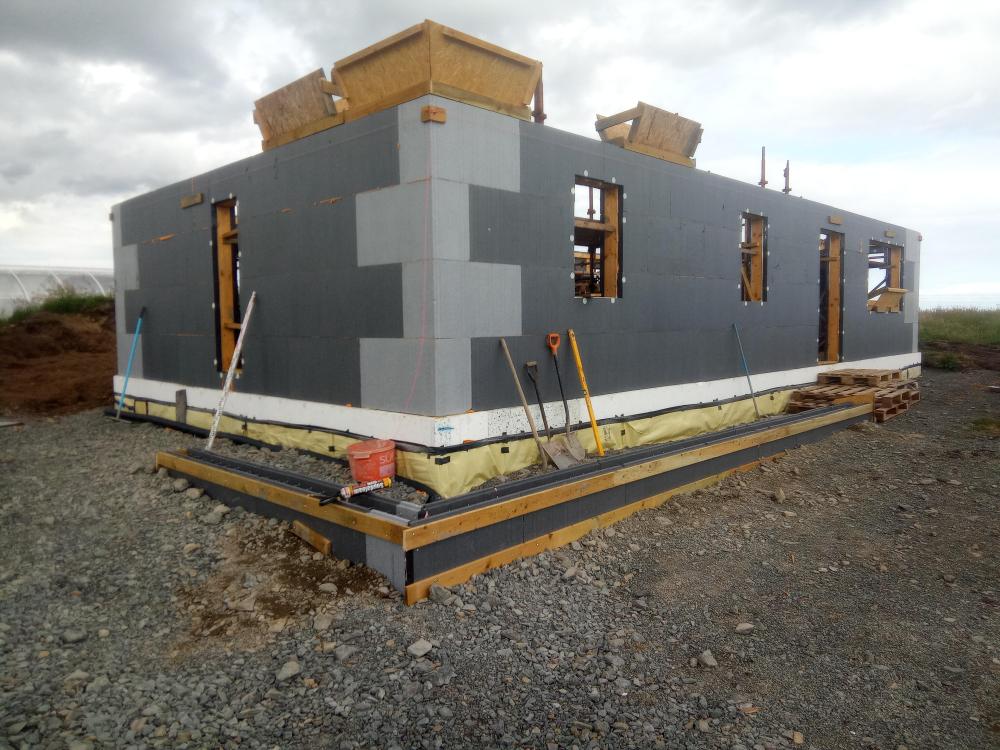
  10. It's been a while since my last blog, but we've not stopped, the days are shorter and the weather skipped autumnšŸ‚ and dived into winter with a few storms and loads of rain. Our windows are budget friendly triple glazed UPVC, and composite doors. The external EPS was sealed at the cill with EPDM airtight tape, the tape has reinforcement in it and can be moulded, it does crease but creates a water tight junction and sticks like the proverbial to the EPS. We created a cheek reveal with an additional layer of 50mm EPS and sealed the upvc frames against this, I then ran a bead of sealant against the face and edge of the EPS giving two seals. Then when clad a third seal. I used soudal air tight foam and I thinks it's LMA sealant, soudal's airtight solution. The winds gave good opportunity to test for air leaks when had several days of 35mph winds. This proved a good test with a smoke pen. The internal frame was sealed with soudal sf40 which adheres very well to the upvc and timber blocking, when cured it is like rubber. The cladding is larch boards in 2 widths 150mm for the bottom layer and 100mm for the top. We finished the top of the windows with a custom palistol coated drip The bottom of the EPS footing was finished with reclaimed slate. Inside we are having a cold roof. We needed to add 25mm pir under the truss cord to satisfy the tightened regulations in Scotland. We tapped the foil boards with foil tape, and the perimeter boards were pushed to touch the wall plate. Then used airtight foam between the PIR and internal IFC wall creating a seal. Under the PIR I used plastic membrane that I spray glued to the PIR, and this draped down the perimeter walls. The under ceiling was battened and counter battened, this created a service void for the cables and not penetrating the loft. The plastic was jointed with EPDM airtight tape on joins and walls. Cables were put inside Flexi conduit that was cut into grooves in the ICF. (All water pipes were run under the slab.) This picture shows the detail for the airtightness and the service void. MVHR ducts (7 plenums ) were run in the loft, and under 400mm of loft roll. The manifolds are also under the loft insulation. I made these airtight using the same EPDM tape. I made gaskets out of the plastic with a circle cutter and stretched it over the plenums, then air tight tape to seal everything to the plastic/ PIR. The walls also needed some IWI to meet the tighter regs, so decided to go with 25mm PIR. This also added another seal for the plastic airtight layer and walls. The poly steel ICF has these metal plates at 150mm ctrs that allow the cladding battens to be secured externally and the plasterboard internally, we used self tapping drywall screws and insulation discs to hold the PIR in place before installing the plasterboard. Picture for detail below. At this stage we've got a large airtight box. Now it's a case of installing the stud work. I lined the plant room with pre painted 12mm OSB, and the bathroom with 18mm OSB ( a Scottish building regs requirement needing the ability for future hand rails etc) Electrics are simple, a few Ethernet points and sockets and spotlights. One pendant over the dining( and if I get my way, and budget allows pool table). The only penetrations from the loft are a light, PV cables, TV aerial, and 4g antenna cables. These are in conduit and sealed both ends. All other cables run in the ceiling void or stud work. I've put a few sensors in the studwork for future Arduino projects to accompany the in slab sensors. The plant room is compact, and work in progress. The PV is up and running and to date produced just shy of 300KwH in 5 winter weeks With the first fix complete it was time to plasterboard, we got 80 boards delivered Wednesday midday, just as storm Babet hit, it was too windy to bring them in, I tried, I failed so it had to stay outside šŸ˜­, covered in plastic, tarpaulins, scaffold boards and the obligatory ratchet straps. 3 days of constant 35mph gusting 50mph gave opportunities to check for airtightness. I managed to install the flush shower tray during this downtime. Once the storm blew though we got the boards inside and cracked on, the open plan lounge, diner, kitchen was boarded first and as soon as it was complete I skimmed the ceiling, 11 boards was too big for me and my tennis elbow, that coupled with not plastering anything for several years. I split the room in two and used several layers of scrim tape to plaster up to, then remove the scrim tape and skim the 2nd part. It worked well, and it's painted and the join is seamless. The next few days we mixed it up skimming in the morning and boarding in the afternoon for the next day. Today is day 182 of the build, this is basically from the cleared site that was down to rock with the pecking already done. Currently the house is fully skimmed, most of the ceilings have been primed and painted white and we started the kitchen install today. All the bathroom is here waiting to be installed, and some appliances are here most arriving this week. This has been pretty much 7 days a week, with only around 12 to 18 days off to earn some money and pay off some labour debts. We're hoping to move in, in 2 weeks with a working bathroom and kitchen šŸ¤ž, the static has now reverted to ice box during the nightšŸ„
  11. Day 31 of the build. (this is taken from the day we started shuttering the foundations) The weather up North has been spectacular for about 3 weeks, so we (Mandy and I) pushed to prepare and pour the slab before the weather changed, as I'm sure we will get a few weeks of low pressure, wet changeable weather after this spell. Following on from the foundation ICF walls, I'd already loaded around 20ton of 40mm to dust in a pile the slab area. Sat on the sand blinded radon barrier. Job one was to sort the drainage. I'd posted previously about my plan, and some constructive comments suggested changing my planned route, but with the extra length of run to the drain invert level I would have had to increase the floor height even more. So stuck with my original sketch. We ran string lines to mark the main areas, namely WC, SVP in the plant room, shower, WC and Bath, a need ran the drainage to the locations, as the utility backs onto the plant room I didn't add a drain in here as I'll run through the stud and use the SVP. Once the drainage was in place and is tested. We spread out the hardcore and compacted it. I used 10mm crush and run to bed the drainage and cover the pipes, I also ran ducting at this level, bringing in water, power, treatment plant feed plus some future ducts. To get the hardcore level / flat I used 3m lengths of galvanised conduit set on mortar pads all level to each other and used a 4M ally beam to screed the slab. I compacted the first layer then used another screed pass to fill in any deviations and used this as the level for insulation. I used a combination of 200 mm EPS 70 (50mm sheets and 100mm sheets all layed to stagger the joints, and used foam to seal to the ICF. The top layer was 100mm EPS150 this gives a firm hold for the UFH staples, and a firmer feel to the insulation layer. We plan to use a large shower tray and have this level with the floor, so I made this area sunken with two layers of EPS150 and a layer of 50mm PIR. As we were installing the insulation I installed 2 * 100mm ducts for the ASHP in the second layer of insulation these were only 800mm long, and a duct for cables. I also added flex ducts in the insulation for Hot & Cold services to the kitchen, utility, WC,Shower,bath, all these were cut using a hot knife. Lastly I cut some pipe for floor sensors in the kitchen, lounge, bedrooms and bathroom. The underfloor heating consists of three loops around 95M length, planned using Loop cad. The manifold was plumbed , filled and a pressure gauge to ensure no leaks. We have good water pressure so could pressurise to 6 Bar. ( With the heat ā˜€ļø this rose to 9 bar one day). The above picture also shows K Steel screed rails. I used these to break the slab into smaller bays, and mainly will be under stud walls. The slab will for the foreseeable future be our finished floor, so I wanted to introduce expansion joints and force any cracking to these locationsšŸ¤ž. I also used Tibmix metallic dry shake topper on the concrete, the dry shake should help suppress the fibres and also increase the surface hardness. The pour happend on Friday 16th June, the first 5cube arriving at 8.30. we did the kitchen bay first which needed the 7t 360 to move / place the concrete, then, poured the WC / plant room and utility bay. This was an error, I wanted to pour the lounge next so both bays could be finished at the same time, but under the pressure of the pour took advice to do the awkward section next. This resulted in only a 3rd of the lounge bay having concrete, so this was spread out lower so the next load could fill the bay. By the time the second load arrived, the kitchen and utility bay was ready for power floating. The pan worked well and I had some time to start edging the slab, the rebar didn't allow the power float to get to the edge of the slab. By 13.00 all bays were in and leveled, but not floated, but the sun was very hot, and the kitchen bays was getting hard rapidly, I managed to float this but was struggling to to get a perfect finish. To dry shake makes the surface hard and this was apparent, the lounge and bedroom bays floated better, and to the main the dry shake suppressed a lot of the fibres but there are still some visible. The kitchen bay was rock hard by the time I managed to float again, and although it is fairly flat you can see, but not feel, the path of the power float. I used Setseal 6 as an acrylic sealer, which seals the surface and aids the curing process. By the time we finished the floor was rock hard, I mean hard, the idea being that the slab will slowly cure now but will not be affected by rain etc. Time will tell. Due to the temp, and the float not getting to the edge, I will have to carry out some remedial work on the edges of the slab, as by the time I go to troweling these it was too late. Today the slab looks great, it's flat and level, but the perimeter 2 inch will need some polishing, as will a section in the plant room. I'm confident I can get this fixed. Time will tell. The following picture doesn't do the slab surface any justice. It looks rough, but it's glass smooth. So 10.5 cube of fibre reinforced concrete. Power Floated, and this was non stop until 17.30. My chest and fore arms are wrecked from trying to tame the power float. I'm a little disappointed in the edge finish, but looking at it another way, it's way better than if it would have started raining, or the wind that we have today. I'm sure a few hours with a wet diamond polisher will rectify the edges. Maybe another hand would have been good. šŸ¤”. Onwards to the ICF walls... .
  12. Jenki

    Topping out

    Sunday in the Highlands, and the weather has a feel of changing, we've been so fortunate on the build so far, day 105 today, but the last week or so has been wet, windy, sunny, overcast usually everyday. So autumn is on the way. July and August have been busy with the 2 cabins with around 100 nights occupied, that's over 250 people staying, and 30 +dogs šŸ˜‚. The upshot being we can afford to eat, but the labour for the build has been affected with Mandy continually cleaning and washing. We've got a roof. Again the labour for all this is me and Mandy. The ICF allows the wall plates to be bolted to the core. Getting the trusses, 44kg, onto the roof was going to be by using a borrowed small loadall. We used this to take them off the truck and set them next to the house, but lifting them onto the walls was proving tricky with access and wind. So we resorted to leaning two lengths of 4x2 against the gable end , leaning 1 truss at a time against it and then sliding the truss up the 4x2 onto the wall plates. Then dragging them into place. We had a scaffold erected at 1 end of the house and used this to raise the first truss. Then it was repeat the process. Untill it was done. At either end of the house we used an additional truss to form a timber gable wall, this saved money on the ICF as we are having a cold loft. I drew the gable frame on CAD and created a cut list, then framed the gable out of 8x2 Insitu. I used 4x2 as a sub fascia to support the eaves trays, allowing the use of capit fascia boards keeping a keen eye on the budgetšŸ™ˆ I held off boarding as I had some labour debts to repay to the local farmer, and the wind was up and down. Once we had a clear window The roof and gables were boarded with OSB. At this time I also fitted membrane and battened / counter battened the gables. Black fascia boards, over fascia vents and eaves support trays were installed. The Highland vernacular is for small soffits / no soffit. So working back from the board on board cladding thickness and the battens I should end up with just the return on the fascia showing, about 30mm. I used some 4x1 as the sub soffit that will also act as a fire stop / smoke from entering the loft. Our location, and elevation suggests we can't use enough fixings for the tiles, we opted for Marley Edgemere thin leading edge tiles in anthracite. These were fixed at the eaves, every tile nailed and every tile clipped, more on this with the GSE trays. (Mandy back to real workšŸ¤£) I also taped the joints of the membrane with tyvek membrane double sided tape. We tiled the North elevation first as this was straightforward with only two roof vents (for MVHR) These were klober 25000mm2 universal vents as the Edgemere vents only ventilated to 10,000mm2. These are a good vent but it's a struggle with thin leading edge tiles to get them to sit flat. I ended up grinding a little of the back of the adjacent tiles and drilling an additional hole and nail to get them to sit as best as I could. There is a slight kick where the rubber flashing sits under the adjacent tiles but this doesn't affect the rows above, so decided I have to live with it. (Picture from a distance to stop you zooming the ventsšŸ˜‚) The south elevation has 10 longi 405w PV panels, so I was using the GSE trays. Incidentally these trays and flashing were 50% more than the panelsšŸ˜”. GSE panels...... The instructions are very in-depth, but to be fair I just struggled with them. They suggest you don't need flashing for the top course as the tiles can sit over the trays, I doubt this works for any flat tiles / slates. Possible for pantiles if your lucky. A few on here @Dave Jones, and @dpmiller (I think) suggested this was the case, and I confirm you need the flashing kit, or use Flexi flashing, but IMO the detailing of the raised sections of the trays ( between panels) would be tricky and ugly. The thin leading edge tiles also caused slight kicking issues on the side flashing as well. So I had to be creative. (maybe this is standard for a proper roofer?) For the bottom flashing I used a 4x1 and timber wedges and used a replacement self adhesive flashing. Annoyingly the width of the trays with the raised section etc and the side flashings made the overall width 6.2M wide, so I had to order another length, and this was held up with Evri for 10daysšŸ„². Fitting the extra battens for the clamps and tray support was painful for my brain, just too much timber. I ended up fitting a row of half trays at a time. Once the trays were fitted we tiled the RH side of the roof upto the GSE tray lateral flashing. This is where I needed to think out of the box, the tiles on there own kicked up into the air a looked terrible. I also had narrow tiles (120mm) cuts to allow for the half bond. These tiles needed the nib on the back of the tile grinding off which in turn meant they had nothing to hang on, and couldn't be nailed as they were on the flashing. So I used a hanging valley clip. To get these to sit flush I had to grind a little slot into the tile face, then to stop the tiles tipping into the flashing, and to give them a second fixing, I ground a groove in the rear of the tile, then once the next row was installed used a c clip to hold it all in place. Picture shows the valley clip and wire to hang the tile. Groove for C clip. C clip in place. This was repeated on all rows, so all tiles have at least two fixings. (Overkill?) The top flashing as I mentioned, had to be ordered and the corner flashings need modifying to ensure they sit flush over the PV panel. I installed two panels, then test fitted the flashing and corner flashing, which needed snipping with tin snips, then the overlapping cut edges pop riveted to reduce the height. This was sealed with lead mate. Once I fitted the flashings, I tiled the remaining roof and top rows. The flashing kit is expensive, but works and looks neat from the ground. Dry ridge installed,l and end caps finishing the roof. Then the panels, these were simple with 8 clamps per panel. Just the gutters to fit and scaffolding can come down. Some more EWI to fit then onto the windows and doors which are sat patiently waiting for us to pull our fingers out.
  13. With the great weather in the last two weeks, following on from the slab pour, we will endeavour to pour the walls of the house tomorrow. I'm thinking I won't sleep tonight. Mentally listing all the things I wanted to do, and re ticking them off. First 7 cube is arriving at 8.30. šŸ¤ž I'll leave this picture with you....
  14. Looking at one of these, haggling on price with City Plumbing and there 15% off using there APP. Anyone any experience with them? they do a Coastal protection option which has some appeal for me being 500m from the sea. They offer a control pack but at Ā£500 I'm looking for alternatives. The house is 88sq M with UFH well insulated ICF. and a 200L heat pump tank. so happy with the size etc, Anybody know If I can just use a standard controller on this unit?. I would speak to Samsung, but I'm sure there will be a lot of pressure to use their kit even if not essential.
  15. A short blog to show my Mini spilt Air2Air install, in the Windy Roost Static. I looked at installing a wood burning stove, but we have zero trees on site, so when I looked at the costs of twin wall flue, terminals, flashing, creating a heat shield and making the caravan tidy plus the hassle of getting wood / coal, the costs were adding up. A quick question on here - Build hub, some options were suggested and I decided to go with the a cheap Air 2 Air heat pump from Appliances direct. The unit is a Telefunken 12K BTU split unit. cost around Ā£375 but did not included the pipe to connect from indoor to outdoor unit. I got 5M twin insulated copper pipe with the flair nuts from ebay for Ā£56. Our Static has a gas fire - useless, and a chimney breast made from chipboard, the side panel just screws off to access the flue. This was the perfect place for the indoor unit, as it would be a neat install and the rear will allow for the pipes to be hidden, also I could use the hole in the floor to route the pipes/ drain and power for the remote unit. I removed the light fitting, screwed the bracket on the timber, and drilled a 80mm hole, for the pipes / drain and power. Then its a case of posting all the pipes/ drain and power cables through the hole, really straight forward, the indoor unit then just clips into place. The indoor unit comes pre wired with a 13A plug top, and you need to run a 3core and earth cable from the indoor unit to the outdoor unit. this is Live, Neutral and a control / switch cable. Next to the chimney is a double plug socket, so I wasn't messing around running new cables, I just drilled an 8mm hole in the side of the chimney breast and used 2M extension lead to plug the unit in. I used some zip ties to secure the extension lead and plug to the pipes (these were put on after the photo below). and that was the internal work complete. zero mess, and no rework / decoration required. The outdoor unit was going to sit directly outside, behind the chimney breast, the ground outside was not level but it is bedrock, so a made a simple frame and made level concrete pad, and cast some hook bolts into the concrete. For initial research I spoke with a Local (ish) refrigeration engineer, and he said he would connect for Ā£120. but was telling me there is nothing to it, and if I was doing everything else then maybe I do it all??? I found an American You tube guide which was helpful on the pipework side. (linked below) Basically, the unit comes pre charged with gas, so you are not filling with gas etc. the main issue is removing the air from the two pipes you install. This is done with a vacuum pump. (some more expensive units come with pipes and they are pre-vacuumed with quick connectors) I found a vacuum pump and gauge set for sale on Vevor for Ā£79 so Ā£41 cheaper than the refrigeration engineer. I bought one, and an adaptor. I'm not suggesting anyone does this without an F - Gas Engineer, but the main issues are leaks, if when you connect the pipes up and they leak you are going to loose the gas, and the unit wont work. To Purge the pipes Step 1 connect your pump to the centre of the two gauges with a hose Step 2 connect a second hose to one of the gauges and the other end to the one way valve on the outdoor unit Step 3 Open the valve on the corresponding gauge from step 2. Step 4 Run the vacuum pump for 15mins to remove the air, and you check the gauge is reading negative. (-30 blue gauge in pic below) Step 5 turn off the pump and wait 15mins, and check the gauge is still negative. (-30) - this proves there is no leaks Step 6 close the valve you opened in step 3. Step 7 Open the 5mm Allen screws on both valves to the gas fill the internal unit. That is disconnect the pump plug the indoor unit in and you ready to go. Notes: I used expanding foam in the hole at the rear of the fire. We have no intentions of using the fire as it is /was rubbish. Also the indoor unit should not be near a source of heat. The total install time was around 4 hours. and total cost Ā£530 More importantly my caravan has warm air. lets see what its like in winter.šŸ¤ž
  16. Anybody got any quick tips to get my layout working. I downloaded a trial few weeks back and made a start but was struggling to make any progress. The weather has been ace, and if I can get a layout sorted, and ufh installed might be able to pour my spab by next weekend.
  17. A busy couple of weeks and favourable weather has seen some progress at The Windy Roost. When in use the word I, or we, I mean Mandy my wife, and me. So far that's the only labour on the build. Mandy has worked office based for 40 years before we moved here, so this is an all new world for her, and although she regularly tells me she's older than me, and she's needs a day off, I can't be more proud... It seems that the engineers really worry about the wind here, which is fair enough, but you would think no house has ever stood the test of time. The 40M perimeter of the house required 288 H10 starter bars, after installing the radon barrier inside the shuttering, I used some 8x2 timber, (that will later be used to frame the gables), and drilled lots of holes and feed the L bars though. These were spaced as per spec and to suit the poly steel blocks. Checking the dimensions, diagonals and rechecking this was all secured in place. The 8x2 timber made pouring the shuttering difficult. I made some pour boxes, but this had limited success, so ended up using the 7 ton 360 & bucket method, a Caithness speciality, and the bonus was the concrete truck driver is also a very skilled 360 operator, which speeded up the pour. I think Stuart now counts as the 3rd bit of labour on the build. Rebar work in progress. 4 cube of concrete and all dimensions still bang on. Next day stripping the 8x2 was to be honest, a pain in the ass. But a few hours later all the shuttering was removed and we were ready to install the radon barrier over the sub slab joining it to the previously installed barrier now under the footing. Sand blinded, and then added 20 ton of 40mm be to dust in preparation for the slab after the foundation block pour. Installing the poly block we loosely set all four corner blocks, leveled them using plastic folding wedges, and measured the lengths, widths, and diagonals. We strung string lines around the blocks to ensure the corner blocks were in line. We sprayed the footing with marker paint, and then marked the blocks in position onto the footing. Then one by one we set the blocks in position and fixed in place with fire rated expanding foam. Checking the level with a laser level and double check with a dumpy level. Next day we filled in between the corners, gluing the blocks in place and ensuring the blocks are straight level, again using the string lines and levels. We cut holes for drains, ducts, and sealed the gaps with foam. The poly steel block are t&g and also come with clips that lock the blocks together. Before we closed the sides we needed to feed in horizontal H10 rebaršŸ™ˆ. We tied the horizontal and starter bars together, and also tried the rebar to the metal grids in the blocks. To close the runs the blocks needed cutting, luckily our cuts didn't cross the metal firings in the block, so it was simply cut with a hot knife. Then glued (foamed) in place. These cuts were braced with 4x1 screwed into the metal firings with bay pole screws. Foundation course in place. Mandy starting to tie the bars, you can also see the clip between two blocks. Concrete day. 3 cube. Concrete pumps don't exist up here, I was quoted 2k to bring one up from Inverness. I fabricated two 1200mm OSB form boxes, which sat between the top of the ICF block and formed a funnel, and used the 360 and Stuart to pour the concrete into the forms. We had two pokers on the go and filled one funnel, and while the bucket was being re filled, vibrated and leveled the concrete, filling the forms alternatively, and moving the empty form along. Mandy was a demon and just got in with it. The whole 3 cube took one hour to place. So paid Ā£15, waiting time and a drink for the 360 operator. It went really well. We cleaned up the top of the forms, then checked the walls. We didn't prop the forms before, and used the rebar to be sure it wasn't going anywhere. Inspection showed there was some movement especially in the areas where a I removed one side of the ICF for door ways. This was easily rectified with some timber wedged and screwed in place. About 15 props in total were required. I was really impressed with the strength and quality of the poly steel blocks, only slight issue is they do have a slight wave along the block, but screwing timber to the metal firings lessons this and over all after the pour the walls are straight. Next slab prep, drainage, and lots of insulation.
  18. I'm looking at options and prices for PV, with my build budget tight, I still want to add a 4KW array to the roof, Getting costs the only options I can find are GSE trays and there are coming in more expensive than the panels. Are there other systems out there or am I looking on the wrong place. Eg if I went for 10 off 405w panels, I would need 20 of the half trays, plus clips trims etc. Midsummer quoted over 2k for the trays and ancillaries. Any ideas or alternatives? At these costs I may (have to), look at a ground mount after the build.
  19. Finally made a start in earnest. The original plan was to stick build on site, but the cabin builds opened my eyes to the winds up here, and established concern for getting the house airtight. I priced ICF, and although the costs are higher in the begining I think, I can self build for similar money, but get a far superior product. This is a budget build, most of the nice to haves have been dropped. The only redline is we want to ensure this is future proof, so all on the ground floor. Around 12 months ago the area where the house is going was stripped down to bedrock. The initial plan was a DIY insulated raft, but the move to ICF opened up a more traditional strip footing using the ICF. Back in February we hired a 360 with a pecker to break out some of the rock to lower the NE corner, as the bed rock slopes to the SW. Bed rock exposed looking East NE corner We broke out and removed around 400mm of rock along the W and N elevations, the break out got shallower towards the SW corner. The main aim here was to reduce the height of the house on the SW corner, we will be bringing the ground level up to minimise the impact. We also need to strip some rock of the slab area to allow for the 300mm insulation. This week, thanks to an understanding BC officer, ( still waiting for the revised certificate of design to change the building warrant, but he's happy for me to proceed with the old warrant for the time beingšŸ‘ā¤ļø). We made a start preparing. The plan is to shutter the strip foundation. First step was to level the strip with layers of compacted 40mm to dust stone, and also level the bedrock for the slab. Ready for stone looking W Starting on the North trench we barrow in the stone and compact. Adding more stone in layers and compacting, the backhoe loader was doing some of the grunt, but the leveling was all by hand, 100mm layers at time. looking NE Took the decision to build the sub slab to what will be the same level as the strip footing, this allows for the Radon barrier to be put under the strip up the side and then on top of this sub slab, then all services will be above the radon barrier and below the insulation in another layer of compacted hardcore. The main reason for, what will be a fiddly taks of having the radon barrier under the strip, is that the strip footing has 288 starter rebars and sealing these penetrations would be worse. Once the strip is poured we will finish of the back filling and install the radon barrier. More stone looking East So 5 days in me and Mandy have moved levelled and compacted 70T on 40mm to dust. And around 5 ton of quarry dust, this is used up here as an alternative to grit sand for blinding and pipe bedding. The shuttering is 150*50 timber that will be leveled then the radon barrier folded to form a tray, later to be joined to the slab. I'm going to use 6mm threaded rods to link the two shutters together, preventing any spread when the concrete is poured. Hopefully next week the ICF arrives, in I've got a 10 hour round trip to collect rebar. For a tank of fuel and a days driving I can save around Ā£500 collecting from Central rebar in Aloa. For info, Ā£930+ / ton direct Inverness suppliers (100miles away) we're after between 1250 & 1500/ton plus delivery charges ranging from Ā£200 / Ā£350 plus vat.
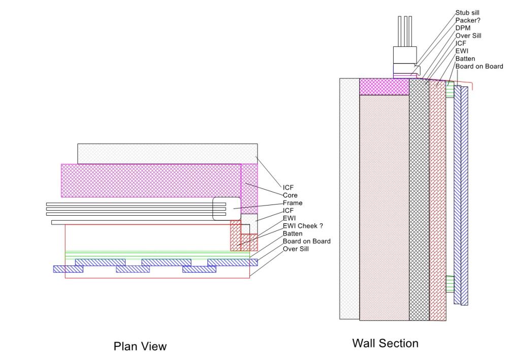
  20. Following on from my Foundation post, I want to get the detailing correct on the windows, this is spurred on further by reading this post My build will be with PolySteel ICF, 50mm EWI, Board on Board vertical cladding. UPVC windows. I'm thinking of using a stub sill on the UPVC window and then an Aluminium over sill. Using the sketch by @Babak in the above post, I have come up with the following Questions: 1: I'm thinking I need to add a packer (compact foam?) under the stub sill to allow for the over sill to be sealed - is this correct? 2: I'm thinking of adding 20mm EWI on the reveal to form a cheek, so the window can be sealed to this? 3: DPM, this need to be under the sill, over the outer wall and sealed, also out past the side of the reveals with an upstand. This detail would be very difficulty with Std DPM, so was thinking of using strips of peel and stick EPDM? or would Triton Liquid Membrane be better? To finish the reveals I'm looking at possibly using Black Soffit board as this will give a neat easy to seal finish against the frame.
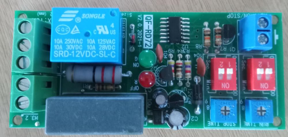
  21. This has been discussed on here before. My treatment plant runs 24/7. That is the Compressor runs 24/7. I have read that switching it off there is a chance that water can syphon up the air tubes. SO I was wondering if I was to turn it on and off hourly I would reduce the risk of any damage by syphoning and reduce the running costs by 50% We have a large plant 12P and currently only 2 people using it. when the cabins are fully occupied then this may jump but the reality I only ever see 6/8 people max every day. (it was sized by SEPA- I had no choice) I have found this little board that does what I need, turn on for x time, turn off for x time repeat. any thought on this as a plan would be appreciated. The setup would be temp, until the house is built then I may come up with a better solution but for now the treatment plant is plugged in, so was going to put this in line just after the plug.
  22. Jenki

    Cabin builds

    Since the last blog, a lot has happened in a relatively short time. The last blog was Stage 1 of the Amenity block, needing cladding and the roof, and as I'm sat here early in the morning , with the wind constantly blowing 20MPH, 2mm rain p/h. and a toasty 8 deg. inside the static, which is our home now - yey. The Cabins are complete. A lot of work and a move thrown in to the mix since the middle of August. The cabins are stick built on site, under the supervision of Building control, this means that the insulation and detailing falls within the small building regulations and thus U values are quite tight. The positive is that they will be relatively cheap to heat year round. The downside was we spent a lot more on insulation. The process was the same as the amenity block, the foundation slab was cast, and the floor insulation (120mm PIR) was sat on top of this and a radon barrier with floating chipboard on top. 6inch walls with glass wool insulation. Due to the extreme cost variations and difficulty getting hold of Frame therm 32, the walls were filled with a mixture of Frame therm 32 & 40, I managed to get some at Ā£18/ roll in Bradford and dragged it up with me, collecting some over ordered frame therm40, from Stirling on the way (thanks Market place). The bottom line was that I needed to add 25mm PIR inside to get the 0.21U required. The Roof was 120mm fibre glass coated PIR, with Firestone rubber bonded direct. The original plans was to clad the pods in Black Metal, but after some thoughts through BH (Salt in the air etc, we changed to Scottish Larch. We had 300, 4.8M lengths delivered from Huntly area. Mandy spent around 2 weeks solid staining these both sides and edges black. she was amazing, this was not an easy task. I think I painted 3/4 of 1 plank before I was off doing something else. The Orange look would have been too harsh, so we decided to stain them , and hopefully as the Larch ages and the stain fades they will eventually take on the natural look of Larch. Another tweak to the design was to cut the corner off the bathroom. allowing for 2 double beds, thinking that as our customers will in the main be only staying for a day or two, the bed was more important than sitting areas. My biggest concern was heating and hot water. I've asked on here before, and was thinking of using a 300l UVC, but was never happy this would supply enough hot water for two cabins and up to 10 people. - so either the expense of a Heat pump or direct immersion. I had laid 20mm MDPE pipe x 2 to each cabin from the amenity block. for the H&C supply. We bit the bullet and decided to supply the hot water via 2 off Cointra CPA11 open flue caravan heaters (LPG), I was concerned if the temperature would be ok, especially as the water travels between 3 & 6M underground . This was compounded further, later on, as we started having problems with the same heater in out static. Low temperature HW and problems when the wind picked up over 15MPH. Too late to worry, money was spent and It was suck it and see. Fitting the Open Flue heaters in the Amenity block created another issue, so we have ended up with a little extension on the side of amenity block that houses the two heater, basically its like they are outside, but inside. I have insulated them, but I will have to add a small heater with PID control (Job to do) to ensure the water does not freeze inside the boilers. For the hot water I fed 10mm PB pipe inside the MDPE pipe and hope the flow rates and temperature would work.... (I thought about asking on here, but sometimes you have to bite the bullet and see) We have installed UPVC DG windows, and I created MDF reveal liners, this allowed for the plaster boards to be fitted flush to the liners, with face mouldings to finish. I taped and jointed the PB, but to be honest it was a pain, due to the number of butt joints, on a couple of occasions I nearly went and bought some Multi finish. In general were happy with the finish, but it has confirmed that this WONT be happening on the house build. Mandy wanted a feature wall (interior design is where I stop), and the en-suite seemed to be a good place for this. We had just enough Larch left over, so Mandy cut and ripped this down, sanded one face and painted in various contrasting (I think that is what she said) colours. I helped a little with the first row or two install, as it does have some 22.55deg bevels, then I was back to to the other cabin sanding and filling. Due to the success of the Air to Air HP in the static, we decided to install the same in the cabins, this way we know the heat all year round will work. As this was a little after thought - external cladding was complete, I had to be creative with the internal pipe run, I created a box / shelf which can be seen in the photos below, this now acts as a cup holder with some cup hooks. The Bathrooms were clad with shower wall cladding. a Boxed in WC allows for all the utilities to enter and also houses the Wireless access point, which is powered POE. from the amenity block. Once the bathrooms were fitted, it was time to see if the HW works. Its a resounding yes. we had -4deg (This is how I know I need to stop the boilers freezing). but once I'd managed to thaw the boiler out, we were getting 40Deg in the cabins. The showers are not power showers, but they work really well, better than an electric shower. and heat up time is around 35 - 40 sec. The boilers have worked in 30MPH winds, so the issues with our static are just that and I'm still exploring the why. As we stand today 1 cabin is ready to let, and we are waiting delivery of 2 beds for the other cabin. 200m of livestock fencing in the new year will see this side of the project complete.
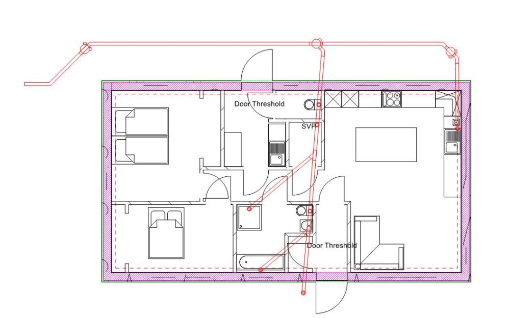
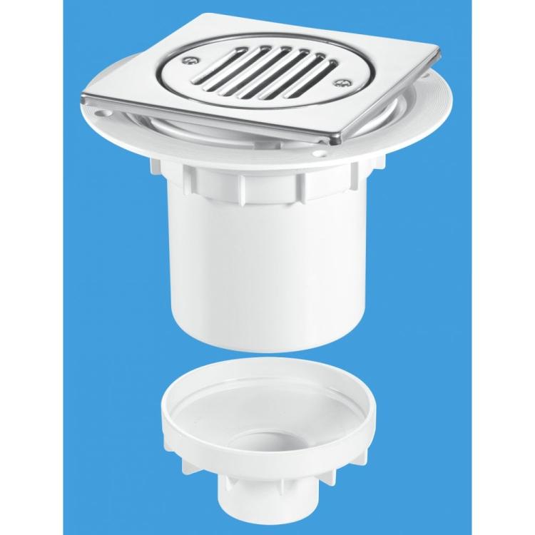
  23. Could you please cast your informed eyes over my drainage plan, and tell me if I've missed anything. I've used a NHBC tech sheet for some guidance, namely if I use a rodding point (bottom of the diagram) I can then branch off the main run for Bath and Shower. The two WC's and SVP will be connected with a Y branch and 45deg coupler to give a larger radius. SVP will be in the plant room and vented through the roof, I plan to use this for the waste for Utility basin, WC basin, and drain / blow off for UVC (150L UVC) Lastly I plan to have a walk in tray and want to use this or similar trap which will be connected to the 110mm pipe. (The House slab in the shower area will be left lower, so I can form a tray with screed later.
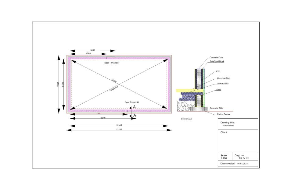
  24. First of a few posts, Having lived in the Highlands for a long time, (5 months and counting), We have had a re-think on the construction of our house. The decision is two fold, firstly the increased cost of stick build and insulation, plus the delivery costs, secondly the Weather. Its windy and I've never really experienced the issues with (constant) driving rain until now. If it rains its driving rain. ICF will be dearer, but not by much, and then with some tweaks to the design and the foundation, a simpler (thus cheaper) Air tightness detailing I'm not sure there is a lot in it. SO that's it, were going to build with ICF, and the decision is to use POLYSTEEL blocks, with EWI on the exterior. SO down to the Questions. My site is rock, the house plot is currently stripped of all top and sub soil down to the bedrock. The excavation results in depths of 350 - 500mm below the original ground, but this is sloping to the SW corner approx. 800mm drop to this corner. I will be breaking out some of this rock to reduce the slope. Once I've got this more level, the initial idea is to lay the radon barrier on the rock (sand blinding under the slab area) then shutter a 600mm trench strip for the concrete footing. The idea being that the radon barrier will not have any protrusions for services. 1, DPC - Poly steel says I don't need a DPC - ? Thoughts and comments please. The sketch shows the section. 600mm block sat on the strip foundation. If I opt for adding a DPC, then I'm introducing a moment in the footing and thus more reinforcement will be required. 2, The Visqueen would then be lapped up the wall, but not returned into the blocks? 3 How does my detailing of the thresholds look? - With Poly steel, the cavity is closed with 6*2 treated timber. I was thinking that as the doors need low thresholds the the door should be positioned on the external EPC of the block, and strapped back to the timber. Be Kind... 040123_Foundation.pdf
  25. I'm posting as a non Boffin, in search of ideas. I want to set up a weather station so in the future I can use this for weather compensation, but also want this information to have around the house. Additionally I have a project in mind that having wind speeds available, and being able to use windspeed as a signal may help. So I suppose the question is can I hack an of the shelf system and interrogate the data from say an RPI? Or should I go down the route of building one based in an RPI? At some point I will want to use an Rpi to monitor the house, and create a PV divert, but this will stretch my abilities as it will require some remote / wireless monitoring as my Electricity meter will be 50M from the house. But all this said I don't want to be tinkering with it all the time and it needs to work without me here.
×
×
  • Create New...