
ProDave
-
Posts
30861 -
Joined
-
Last visited
-
Days Won
427
Everything posted by ProDave
-

Now I know how old illegal septic tanks get away with it......
ProDave replied to ProDave's topic in Waste & Sewerage
Then they are not fit for purpose then are they? Building my new house, I had to jump through lots of hoops to get a CAR permit before building control would issue the building warrant. All good and correct. But they are also supposed to ensure pollution does not happen and deal with it where it does. If they don't even bother checking the basic details of old systems that they register then how can they be performing the most basic of checks to see if those are up to date and okay, or old and in need of upgrading? Quite shocking really at the total negligence I am seeing. -
Now I know how old illegal septic tanks get away with it......
ProDave replied to ProDave's topic in Waste & Sewerage
My complaint to SEPA about their negligence has been sent. I will post any reply if I get one. -
It is correctly behind a cage as when it blows off it could be near boiling water coming out.
-
It is a requirement in Scotland (and probably elsewhere) when selling a property, you have to register any private waste treatment system with SEPA. I have often wondered how old systems with a septic tank discharging to a watercourse continue to get away with it and why SEPA does not enforce them being upgraded. Well now I know. I have just registered the septic tank at our old house with SEPA. This still complies with the general binding rules as it is a septic tank discharging to a land drain. Well upon submitting my registration, ALL I provided was the property address, my email address, tick a box to confirm it serves between 1 and 9 properties, and tick another box to confirm it has been in use for more than 2 years. Then give payment details so they can fleece me of £170. I then expected to have to provide some details about the system, where it discharged to for instance. but NO. My registration was approved immediately. So no wonder I continue to see old systems discharging straight to a watercourse, they don't even bother to seek ANY details of the system you are registering to confirm it complies with the general binding rules. Why do I feel this is incredibly poor value for the £170 I have just given them. If my blood has not stopped boiling by the end of the day I will be complaining to the head of SEPA.
-
Yes "fit just enough PV" is a common mass market builders trick to gain a couple of extra SAP points to scrape through.
-
Fence alongside neighbours fence.
ProDave replied to Discoeye's topic in Landscaping, Decking & Patios
The only time I had this was a neighbour who when a fence blew down, took the splintered bits, "rebuilt" a panel and put it back up. In the end I suggested I put up a new fence. I took the two posts at the ends, put s string line between them and put up my new fence. In the middle I had "gained" nearly 2 feet of garden the original line was that crooked. The neighbour never complained. -
Basic Heating Control Understanding Help
ProDave replied to Shaun McD's topic in Air Source Heat Pumps (ASHP)
I have a dislike of 3 port valves but that dilike is 3 port mid position valves. You can use a 3 port 2 POSITION valve to switch from DHW to UFH but that does not help you if you want two manifolds operating independantly or a mix f UFH and radiators where you will be better off then with three 2 port valves. -
Making OSB air tight
ProDave replied to MikeSharp01's topic in Environmental Materials & Construction Methods
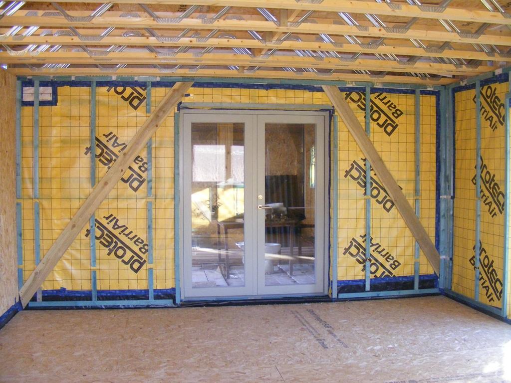
Protect Barriair was the cheapest I could find: It comes with pre taped edges but I did not trust their adhesive and taped with Tescon Vana as well (the blue tape in the picture)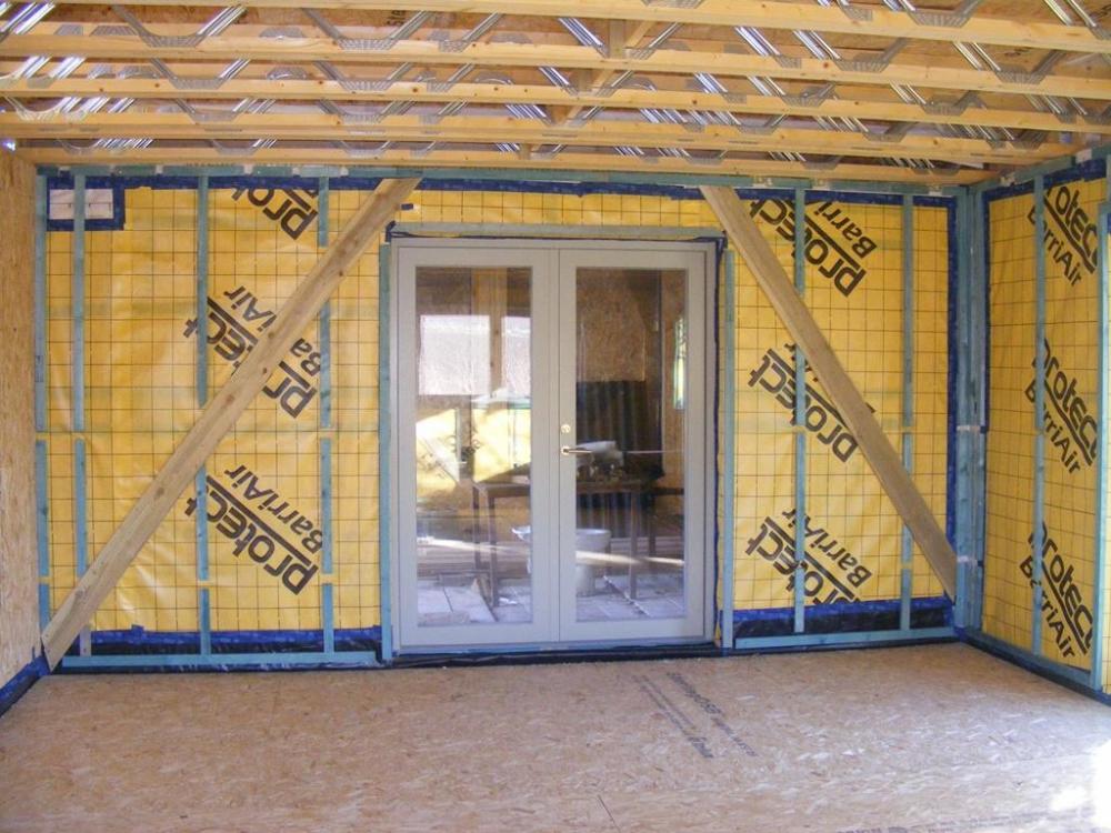
-
Basic Heating Control Understanding Help
ProDave replied to Shaun McD's topic in Air Source Heat Pumps (ASHP)
1: Most ASHP's have a temperature probe that goes into a thermostat pocket on the tank. 2: Most ASHP'will have some form of call for heat / thermostat input. 3: Weather compensation will lower the temperature of water to the UFH when it is less cold outside to get the best COP from the ASHP. 4: I would personally have a 2 port valve for each manifold and one for the DHW tank. 5: you have a room thermostat for each zone, not each loop, a large room or zone will be multiple loops. All dealt with by the manifold control box. An alternative school of thought on a very well insulated house where the heat input is low, is don't have individual zones, have the whole floor as one zone. 6: I would always have at least 1 room stat per floor. The problem with all these general answers, is the details of exactly how each ASHP communicates and deals with the other heating components is not a standard thing and it varies a lot from one make of ASHP and the next. So expect the detailed design to be very ASHP dependant. -
ASHP, how to decide - I just don't get it!
ProDave replied to Jimbo37's topic in Other Heating Systems
If they do that, you have dodged a bullet, they would not have been a company I would want to do business with. -
ASHP, how to decide - I just don't get it!
ProDave replied to Jimbo37's topic in Other Heating Systems
The "ASHP Industry" is really doing it's best to sully the reputation of ASHP's and drag it down to the level of cheap double zlazing. For a new build that we assume is well insulated an ASHP makes a lot of sense. It is just a shame you get silly things like this where they won't tell you anything or the other thing you get is the silly over inflated prices of MCS installers. As it is a new build do you have the insulation levels and expected air tightness, then you can easily do the heat loss calculations yourself using the spreadsheet available on this forum and design your own system. And if you want to avoid all the cloak and dagger nonsense you have , just buy the kit and employ a plumber and an electrician to install it. The Grant one is probably the easiest for a DIY install. -
It really is up to you. Depending how much the ground has been built up, it may settle later. I just got it as good as I could and if it settled and dips formed I just filled those in again later.
-
Gap for washing machine, is 600mm ok
ProDave replied to cwr's topic in Kitchen & Household Appliances
Are these built in appliances or free standing? -
Scaffold external then internal
ProDave replied to CalvinHobbes's topic in General Self Build & DIY Discussion
If you are going to buy scaffold, then buy one of the system scaffolds like Kwikstsge or Cuplock. Whatever is available. They are really a scaffold tower system where you can join as many towers together and build whatever height you are likely to need for a self build. Very simple to erect and change about. For inside use you can build a single tower and put it on wheels just like a scaffold tower and move it about. It is so useful that at the end of the build, I did not sell it all, I kept enough to scaffold one wall of the house. It is just so handy to have when you need it.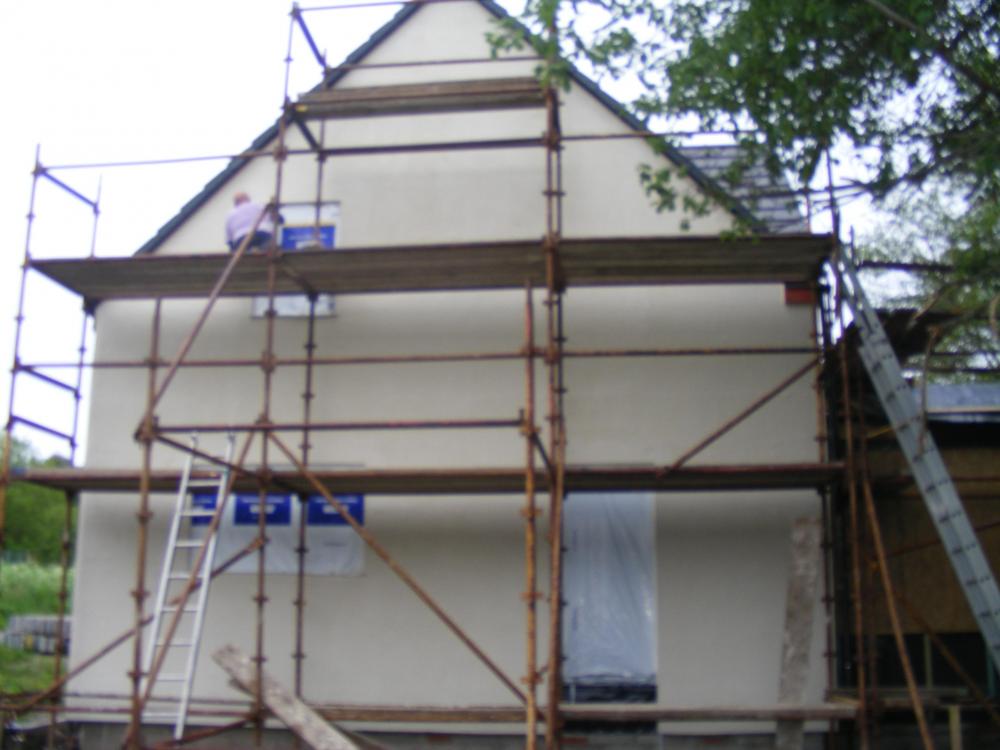
-
When I last had a "proper job" earning enough to pay higher rate tax, the hourly rate if you worked it out was a mere £15 per hour. But that was 20 years ago. I've been a sole trader for 20 years now, and now charge £30 per hour which some will say is high others will say it's low depending where you are . I only ever did a little sub contract work on sites, not for me. I just work direct for my clients far simpler. I don't see why companies not employing sole traders should make a shortage of sole traders for self builders to hire?
-
I bought probably the same 600W inverter from ebay, mine is grid tied so the shed panel is not a one trick pony it adds to the house power if nothing in the shed is using it. Beware those cheap Chinese inverters are not built very well. Mine failed in less than a year, inspection showed 2 of the transistors forming the H bridge short circuit. I replaced them and it works again. What I noticed was very little heat sink compound on any of the transistors, before the case used to run cool. Now it is re assembled with plenty of heat sink compound the case runs warm when it is working hard showing it is now actually working as a heatsink and 3 years later it is still working.
-
I sat on the balcony with a cup of tea today, put 2 biscuits down while I got comfy and the wind blew one away. So yes that ICF like that would worry me until tied down to something like stakes in the ground.
-
No I was lucky, but it would not have been a machine to go contracting in. Fuel filters kept blocking, I bought a job lot and replaced them regularly, probably something nasty in the tank. And I broke the king pin that the boom pivoted on. That could have been messy but it hung on one side until I could get a new pin and drove the old pin out with the new one, so it never all collapsed. the tracks were steel but well work, everything was old and well worn, but it worked and at the end I sold it for exactly what I paid for it.
-
Where @Jenki is, there are not many days when the wind is low enough for midges to bother you.
- 13 comments
-
- 1
-

-
- the windy roost
- caithness
- (and 2 more)
-
There are quite a few of us on here that bought our own digger and used it for most of the build. I did my own foundations up to the concrete then the builders turned up and took over from concrete pour onwards. They started off by saying I would never survey it, mark it out and dig the trenches in the right place on my own, but then admitted I had done a very accurate job, there was just one corner out by about 100mm and that was because I could not get the digger square on for that corner. It took us 10 minutes with a shovel to square off that corner to get it right. I used it for all the site preparation first, services, moving soil around and it's final task before I sold it was the basic landscaping of the garden.
-
We found you need very little "plant room" space, and it all ended up distributed around the house. A Monoblock Air source Heat Pump, most of the works are outside. You might need some pumps, valves and expansion vessels etc inside somewhere. Hot water tank wants to be positioned central to points of hot water use to minimise delivery time. Ours is in an airing cupboard partitioned off a bedroom. MVHR is best in a warm part of the house, but can be put in a loft id the ducting is properly insulated.
-
Total Control heating tariff phaseout
ProDave replied to Crofter's topic in General Self Build & DIY Discussion
As long as you get a 5 port or 5 terminal meter, it will do that. The 5th terminal is the output that is only energised when it is at the cheap rate. But Smart meters have come along and messed things up. You can aparently get a 5 port smart meter, but not all suppliers seem capable of actually making them do what it says on the tin, and lots of horror stories of the 5th output not turning on and off or the metering times matching the switching times. So if you do switch, ask for Economy 7 or preferably Economy 10 if available and don't mention smart meter and if that comes up in discussion say you don't want one. You will ideally need 2 immersion heaters one to come on whenever the cheap rate is available at the bottom of the tank, and another you can turn on at any time for a boost. If your tank will only take 1, then Horstman do a clever gadget that will let one work from the off peak supply with a manual timed boost. -
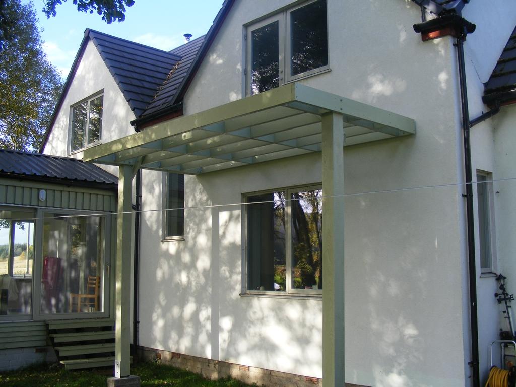
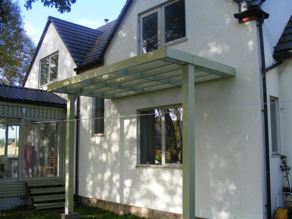
You don't have to be precise if the size of the PV roof ends up larger just cantilever the end, a bit like I did with my balcony I did the same, poured 2 concrete pads for the balcony legs at foundation time, and only recently uncovered them and completed the job.
-
ASHP winter additional heating ideas?
ProDave replied to ashthekid's topic in Air Source Heat Pumps (ASHP)
What is your monthly energy use now, now that the heating is off? In the absence of any other metering, that will give an indication how much of your usage is heating and how much is other stuff. Even in winter the other stuff uses more than the ASHP. Only when you know WHAT is using all the energy can you look into making it use less. -
Total Control heating tariff phaseout
ProDave replied to Crofter's topic in General Self Build & DIY Discussion
I guess if there was nothing registering on the normal meter? I once connected an electric boiler to the total heat board for a customer, it certainly seemed to fit the description of a heating appliance. In that situation getting 24/7 cheap rate almost made an electric boiler make sense.