


IanR
-
Posts
1857 -
Joined
-
Days Won
6
Everything posted by IanR
-
 When you say a "contemporary barn style", do you mean a contemporary re-imagining of a traditional barn, or of a modern barn/shed? Traditional barns do tend to have a 45°ish pitch roof, but modern barns/sheds will have a 10° - 15° pitch. I don't know what size of dwelling you are seeking, but from your comments it suggests a moderate to large dwelling. I may be wide of the mark, but the below proportions follow the form of a modern agricultural barn/shed and give a GIA of circa 300m² under a 6m ridge with a 10° pitch. Perhaps you could post some images of what you are thinking of.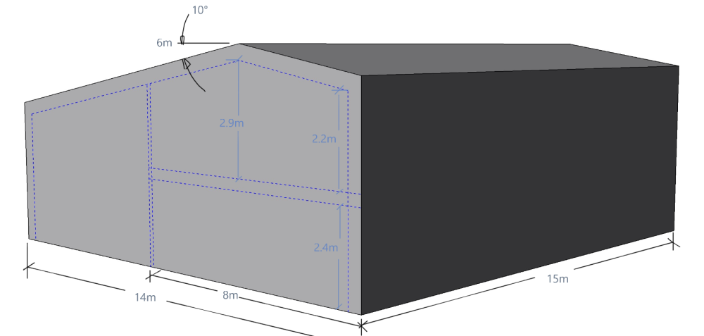
-
Ideas wanted to pass Part O Simplified modelling or to use Dynamic modelling?
IanR replied to Susie's topic in Ventilation
I didn't look too much into integral blinds. Internorm at the time only offered blinds on opening sashes, and they were then between the 3G unit and a 4th pane. Norsken, who I was also considering, did offer them within the sealed unit, but I felt the cable going out through the spacer was an unneeded risk to the unit. I do wonder if there's likely more radiated heat from a blind within the unit, especially for a dark blind. Integral blinds were also more costly than external blinds. -
Ideas wanted to pass Part O Simplified modelling or to use Dynamic modelling?
IanR replied to Susie's topic in Ventilation
You've said "no" to 'Shading provided', but your three large windows on the Southern façade appear to have an overhang, which would provide good summer shading to those windows. If you need more shading, you could consider external blinds on the 3 windows on the Eastern façade. They need to be automated to be effective, so it's not the cheapest option, but should be able to be hidden under the cladding, so no need for any planning changes. -
The planners may well be open to a change, but you'll need to request it formally, hopefully just by varying a condition (drawing update). Once you know what your preferred roof finish is it's worth a chat with the planning officer.
-
Is the roof finish detailed on the drawings? You likely have a condition that states the development must be in line with the "named" drawings submitted as part of the application.
-
They've a new version which can take an SD card for simpler data transfer. It also appears to include the Bluetooth module. Works out around £75 incl. VAT and delivery for an 8Ch temp logger. https://www.ebay.com/itm/115695655888
-
Is the Farmhouse within an urban setting? My understanding is urban green space are designated areas within cities and large towns that should be kept clear from development to allow open areas for health and well being as well as biodiversity. Perhaps you can explain how it may effect the area around the Farmhouse, in case we have different understanding of "urban green space" You're more likely to hit issues regarding development not protecting the scene of the Listed Building, or if the farmhouse is not within the settlement boundary then rules against development in the open countryside, which would need to be navigated around.
-
It's going to be pretty negligible on a new build, you can mitigate less efficient plan view profiles. To the planning officer the local vernacular is more important than you achieving the ideal U value with the least amount of insulation. You're better off arguing against what the Planning Officer is putting forward as the local vernacular. Although if their argument is sound then compromise will get you a positive outcome far quicker than trying to tell the planning officer they are wrong.
-
The heritage/conservation Officer is unfortunately entirely correct. Your current planning relies on the conversion of the existing buildings, which planning rules require them to be Structurally capable of conversion. There is no route to planning for a new build by arguing the existing buildings are not structurally capable of conversion. If that's what you have argued and have provided evidence to the LPA it's likely you are already stuffed. I'd withdraw your application and consider your next steps carefully. You may need to apply for a Certificate of Lawful Development, to check if the LPA still accepts your original planning is still valid. You are likely to need a new Structural Survey which confirms its structurally sound, but some how doesn't contradict the new survey you just shared with the LPA.
-
The industry is already responding to the need for 22kW home charging, having listened to their customers. It may take time for some brands to introduce them as it often pushes the need for a different cooling strategy for improved efficiencies, so may not be easy to upgrade.
-
EV A/C charging at 22kW will become more common in the 5 - 10 year future, as battery capacity increases. If you don't install 3 phase initially, make it an easy upgrade in the future so you're not stuck with 7kW charging at home, otherwise you'll find yourself paying a premium for DC fast charging at public charging points more often as you can't get enough charge at home - epically with multiple EVs in a household.
-
Your inundation pond is intended, in part, to be a site for "aquatic local wildlife". In England, you can't discharge within 50m of it, including your leach-field site, without a permit from the EA.
-
So in terms of u value, what can you swap a zinc roof for?
IanR replied to CalvinHobbes's topic in Roofing, Tiling & Slating
I've heard that said a few times, but it really doesn't to my eye. There's noticeable differences between a steel standing seam roof and a Zinc or Aluminium roof, but there's a huge difference to a single ply membrane roof with a profile stuck on it. It's a good value option, but doesn't have the same appearance. -
So in terms of u value, what can you swap a zinc roof for?
IanR replied to CalvinHobbes's topic in Roofing, Tiling & Slating
Since the ply deck the zinc sits on has a ventilation gap underneath, it's not doing anything for your U value. You can go with an 18mm OSB3 deck and save a little. A good alternative to zinc is Aluminium. Same ductility, so can be hand formed just the same, and more forgiving to condensation issues if there's any ventilation problems. Aluminum was about half the price of zinc for the product, but same labor cost, when I used it. Came in the same price as colourcoat urban steel. -
When is a cold bridge a cold bridge?
IanR replied to SimonD's topic in Energy Efficient & Sustainable Design Concepts
In PassivHaus terms a thermal bridge is any junction that has a calculated Psi value higher than 0.01 W/m.K. For my frame we tried to work on having a minimum 2/3rds of the nominal insulation thickness in the tight areas, but did have to drop to 50% in a couple of places. Calculated Psi values were still below the target. In standard building regs terms I believe a cold/thermal bridge is when it leads to a risk of condensation on the inner wall ie. the inner surface of the wall dropping below dew point. 21°C air at 65%RHI has a dew point of 14°C. Mould growth doesn't actually need condensation, just an RHI of +80%, but it does need those conditions to persist for a period of time (days). -
Thankfully, it won't happen, since a heating load at that level will keep the ASHP on. The heat pump will only switch off when the heating load is lower than the pump can modulate down to. Again, it shouldn't happen, as the heat pump will fulfil the heat demand, and not run at a lower rate than is required by the demand. It switches off once it's at the bottom end of its modulation, but the return temp is still rising. It has made me think about what happens when a defrost happens. There is a chance this could happen when the buffer has less that a full charge, and if the defrost takes longer than it takes for the heating demand to deplete the "flow temp" layer of water at the top, then then heating circuit will start to draw off water at what was the original return temp and will start to return water to the buffer at some lower temp. Since defrosting happens after the pump has been running for a while, the buffer is likely to be fully charged. Hopefully it takes longer for the heating demand to deplete the useable energy from the buffer than it does to complete a defrost event. The heat pump will often run faster than the heating demand, increasing the volume of flow temp water at the top of the tank and reducing the volume of return temp water at the bottom, with the thermocline boundary coming down the tank. The warmer water above the thermocline remains at flow temp, it doesn't cool. Since the flow temp water at the top does not mix with the return temp water at the bottom, the temp returning to the ASHP from the buffer continues to return at "return temp", until the buffer is fully charged and the thermocline gets to the bottom of the tank, at the same level as the inlet from the heating circuits and outlet to the ASHP. Now the return water from the heating circuit will briefly mix with flow temp water and this returns to eth ASHP where it can't modulate down any further but has warmer return water coming to it which would push up the flow temp above target, so it would switch off. Pretty much. When using flow temp control, there does have to be a breakdown of the stratification at the point the buffer is full in order to send warmer water to the ASHP to switch it off, but stratification will reform as soon as the ASHP switches off. Thermocouples at 25/75 of the tank height could avoid this, but would require more setting up on the control. I can't see an issue with it, so there's probably no reason to add the extra kit. Unfortunately I don't understand the logic to your 4P Buffer. What you describe happening can be explained by the buffer being fully mixed, so it could just be a volumiser in your flow or return line (return would be better). The their part controller does add to the evidence that your package is a one-size fits all package that de-risks the installation for the installer. Not really a problem as long as its able to keep the property warm.
-
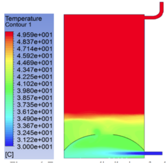
For which the time frame would be 10 to 100 times longer than the cycling of the heat pump, while it is providing heat to the central heating, so is not relevant to the performance of the heat pump. This also takes us deeper into the physics of temperature stratification in hot water tanks, where I do not feel this conversation needs to go - there are loads of references for it on t'internet. But, in short, the insulating properties at the boundaries of the stratified layers means that the convection currents from standing losses far exceeds any conduction between the layers so the cooler lower area actually cools quicker than the warmer upper layer and the tank becomes more stratified as it cools. The convection currents are caused by the standing losses at the tank wall which cools a very thin vertical layer of water adjacent to the wall. The water of the vertical layer becomes denser than its surroundings and slips towards the bottom of the tank, reducing the temp at the bottom of the tank. But none of that matters while the pump is cycling as the energy losses are minor and covered by the known standing losses for the tank. The standing losses for my tank, based on it being an average 50% charged during the call for heat period is 17.5W. or at a worst case CoP of 3............ 6W of electrical power. Maybe I've not allowed for the times the buffer is fully charged just as the call for heat ends, so gets wasted, but were talking really small numbers that are well within the potential error size of such predictions. If you mean by the water in the the lower portion of the tank, which is at return temp, increasing in volume, while the water in the upper area of the tank, which is at flow temp, reducing in volume so that the boundary between these to stratified layers (the thermocline) rises up the tank a little, the yes it "moves". Unfortunately that's not what I'm saying. There is absolutely no need for the pumps (ASHP & heating circuit) to have any similarity of flow rate or duration, which is lucky because they don't. The heating circuit pump will run continuously while there is a call for heat, while the heat pump will cycle on and off. In a correctly sized buffer, there won't be sufficient turbulence to cause mixing since the heat pump flow rate and pipe sizing will restrict the flow velocity to within the capabilities of the tank. The images and link I posted above show how robust the stratification in the tank is with the thermocline plane in the bottom 25% of the tank and close to a 12 l/m inlet that has only a plain baffle, flat sides, no porting, no pockets no swirl bowl in the lower face. Looking at the colour chart I would suggest the top 70% of the tank has remained at the flow temp, or within 0.5°C
-
But no mixing. The warmer water remains above the thermocline, at flow temp, and the cooler below the thermocline at return temp, the proportions of each body of water increase and decrease, moving the thermocline up and down the tank. No, the bodies of water at the two different temps do not mix. Their different densities keep them apart with the lower density water having the top spot. The volume of each of the bodies of water change in inverse relation to each other as either the heat pump adds more flow temp water to it or the HC removes flow temp water from it. Your version does destroy stratification where there would then typically be a linear temp gradient from top to bottom of the tank. My version requires stratification to remain in place, otherwise there is no point to a 3P or 4P buffer.
-
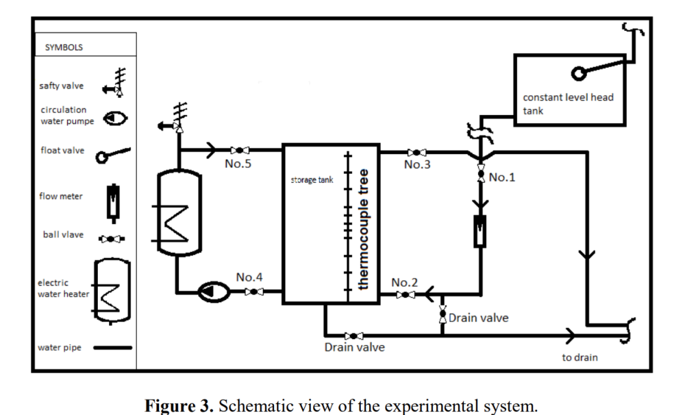
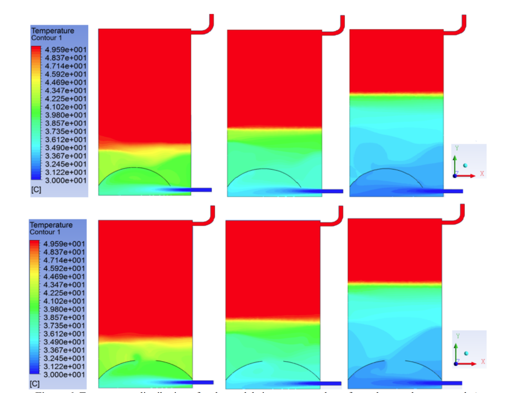
There is no mixing, assuming inlet and outlet velocities are within the parameters of the 4P buffer. In a running system where the buffer hasn't been allowed to cool off entirely, the tank is stratified with flow temp (minus minor standing losses) water at the top and return temp water at the bottom with a thermocline plane at some height in the cylinder between the two different temps (and different densities) of water, where there is a rapid temperature change. Depending on how "charged" the tank is determines at what height that thermocline is. I'm not sure what you mean by "bottom to top flow". What happens when the heat pump is off is the is the thermocline plane rises, the tank hold less energy, but the temp at the top stays the same (minus minor standing losses). The outlet to the CH will be within the upper portion where the temp is @ flow temp, so there is no need to increase the temp of the heat pump. No, you are removing and adding energy to the buffer by increasing and decreasing the portions of the buffer that are at either flow or return temp, so the "average" temp of the buffer is going up and down, but the temps at the top and bottom remain constant (minus minor standing losses) No, the buffer is to stop heat pump short cycling, so it will run for long periods, but then it will be off completely for long periods. Inlet and outlet fluid velocity needs to be kept within the parameters of the buffer tank by flow rate an pipe sizing. Much of the back and forth of this discussion seems to around the robustness of stratification within a hot water tank. It's being treated like a delicate phenomena that will disperse with any slight disruption, when the reality is far from it. It's used to good effect in DHW cylinders with mains water coming in at the bottom at double or triple the flow rates of a heat pump as well as heating elements within the tank that create convection currents and vertical mixing. Within commercial hot water storage tanks where stratification is not wanted anti stratification pumps have to be included to generate vertical mixing to get rid of it. The following may be of interest. It's not for a buffer, but for a solar thermal storage tank, where a CFD analysis has been run to determine the best baffle shape for the incoming water supply. The tank is equivalent in volume to a moderate-to-large buffer, is oddly rectangular in shape which will make reducing the inlet turbulence more difficult than a circular vessel, and importantly has a 12 l/m flow, which is over double my own 12kW ASHP. The simulated system is defined as: The analysis results have been verified against a physical prototype. A significant difference is the inlet on the demand side is at the constant water supply temp, that will be lower than the temp in the tank, at the bottom. I'm really hoping the following image doesn't confuse things more, but to me shows unbalanced, and completely unrelated flow rates between heat source and load, having absolutely no effect on the outlet temperature. Also of note, I feel, is the lack of disturbance of the thermocline until it gets into the lower third of the tank where the disturbance of the 12 l/m inlet is causing some turbulence with one design, but is better optimised in the other. The disturbance shown in the lower, cooler part of the tank, wouldn't be there if the incoming water was at the same temp as the body of water under the thermocline. To put the above images in context: Ref. https://iopscience.iop.org/article/10.1088/1757-899X/518/3/032052/pdf
-
That's the important bit. I'd trust Telford, as I would the larger heat pump brands that all invest in R&D to have developed the buffer to be optimised for its use. That Telford package appears to fit the retrofit market, where fitting within the constraints of the system being replaced are as important as eking out the last few tenths of SCoP. It perhaps also de-risks the installer from misjudging heating demand by including a buffer that may not be required in all circumstances which could also be at the expense of a few tenths of SCoP. The easiest improvement to efficiency you could make, is bypassing the buffer. You'd need to ensure that in the shoulder months a heating circuit was always open with sufficient volume and demand for a minimum ASHP 10 minute run time (longer would be better). You could also reconfigure the buffer plumbing, capping off two of the ports, and configure it as a 2P buffer in the return line. Either of the changes may effect the 7 year Telford warranty.
-
As was I. Yes, your 4P buffer looks challenged to work efficiently. But it's not a unique setup so the manufacturer has likely mitigated the compromises of delivering a tight package, as best as possible, assuming the heat pump, controller and tank combination are "manufacturer recommended". Are there indications that your system is not working as expected? ie. heat pump not meeting heating demand, or electrical consumption being higher than calculated?
-
Unfortunately I haven't been able to explain my understanding of the concept in a way that makes sense to you. There is no mixing in the buffer tank that needs to be avoided, and there is no need to minimise mixing of the heat pump flow with the stored water in the tank, as it will be at the same temp. The flow rates do not need to match, and are unlikely to ever match entirely. Even with those unequal flow rates, the water in the buffer will not mix (it does a little, but not enough to effect performance). When I say the water does not mix, I mean vertically mix. ie. the water at the top of the tank, at flow temp, does not mix with the water at the bottom of the tank, which is at return temp. The heat pump has to be sized to cover the entire heating demand. The choice of a buffer is to protect against short cycling, so by definition the heat pump is over-sized for the heat demand. The heat pump will be off because its max return temp has been met, and it can't modulate down any further, so switches off. It will cycle back on before all useable energy is depleted from the buffer - in fact it should cycle back on before the top of the tank falls below its lower hysteresis boundary and as it comes back on will satisfy 100% of the space heating demand, with the additional energy/flow available, recharging the buffer in parallel. Once the buffer is fully charged again, the heat pump will switch off.
-
I'm probably sounding like a broken record here, but the flow rates don't need to match - the top of the tank is at flow temp (minus minor standing losses). If the flow rate to the heating circuits is higher than that from heat pump, some hot water will be removed from the tank to support the heating circuit load. If the heating circuit flow rate is lower than the heat pump flow rate, then as well as supplying the heating circuit directly, the heat pump will push some additional heat into the tank, not necessarily increasing the temp at the top of the tank, but increasing the volume of water at the top of the tank which is at flow temp.
-
I do have a 4P buffer, feeding two UFH manifolds, each with multiple zones, as well as feeding an MVHR wet duct heater/chiller. The buffer is used for both heating and cooling. I also shut the buffer off from the UFH circuits to allow me to redistribute solar gain through the property via the UFH without having the HP on. I have no data logging, but have had no reason to question the systems performance. I did attempt to confirm the install was working within expected parameters during the first winter, but that wasn't easy. I had to run tests over night, since my property benefits well from solar gain and the background electrical consumption is more easy to control and calculate so that I could be confident in my power consumption estimates for the heating system from only the property's electricity meter. When I crunched the numbers, making allowance for standing losses, an extra pump, the longer run of pipes from ASHP to buffer that I have, I was surprised to see that, based on the heat pumps own heat meter, the HP operating at a higher CoP than the manufacturer suggested. I had thought that was likely to be me over-estimating losses and perhaps the buffer hadn't entirely cooled to ambient before I started the test. The Brendon Uys report may have provided another explanation which is his suggestion the CoP from the manufacturer is based on the H4 boundaries, where as I had assumed it was on the H3 boundaries, hence me making allowances for the standing losses and pump. For me a 4P buffer's ability to remain stratified is not the difference in flow rates between the primary and heating circuits, but the actual flow rate. The higher the flow rate the larger the buffer needs to be to keep the disturbance within the horizontal plane.
-
The design of internal ports and baffles or pockets is to avoid vertical mixing. The cooler water coming in at the bottom pushes the warmer water out at the top, but remains as a layer of cooler water under the warmer water, ie. stratified. "Mixing" is not part of their function, they are designed to minimise mixing. I'm not clear on 'hydronic balancing' within this context. I've only heard it used with regards separate heat emitters and ensuring they all receive the same flow temp. With regards to "why 4 ports", it's because 4 ports, in combination with stratification: ie. not at a mixed temp, but at the ASHP flow temp (minus minor standing losses) Yes, with all things equal, system volume determines ASHP run time. If that additional volume is fully mixed, and the heat pump is off, then the heating circuit flow temp will reduces linearly until the heat pump comes back on, and will then increase linearly, inline with the hysteresis of the heat pump control. With a 4P buffer, if you were to accept that it remains stratified, the flow temp to the heating circuits does not reduce (apart from minor standing losses) between heat pump cycles***. A stratified 4P buffer allows for a wider hysteresis, which can then allow longer cycle times of the heat pump, if required. *** I would expect a small drop in flow temp to the emitters when the heat pump cycles back on, until it gets up to the desired flow temp since the inlet to the buffer from ASHP is at the same or similar level to the outlet to the heating circuit. I don't know you are missing anything. You are believing 4P buffers mix, and I'm believing they remain, to a large extent, stratified. As you have pointed out, there's not much point in a 4P Buffer that mixes, if they did there are other alternatives that could avoid an additional pump.





