IanR
-
Posts
1842 -
Joined
-
Days Won
6
Everything posted by IanR
-
 As @SteamyTea says, it needs to be worked out for each house unfortunately. ACH is based upon the volume within the thermal envelope and the m³/h.m²@50Pa figure is based upon the gross inner surface area of the thermal envelope, ie. floor, walls and ceiling/roof.
 -
MVHR is key to PassivHaus principles due to the Max allowable air leakage rate of 0.6 ACH @ 50 Pa. The principle is to reduce energy loss via air leakage to the minimum reasonably achievable. A consequence of that is that MVHR is then required to keep the air in the house "healthy". As a rough approximation 0.6 ACH is typically around 1m³/h.m²@50Pa For English Building Regs, houses with an infiltration rate greater than 3m³/h.m²@50Pa do not require whole house mechanical ventilation as it's considered there's sufficient natural air leakage to keep a healthy air environment within the property. If you are above 3m³/h.m²@50Pa infiltration rate then increasing this further with an MVHR system will cause additional energy losses via the additional air changes caused by the MVHR, although +80% of the energy should be recovered at the expense of the electricity running the fans. MVHR is typically an expensive retrofit, and unless you plan to target sub a 3m³/h.m²@50Pa infiltration rate it will never pay for itself. Unless you plan to achieve PH targets, a more cost effective plan would be to achieve a >3m³/h.m²@50Pa, not install MVHR and use room extractors, perhaps with heat recovery, in wet rooms. Although I personally would want adjustable trickle vents in my windows to provide some level of additional, controllable ventilation if required. For info, I have a Airflow MVHR system, and the installation was designed by Airflow themselves. I remember one of their parameters being a Maximum infiltration rate of 5m³/h.m²@50Pa otherwise they wouldn't supply their MVHR system, with a recommendation of below 3m³/h.m²@50Pa.
-
I could have told you this would happen some day....
IanR replied to ProDave's topic in General Alternative Energy Issues
For me, this is the part of the Net Zero strategy that leaves me with some concern. The 14% FF generation is the higher end of the range, but, as part of the NZ Strategy this is Gas with CCUS. Unabated Gas powered generation is below 1%. My feeling is that CCUS remains, to some extent, snake oil and requires a development in technology that isn't guaranteed. I don't believe the industry is being honest about the level of CCUS that can be achieved today and are making unfounded predictions of capabilities for 2050. The NZ strategy currently, for the lowest cost technology mix to achieve Net Zero, I feel, will likely have shift to a higher reliance on either Nuclear or Hydrogen power generation, which will have higher costs associated than is currently considered. -
I could have told you this would happen some day....
IanR replied to ProDave's topic in General Alternative Energy Issues
It's certainly moved a long way from the original topic of Switzerland having a plan where they "may" have to ban EV's for "non-essential" journeys "if" the electricity imports they would normally rely upon in winter get restricted. Trying to connect that story to EV's not being able to replace ICE vehicles in the UK within the next 25 years (the target) is a bit of a stretch. -
Flow rates for Carpet, Wood ,Concrete and Tiles
IanR replied to Ben 64's topic in Underfloor Heating
With a heat pump you need to have the heating system running for much longer periods, this allows you to reduce the flow temp (once the slab is up to temp) and run the heat pump more efficiently. Your heat pump is only capable of putting around 1/3rd of the energy that a gas boiler can, into the UFH, so it needs to run at least 3 times as long to put the same energy into the house. Run it for even longer and you can run at lower temps and improve the efficiency. My system is heated via a heat pump with a flow temp of 32°C/33°C and a return temp of around 28°C, once everything is up to temp. The heat pump is allowed to run for up to 15 hours. It doesn't actually run for all that time, it just comes on and off during that period, when it needs to. At the start of the heating season though, it needs to run almost constantly for the allowed period for a couple of days to "charge" the slab up, but once up to temperature the slab stays a pretty a constant 21°C to 22°C at the surface. For heating, at the low flow temps, the heat pump is running at a COP of over 5. For hot water though the flow temp is 50°C, which drops the average COP a little. If you are struggling with getting your house up to temp, I'd let it run 24 hours a day until the target temp is met, then reduce the flow temps until you are in the 35°C to 40°C range where the heat pump efficiency will have improved, and then see if there's some "head room" in your system to start to restrict the number of hours the heat pump can run for. With regards to flow rates, this is more about balancing the system and getting each zone to it's target temp, at the same time. -
Flow rates for Carpet, Wood ,Concrete and Tiles
IanR replied to Ben 64's topic in Underfloor Heating
Flow rates are not set in stone so you can adjust these to suit your installation. But I'd check a few basics first. 45° is a high flow temp for UFH via heat pump. Do you know the return temp? Are you leaving the heat pump on for long periods or are you using it like a gas boiler, ie. trying to warm the house just during occupied periods? What's your floor build up? and pipe spacing? -
My architect suggest this for a family home, thought
IanR replied to Tennentslager's topic in New House & Self Build Design
Is your Architect a fan of Charles Rennie Mackintosh? https://www.bbc.co.uk/news/magazine-31855385 -
What do you think of Flextron for a zinc roof?
IanR replied to CalvinHobbes's topic in Photovoltaics (PV)
There's a fly-lead connecting to a small junction box at one end, that allows the arrays to be daisy-chained together. If "designed in" the fly-leads will be covered by a profile capping. -
What do you think of Flextron for a zinc roof?
IanR replied to CalvinHobbes's topic in Photovoltaics (PV)
Prices seem to be at a premium currently, unless you know differently. I've looked into similar to retro-fit on my aluminium roof. As well as the value, I didn't get an answer I was happy with regards how to replace them. The roof should have a 60 year life, but the PV 20 - 25, so at some point they will need replacing. When I asked, the manufactures had not run any trials with regards removing the modules and if damage could be avoided. -
Class Q - Steel portal barn conversion cost estimates
IanR replied to Stoph43's topic in Costing & Estimating
I'm going by the drawing provided that shows the outside surface of the Portal frame level with outside surface of the wall. I had assumed the profile sheeting is just in the upper areas, a short distance down from the eaves, as is typical with agricultural portal frames. Even if the profile sheeting went from eaves to floor, the 40mm that gives you, outside the portal frame is insufficient to stop a thermal bridge. You still need a rain screen on the outside of any insulation. The wording in Class Q is that you can't extend beyond the existing envelope at any point. How I dealt with that was to have an upper cladding outside of the portal frame, in the same way the original profile sheeting was, but have the lower cladding inset, level with the portal frame, in the same position the original walls were, which means the portal frame is still visible externally at the lower level, as it was on the original building. It is now recognised in the planning guidance that a Class Q Approval should be taken as material for a full planning. However that doesn't necessarily get you to a knock down and re-build. But it should at least allow the Class Q rule of not exceeding the existing building envelope at any point to be ignored, leading to the chance of brining the portal frame within the thermal envelope, and it should open up additional building works that are otherwise restricted by the Class Q.
-
Class Q - Steel portal barn conversion cost estimates
IanR replied to Stoph43's topic in Costing & Estimating
If the conversion is completed under Class Q then the converted building can not extend beyond the original building, so if the portal frame is visible on the outside there is no opportunity to enclose the frame within the thermal envelope. If it's not converted under Class Q, then it's best to avoid keeping the portal frame. Your drawings show the portal frame to be aligned with the external surface of the external walls of the original building. Under Class Q it would be best to leave these entirely outside the thermal envelope and avoid any thermal bridge. Since the uprights connect to the primary roof structure, I'd also leave the roof beams and purlins outside the thermal envelope, as steel has exceptionally good thermal conductivity. In order to not have the building performance compromised by the steel portal frame, I built an I-Joist timber structure (walls & roof) within the portal frame, dovetailing the timber structure around the steel structure, but not letting them touch. The Steel portal frame is still in place, including the roof portals and Z Purlins, which continue to hold up the light weight rains screen, which in my case is a standing seam metal roof. The timber structure supports the 300mm - 350mm blown cellulose fibre insulation in the walls and roof, as well as the mezzanine. The internal columns of the portal frame took some careful detailing to keep those outside the thermal envelope. You asked on PM for some more details on my conversion, so just in case you've not found these posts previously, I'll add them here. Fell free to ask any questions if something is not clear. -
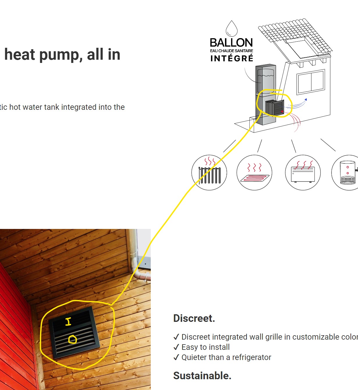
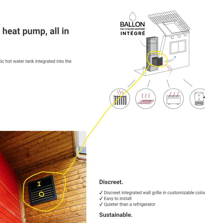
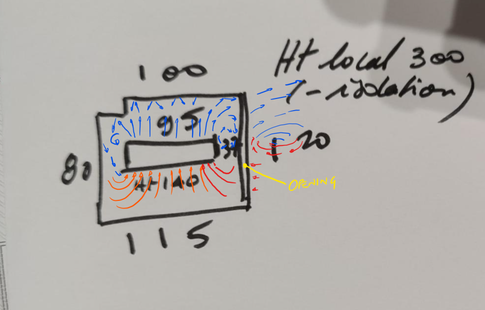
Yes, it's the fan speed that is moving 3000m³/h, which leads to the requirement of 12.5 air changes a minute The issue is putting a restriction in its path, ie. the ventilation grille. The smaller the cross-sectional area of the opening, the faster the air flow required to shift the 12.5 air changes a minute through it. That need to speed up the air flow adds resistance to the air path and makes the fan less efficient. ie. less air volume moved for the same electrical power used. The lager the inlet ventilation grille the better. The upper half of the door, with a louvered grille and perhaps a "wide" insect mesh (6mm x 6mm min) should be fine. I went with the exhaust duct sealed to the door as there is more detritus at ground level (leaves etc.) which won't enter the room if the inlet is higher, and also that the exhaust air starts at a small cross-sectional area (the diameter of the fan), and it seemed inefficient to me to allow it to expand into he room, and therefore slow down, before it then needs to speed up again as it "squeezes" through the ventilation grille. Just my engineering judgement, I'd have to model it to know if it actually made any difference to the pressure drop.
-
I've not come across these before, but they manage with discreet inlet and outlet ducting to fresh air and avoid any mixing, plus they are low power. Hopefully they are very well sound insulated, otherwise the household will wake up every time the compressor spins up. With regards to your set up, the double-line suggested the door opening. But even still, as drawn, I don't feel it would work, but, put the outlet duct up to the door opening and seal it against the grille so that all exhausted air goes outside and then have an inlet grille in the upper half of the door opening, open to the whole volume of the room, and it could work without too much pressure drop that effects efficiency. But this still requires an air change in the "tiny room" every 4 seconds or so. The smaller the heat pump the better for this set up.
-
To be clear, this is what I have understood from your description, the direction of air movement being perpendicular to the opening and causing significant pressure drops and restricted air flow meaning more air will be recycled within the room than comes in through the opening. You'll need to be specific about the model, the heat pumps I just searched from those brands were air-to-water monobloc external units, as are all the air-to-water monoblocs for domestic heating that I'm aware of.
-
a) it reduces the area of the opening. I don't believe it would work with an "open door", but it will fail quicker with a ventilation grille, as the cooling air inside the room will get mixed with even less fresh air. The sound insulated "boxes" that I have seen for heat pumps do not pull air from inside the insulated box, there is an inlet grille on one side and an exhaust grille on the other. b) your situation is worse as the direction of air movement is not towards the opening, it's across the width of the "tiny room" with solid walls on inlet and exhaust side. If the planned insulation levels are high and you plan good air-tightness, then 11kW seems high to me. While my own property is a recent conversion to very low energy losses, I'm at around 1650m³ and have a 500l DWH cylinder and find my 12kW heat pump over-kill. I didn't fully trust in my heat loss calcs that suggested an 8kW HP would easily manage, so went for the next size up. I've got away with it as I have a 200l buffer for the UFH, but my HP has a very easy life.
-
Unfortunately, it couldn't possibly work. The data sheet for the heat pump states that the unit moves just under 3000 m³/h of air, and the room you are suggesting it goes in contains less that 4m³ of air. The ventilation grille won't allow effective throughput of fresh air so the unit will continually recycle the air within the room. I would expect that within a few minutes of the unit switching on to heating mode, and the air in the room being recycled up to 10 times a minute though the unit, the air temp would have dropped to a temp below its effective range. Also: & Have you done any heat loss calcs? If you are undergoing a significant renovation then there is opportunity to improve insulation and air tightness levels and with your description of the property as part of a small house, then the unit you are suggesting maybe larger than you need. Although even a small unit couldn't go in the "tiny room" you describe. Do you own the roof? Could the outside unit go up there?
-
Class Q - Steel portal barn conversion cost estimates
IanR replied to Stoph43's topic in Costing & Estimating
Hi @Stoph43 and welcome. I'm now living in Class Q conversion that I got Approval for 6 or 7 years ago. My Approval was in the early days of what was then Class MB and there were no Appeals to get a wider legal opinion on the interpretation of the rules. My LPA wouldn't accept the Class Q Approval being material to a full planning application for a knock down and re-build. There are now Appeals and case law that say a Class Q Approval should be taken into account when considering the merits of a full planning app. If I did mine again, that's exactly what I'd do. The existing steel structure compromises the Engineering of the conversion and the compromises either need to be accepted or you need to spend money to resolve them. I chose the latter, and am very happy with the result, but it would have been cheaper to do a comparable new build. This is not a reason to walk away from a Class Q though, the compromises should be priced in to the value of the plot. Costs will be dependant on your aspirations for building performance, levels for finish and site related costs for Services hard landscaping etc.. It's not likely to be less that £2K/m², but could be more than £3.5K/m², unless you plan to do a lot of work yourself. I'd suggest you speak with an SE sooner rather than later. The existing structure is unlikely to take the loads of a habitable mezzanine, and possibly not the framing to hold the insulation. Yes there are insulated profile cladding options, but think carefully about these and how you would use them without exceeding the existing buildings dimensions, achieve reasonable air-tightness and mitigate the thermal bridging of the existing frame. -
Sounds like you won't need to upgrade the transformer. I needed to pay for an upgrade whether I went 1 or 3 phase, and it wasn't much more for 3 phase. I was charged £2,819.60 to upgrade the pole transformer from 50kVA to 100kVA. I'd asked for a 45kVA connection, but they put 100A on each phase so I assume my connection is at 69kVA. Sounds like you are doing a knock down and rebuild, mine's a conversion of the same size foot-print as yours. Built to PassivHaus standards (un-certified), my 12kW ASHP is overkill. I can't see you need to go to the expense of a GSHP, unless you are doing so for other reasons. I wanted 3 phase for the workshop, the house doesn't really need it, although it does offer you other options for PV and car charging.
-
Strip footings or insulated raft?
IanR replied to Selfbuildnewbie's topic in Insulated Concrete Formwork (ICF)
Only by doing the heat loss calcs, which I did for my current property, but I never compared insulated raft v. B&B with all else equal, so could not pick out the delta for that comparison. Mine was a walk from a heat loss of around 55kWh.m²/year for a "traditional" conversion (from a cow shed) to a little under 15kWh.m²/year for what I eventually built. The big factors in that improvement was good floor/wall/roof insulation levels, high performing windows and doors, no cold bridges and very low infiltration rate. What percentage of the improvement is down to the insulated raft + elimination of cold bridges I don't know. The decision was made easy for me as when I actually costed both options, and included insulation and screed costs for the B&B option, the insulated raft was cheaper. -
Strip footings or insulated raft?
IanR replied to Selfbuildnewbie's topic in Insulated Concrete Formwork (ICF)
Agreed, if only considering the performance of the floor. The air temp under the B&B being a lower temp than the ground under a raft won't have that much effect on the overall performance. The external walls and internal load bearing walls however, will perform far less well in a strip foundation with B&B setup due to the cold bridging. Probably worth pricing both out to check on that. You'd need to include the cost of insulation and screed on the B&B floor to compare to an insulated raft. An insulated raft is not difficult to do, well, at least up to the pour. On your first one it would be worth getting a ground works team in to help with the pour and power-float to de-risk that part. That would be a days work for a team of 3 or 4. AFT will come and do it with 1 person, if you supply a couple of labourers. -
Strip footings or insulated raft?
IanR replied to Selfbuildnewbie's topic in Insulated Concrete Formwork (ICF)
Since you are specifically asking about an insulated raft, rather than a traditional raft, it's not entirely fair to compare costs to strip foundations, unless your going to spend extra on the strip foundations to get their performance up to the same level as an insulated raft. An insulated raft allows you to easily remove all cold bridges at the floor wall joint and with some careful design, achieve the same at the door thresholds. If you are paying for removal of spoil, I'd also say they are actually cost competitive against other highly insulated floor options. If you are on flat ground then the an insulated raft is a shallow dig. A 0.11 U Value is achieved with around 300mm of EPS insulation. UFH can be set directly in the raft and a screed is not necessary, so another saving there. All in all materials costs are actually lower than strip foundations + block and beam + insulation + screed for the same U value, but, an insulated raft needs a structural engineer's costs adding to them to get them through building control. For all their benefits they remain a niche product. I have an insulated raft from Advanced Foundation Technologies Ltd. and wouldn't consider doing foundations any other way on my next self-build. -
Problems with glazing fitted into green oak frame
IanR replied to Robert Clark's topic in Windows & Glazing
Boxing....it's a hare....townie! -
What does "thermal mass" mean to you? It's not got a definition that everyone agrees on, and there's no units for it, making it open to interpretation. A masonry skin, outside an insulated cavity, and therefore outside the thermal envelope could be considered "thermal mass". Similarly a poured concrete raft, sitting atop an EPS former and therefore within the thermal envelope could also be considered "thermal mass". The effect of both is to dampen the diurnal temperature variation, and assist the insulation in stabilising the internal temperature of the house. Concrete sitting inside an EPS sandwich would be just as effective as if it were either fully inside or outside the insulation layer.
-
Rookies diving into the passive house deep end
IanR replied to Jake Smith's topic in Introduce Yourself
Hi Jake, welcome! Sounds like you could be an asset to the Forum, and hopefully you can pick up some titbits along the way. -
Problems with glazing fitted into green oak frame
IanR replied to Robert Clark's topic in Windows & Glazing
For timber windows, the current U value requirement (1.6) is carried forward into the new regs until 14.06.2023, so makes no difference if you read the old or new regs (for timber windows only)