Russdl
-
Posts
1785 -
Joined
-
Last visited
-
Days Won
6
Everything posted by Russdl
-
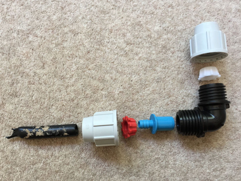
It turns out we have a 3/8" Alkathene water main. Is 3/8" big enough to produce the goods when it comes to connecting to the new house? To set up a temporary standpipe I've got a Plasson 90° elbow (with a blue adapter) the internal diameter of the blue adapter is about 7mm. Does anyone know of alternative connectors that don't restrict the 3/8" Alkathene, I'm guessing that 3/8" is too small and 7mm is way too small?
-
@CC45 that’s been our best guess up to now, pretty heavy duty earth though! @ProDave we have the electric DNO on site in a couple of weeks so I’ll get them to peer down the hole.
-
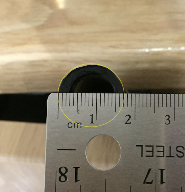
Thanks Nick. It's definitely sub 20mm external diameter, no more than 17.5mm, should there really be a 2.5mm tolerance? The plan is to have a standpipe off the main at that location as a temporary supply and then, when the build is complete, run the main from that point to the new house. I was thinking of a 90° elbow up to the standpipe and at a later date, replace the 90° elbow with and in line join for the new supply. Are there massive flaws in that plan?
-
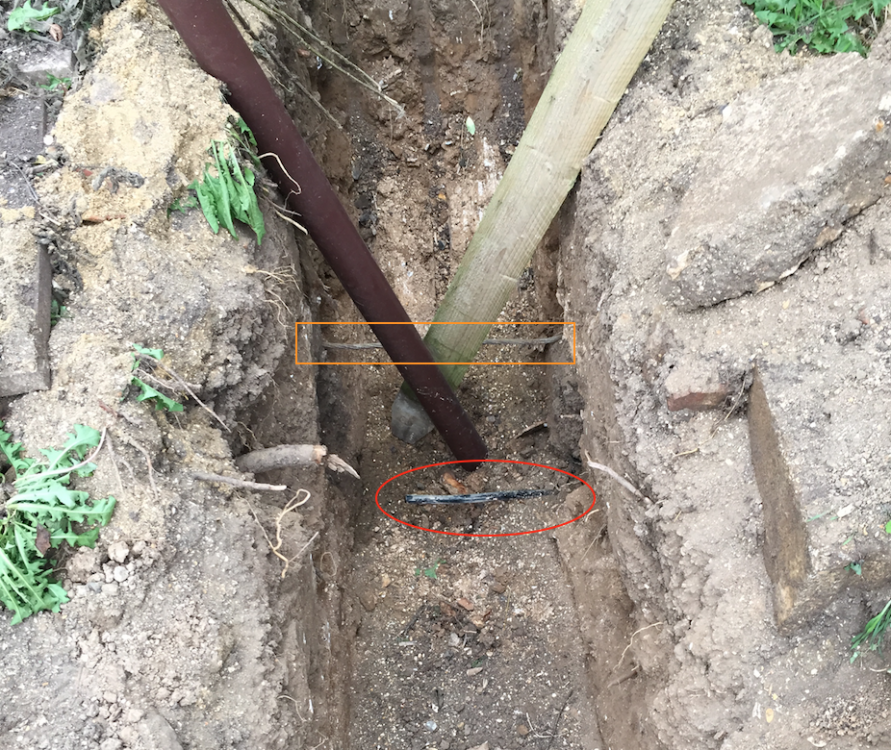
Well, a friend bought his mini digger round and we've found the water main... It's not iron or lead, it's black poly (is that the correct technical name?) We also unearthed a steel cable buried around the same depth, can anyone tell me what that is for? Should I hide it quick? The water main itself is externally just shy of 3/4" and internally it's pretty much bang on 1/2". So, have I got a 3/4" or 1/2" black poly main? I'm assuming it will be imperial as I suspect it's been there for decades (in new money, externally it's 17.5mm).
-
Wouldn't that be fun!
-
@Onoff. Thanks, thats just the kind of practical advice I was looking for ?
-
(Minor thread drift). I know where my water meter is and so I can make a pretty good guess as to where the supply enters the plot around 50m from the meter. I want to set up a building supply prior to demolition so I dig down and find the supply pipe... And then what? It's probably a sixty-ish year old pipe. Are there special techniques, tips and tricks to cut it and fit a standpipe and how do I connect a standpipe to the supply pipe? What bits do I need (apart from a mini digger).
-
Wow. Good luck Vivien, @ProDaves comments make for pretty scary reading. I hope a simple (and cheap) solution is forthcoming.
-
Roof build up insulation ideas.
Russdl replied to Russell griffiths's topic in General Self Build & DIY Discussion
We are planning on using Tata, MBC say it should be laid on OSB and the OSB should be on battens for the air gap. Can you give me a link to the Aussie/US stuff? -
Great news ?. You seem to have everything under control. I’m looking forward to seeing the photos as well, and hopefully I’ll pop along when MBC are there.
-
Who has used, is using, PHPP?
Russdl replied to Dreadnaught's topic in New House & Self Build Design
That is really interesting because the main player using the I beam construction would appear to have many more certified passive house's out there than MBC using (what you would consider) an inferior construction method to achieve it, that's reassuring as MBC is our company of choice. I didn't realise you'd done that. As my design has concealed gutters I think I'll be stuffed on the eaves but should be able to get a bit in the ladder frames. -
Who has used, is using, PHPP?
Russdl replied to Dreadnaught's topic in New House & Self Build Design
Yeah, I guess I was trying to cheat the system! I've changed it to 55 W/mK and reduced the % of nail plate due to all the holes in them. As you predicted, the impact is minor. The last PHPP expert I spoke to suggested replacing the nail plates with OSB webs (which the manufacturer has agreed to do at no extra cost) but I have to say it seems like complete overkill and I suspect I won't bother doing that. I suppose the bottom line is that I have more faith in @JSHarris's U value calculations than the PHPP expert I spoke to, and I'm starting to feel inclined to ignore the PHPP expert (which means that was an expensive conversation!) -
Who has used, is using, PHPP?
Russdl replied to Dreadnaught's topic in New House & Self Build Design
@JSHarris Certainly can, off to look at windows now ? The nail plates in my model have very little impact but they are not as accurately modelled as yours. -
Who has used, is using, PHPP?
Russdl replied to Dreadnaught's topic in New House & Self Build Design
@A_L Some very interesting observations there and thanks for the attachment, and yes 'twin stud' construction. -
Who has used, is using, PHPP?
Russdl replied to Dreadnaught's topic in New House & Self Build Design
@JSHarris I've modelled the nail plate over the central 122mm noggin (it would of course extend either side of that, as per your CAD drawing) but I found that an easy way of modelling it. I didn't consider the fact that it's full of holes but I guess I could just reduce my % of metal in the frame to account for that. -
Who has used, is using, PHPP?
Russdl replied to Dreadnaught's topic in New House & Self Build Design
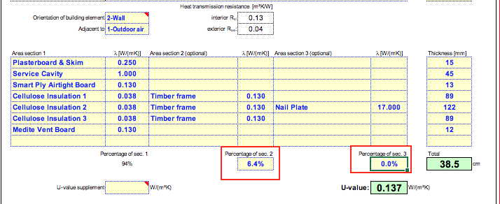
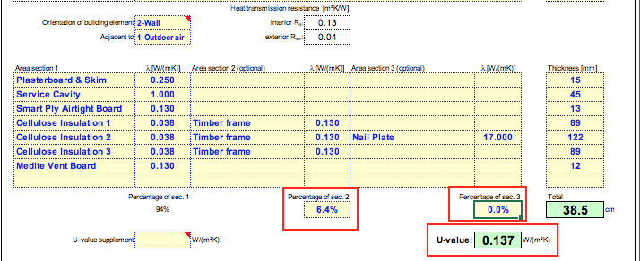
@JSHarris I've no doubt that is accurate, and much different to the figure I've achieved in my PHPP. Can you see any glaring errors in the data I've put in to my spread sheet that has resulted in my U value of 0.137?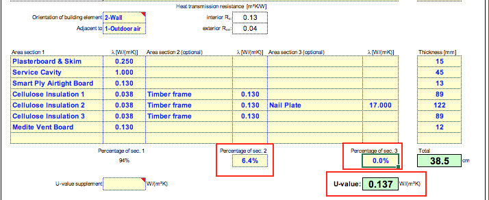
-
Who has used, is using, PHPP?
Russdl replied to Dreadnaught's topic in New House & Self Build Design
Wow! ? I should have guessed! I'm just scratching the surface, clearly! -
Who has used, is using, PHPP?
Russdl replied to Dreadnaught's topic in New House & Self Build Design
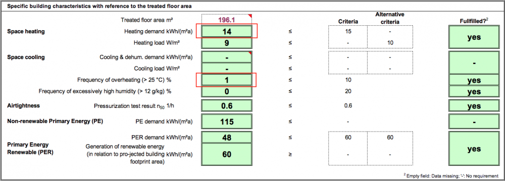
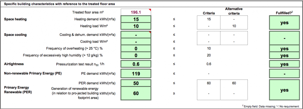
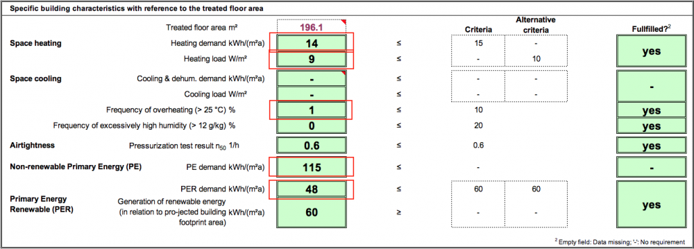
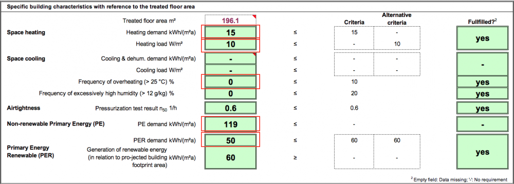
We're planning to use the same timber frame as @JSHarris (and many others) and if I enter the wall construction into PHPP with a U value of 0.12 I get this: If I then add the % of timber frame (6.4%) and nail plates (0.016%) in the wall (as explained to me by a PHPP expert) it changes the U value a fair amount and pretty much everything else on the verification page: The difference between those 2 verification screen shots is purely down to the 6.4% timber frame in the wall construction and the 0.016% of metal nail plates, I find it quite amazing the changes that produces and, as I said earlier, I've not even started on modelling the roof construction into it's component parts. Has anyone else modelled a timber frame wall construction in such fine detail? Is this going over the top or a useful exercise?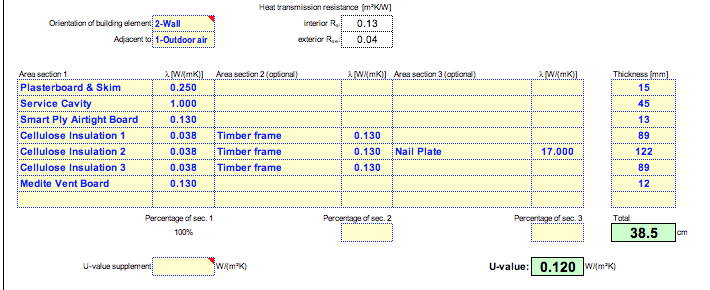
-
Who has used, is using, PHPP?
Russdl replied to Dreadnaught's topic in New House & Self Build Design
In case we had to get shot of it before we popped our clogs is the main reason. Or maybe lack of faith in me getting it right ? Probably the latter. Probably justified, time will tell. -
Who has used, is using, PHPP?
Russdl replied to Dreadnaught's topic in New House & Self Build Design
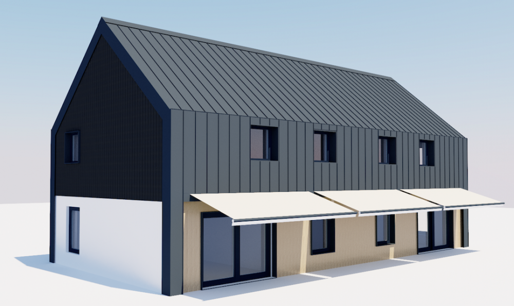
Still on the fence, but falling towards 'not' (if permitted, we all know the rules) I've loved and loathed messing with the PHPP in equal measure. My geo-located Sketchup model has probably guided me more than the PHPP as you can produce the sun/shadows for any time of the year/day and it really reinforces that gut feeling. It's around 190m2 and may look something like this.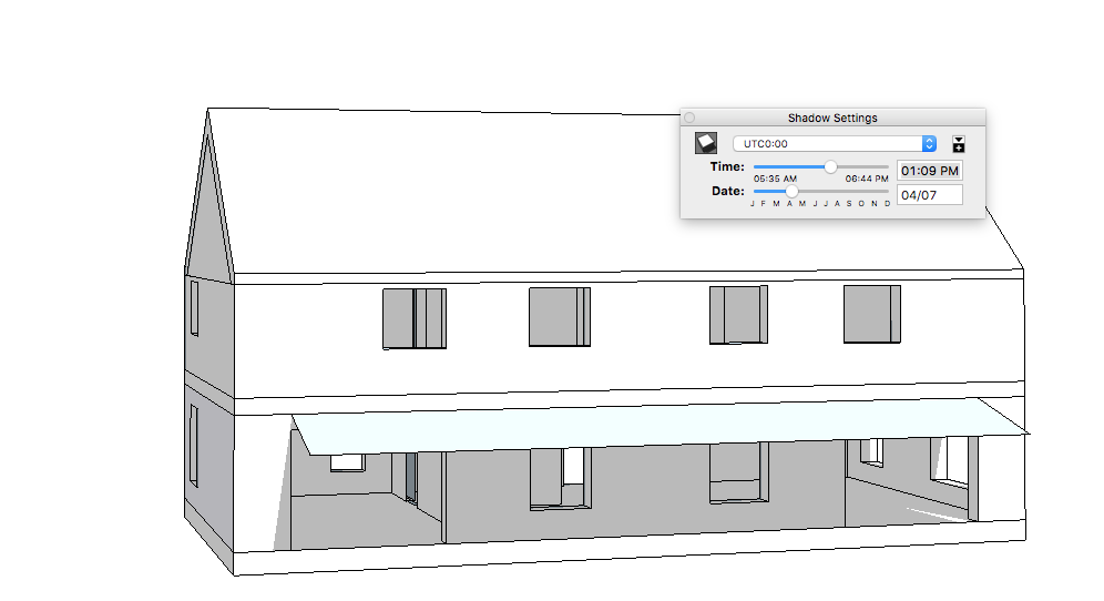
-
Who has used, is using, PHPP?
Russdl replied to Dreadnaught's topic in New House & Self Build Design
I think you've hit the nail on the head there. The thing is Mike, mine looked like that (without any shading) but I'd made a mistake in the data, which wasn't spotted by my second PHPP expert (and his credentials put him right up there - expert that is), and when I corrected my error it was 10% 'frequency of overheating'. I'd always planned on shading for the SE and SW elevations because I reckoned it would need that by just 'eyeballing' it. After fixing my error and putting the shading back in I'm down to 0% overheating. I think. That's what my PHPP says at the moment anyway. -
Who has used, is using, PHPP?
Russdl replied to Dreadnaught's topic in New House & Self Build Design
Out of interest @Dreadnaught are you going for certification? I was on the fence but very happy to use PHPP to guide me. The better half was/is very keen that we get certified but after our last meeting We are now not so sure. -
Who has used, is using, PHPP?
Russdl replied to Dreadnaught's topic in New House & Self Build Design
That's it - it's out in the open! Here's my post to @Dreadnaught to add to the debate. ~~~~~ Hi Dreadnaught. So as not to drift the thread too much from the 'house cooling ideas' I thought I'd message you directly. Are you doing the PHPP yourself and if so, how are you getting on? My first dealing with PHPP was with an 'expert' who was a complete clown so I bought my own copy of the PHPP and started entering the data myself - and, if I'm honest, I've been struggling with elements of it. After a while I went to see another 'expert' who agreed to review my attempt, he was definitely much much better but he'd still missed some school boy errors that I'd made, which I discovered after learning stuff from my meeting with him. Also he was going into minutiae that I hadn't for one moment considered. For example, the timber frame company we will most likely go with use nail plates to join elements of the timber frame, his modelling of this in the PHPP proved that the claimed U value was incorrect (if you factored in the amount of timber in the walls and the metal nail plates), so I've taken that on board in my PHPP but not even started on the roof construction! Despite that I've managed to get my overheating down to zero using awnings on the southern elevation of our planned house, but I wonder, have I? What else have I missed... I'd appreciate your thoughts. Cheers. Russ. -
Thanks @Simplysimon & @PeterW, I’d found those sorts of things but I was looking for something much older, I don’t really know but maybe a circa 1960’s - 70’s one (or much older) with a few more curves and maybe a bit more character, they’re probably out there with the old post boxes and telephone kiosks but I’m buggered if I can find any. Failing that I think I’ll probably plagerise @MikeSharp01‘s design.
-
@Simplysimon (right, lets see if I can do this, quote from another thread that is) In another thread where I asked about Service alterations prior to demolition @MikeSharp01 posted pictures of a 'block house' he'd built on his boundary for all his service, and IIRC from @JSHarris's blog he did something not too dissimilar, but closer to the new property. I 'm leaning towards @MikeSharp01's solution for my own plot and was searching eBay the other day seeing if I could find a second hand roadside electricity enclosure, those big old green metal things, and make that work, but I couldn't find any perhaps because I don't really know what there called. Any way, here goes with Mikes picture. (Crikey it worked!)