


TerryE
-
Posts
3806 -
Joined
-
Last visited
-
Days Won
30
Everything posted by TerryE
-
As I said there is a universal solvent for the OSMA brand that contains a mix of solvents that work liquefy both ABS and PVC, but if the resulting two plastics are immiscible then you don't really get a true weld, do you? And if there is some bonding then there's no guarantee that it will be watertight as you can easily get gaps. Send a bit risky to me. After all, all I am talking about it when an ABS branch connects to the PVC-U stack, and this is also the weakest point for expansion cracks to form. At least a push fit spigotis designed for this scenario. Need to think about this one. BTW, I have 11 such 50mm and below branches connecting into my 2 stacks.
-
I am finalising my foul-water designs based on OSMA pipework. OSMA use 3 different materials for their soil and waste pipe systems: PVC-U (Unplasticised Polyvinyl Chloride) PVC-C (Cholorinated Polyvinyl Chloride) which is a PVC variant with better high temperature properties ABS (Acrylonitrile Butadiene Styrene) PVC-U is used for the heavy stuff such as the main 110mm pipes and fittings, and the PVC-C and ABS uses for the narrow bore wastes (50mm and bellow) as these need to be hot water tolerance. In general ABS pipework is cheaper than the PVC-C equivalent and slightly more robust. OSMA do a universal cleaner and a universal solvent which contain a soup of cleaners / solvents capable of cleaning both ABS and PVC. As far as I can see you can solvent-weld within one type, and also PVC-U to PVC-C, but I can't find any manufacturers that will endorse attempting to weld ABS to PVC-U, so you have to use some form of push fit boss connector at a PVC to ABS interface. So as far as I can see, if you want to avoid boxed-in push fit connections then you must use PVC-C waste systems. Is this correct?
-
IIMO, you have to be very careful to read the T&Cs attached to the architects proposal. Who owns the IPR and the copyright on the work that you have commissioned? The architects practice will often retain this and put strict constraints on how you can use their work. You might find that you can only use this work if you pay them to oversee the subsequent phases of the build. A total fee of 7% of the value of the project isn't uncommon, and this also means that you need to get the build independently valued, so you need to add in the QS fees that you hadn't budgeted. £2,400 sounds to good to be true, and the usual reason that things sound to be true is ...
-
Same as me Peter. The 6-8 week delay is in scheduling the actual ground works.
-
We've just got a basic one which is fine for what we needed. IMO, the bells and whistles are only worth while if you are doing a lot of level taking. You don't even need a laser receiver to work on your own if you make a cross T support and velcro your sighting rule to it; you just need to walk to and from the dumpy each measurement, which is fine if you are just doing the odd level check. But if you do buy a second hand dumpy, then you must make sure that it's properly calibrated -- a bit of a faff but easy enough to do. As to what to look for, try to make sure that its "only one owner / one project" preferably with the original boxing still intact. I'd avoid a knocked around builders hand-me-down.
-
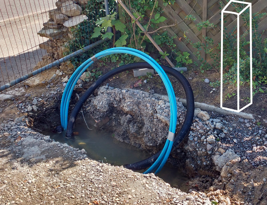
This was an occasional but recurring topic on eBuild, including a topic that Jan and I initiated. Our water supplier (Anglian Water) has a strict policy to the effect that: the pipe into the house must be a min of 75cm deep and their surveyor must review the house installation for compliance before scheduling any connection works on the public highway. (There is a waiver for approved installers but in practice these guys only deal with large installations.) The standard way to get around this is to do this installation in 2 phases: Install a standpipe and request connection to the standpipe. This triggers digging up the road and connection to your property including the installation of a meter, stopcock and double check valve at or near the boundary. This has a 6++ weeks lead time. When the house and plumbing is "finished", then apply for approval to connect up the final supply to the house. This has a 1-2 week lead time in our area. So you can parallel up the external works and 1st / 2nd fit with the roadworks for the costs of a standpipe and the extra site visit, which is often worth doing even if you are never going to use the standpipe in anger. What is crazy is that our water table near the boundary is about 150mm below the street level so IMO there is no way that A.W. will put their meter and stop cock at 750mm because it will be permanently covered in ½m water. I did suggest just making the standpipe available and fitting it at the same time as the digging, but no: there is an absolute rule: the Anglian survey engineer has to review the installed standpipe and standpipe tail for compliance with their guidelines before any groundwords can be scheduled.) See attached photo where I've marked the position of the standpipe; there wil be a second coil of MDPE from the standpipe. The black pipe is for the electricity supply. You can buy made up standpipes such as this one: PL34 Standpipe which costs £235+VAT and is as per attached image, but I will buy the bits and make up my own for about £30. One wrinkle is that A.W. insist that the bibcock must not have a hose connector -- so I can either spend ~£30 for one without a hose connector of use a £7.50 one and angle-grind off the hose connector. Hey-ho!!
-
Thanks @Nickfromwales and @Auchlossen; much appreciated. This ensuite is in our son's bedroom, and he can be a bit of a dozy bugger. One thing that worries me is that this ensuite is tucked into the the rear gable, and the apex is tight at the frame head so we've only got about 3 cm floor clearance unless I start thicknessing the frame head down further, and so we can only have a small thresh on the door. IMO the disaster scenario would be if say he had a shower and dropped a flannel over the tray trap so the floor in the ensuite would then start to fill and top the door thresh spilling into the untanked bedroom. We have a secondary drain in the floor near the door in the wetroom in our Greek cottage. Is it worth doing something similar in this ensuite? OK, this backup drain might never get called upon, so the tanking integrity doesn't need to be of the same robustness as the main shower tray. However, it seems that using this as an emergency overflow would be a lot more to be preferred than topping the door bar and dumping water into the bedroom!! PS. How to you like my model toilet pan?
-
One dimensional thinking
TerryE replied to tonyshouse's topic in Energy Efficient & Sustainable Design Concepts
OK, I think that we agree on the issue, but maybe diverge on labelling it. In my view it would be extremely difficult to model this stuff in 2 or 3D. I would describe this more as understanding the limitations of a 1D model and therefore where the assumptions that underpin the model start to fail materially. External corners; window and door framing, etc. But the failing here might not be modelling ones but engineering ones -- for example slab PUR has excellent U values so long as there aren't any convection gaps which will allow air to circulate back-to-front and pump heat out of the house bypassing the beautiful insulation barrier, or in my slab where 230 × 20mm rebar has the same thermal conductance as 8" of continuous concrete -
One dimensional thinking
TerryE replied to tonyshouse's topic in Energy Efficient & Sustainable Design Concepts
Yes, the issue isn't that you are losing an extra 30W of heat along a linear feature such as the centre column in a corner window. This isn't a great variation to the total budget in the grand scheme of things; it's that this heat loss occurs in a very small area and this can result in a surface temperature that is below the dew point for the house's absolute humidity, with this acting as a condensing surface. A local surface temperature drop of a few degrees won't be a problem. One of 10° or more will be. -
I see that the Karndean FAQ says that it isn't suitable for wetrooms, but is there any realistic alternative to tiling for upstairs wetrooms?
-
In the absence of other advice, it looks like we'll go with the JDK ones and the TP standard softwood frames with separate stop, as these are reasonable quality and the trade website is within 10-20% of comparable "best buys". We're doing all of the fitting ourselves. One issue here is that the final wall widths don't match any of the stock frames so I have to rip them on my table-saw and finish them in my planer thicknesser whatever I buy. This might seem a bit of a fuss, but at least this way I get the quality and accuracy that I want without paying £2-300 a day for a chippy whose finished work will just annoy both me and Jan.
-
One dimensional thinking
TerryE replied to tonyshouse's topic in Energy Efficient & Sustainable Design Concepts
Tony, a serious response to what I think is a serious point. 1D models have reasonable analytic approximations and can be numerically solved with some economy. With 2, 4 and 4 (time) D models the computational burden rises by orders of magnitude with dimension. Yes they can be solved but is the solution understandable? Is the input data set sufficiently accurate to merit the extra complexity? In a well designed passive style house such as the cellulosic filled Larson strut filled frame with a decent insulated slab then a 1D model will get within 10-15% of a decent 3D model, and at the same time the 1D approximation makes it easy to understand the forcing factors. Yes, as you improve the U values of your surfaces then the linear elements are a more important component, but IMO the issue here isn't modelling them, it is understanding the vulnerabilities and preventing them in the first place by design. If I look at our house, then the major design cock-up was nothing to do with the wall or ceiling make-up or 1D vs 2D modelling assumptions, etc.. It was that we have an external stone skin so Hillard, MBC Structural Engineer, made a simple mistake (IMO) which solved a structural problem but at the same time created a huge thermal bridge between the slab and the outer ring beam. OK, I spotted this in time to put a mitigation in place: that is by leaving the EPS300 slab framing in place and adding a layer of Foamglas Perinsul blocks between the slab and the stone skin, but this detail would have killed the performance of the slab if left unmitigated. Hopefully this won't be a solution for future builders in my position because Hilliard and I have discussed the best ways of avoiding this vulnerability in future designs which require a stone skin. The more spherical (blockhouse-ish, whatever) your house is then the more that the 1D model approximation dominates true life performance. Yes it is a terrible approximation if your house has many facets / reentrants, but the fact is that building this way might look architecturally interesting, but the real thermal performance is going to be crap however you model it. -
That's what we did. For a couple of months the main waterproof layer was the membrane -- even though MBC wouldn't warrant this -- but we had absolutely no problems. Then we lifted the stapling along the eaves edge and fitted the arras rail before the slater started work. We also wrapped the front face and the underneath is a folded aluminium L section as I discussed recently in another topic.
-
Your sketch up pretty well matches my description of what we've done. We used some arras rail from the local timber yard for the 90/45/45 section. The membrane goes over this, and the ventilation strip is pinned to this and the tile /slate sits on top:
-
Ferdinand, as I see it @oranjeboom has 3 remediation paths: (a) leave the wibbly high infill, levle and use a high U-value insulation, (b) dig out and relevel, (c) the external skirt option. 100mm of PIR might not be ideal but it will perform reasonably. Depending on the total area digging out and rewacking might only be a couple of days work and if necessary hiring a minidigger to avoid the backbreaking work. I would discount your external skirt option as it won't be as effective as the other two and is a major undertaking. So I would personally choose one of the first two, probably the second. This underlines the wisdom of the slab makers approach (and they used a fairly small wacker plate BTW) whcih was to lay the hard core in 50mm layers and level (using laser) and whack down each layer then finish with 50mm sharp sand whack and top up to final level using screed bars. I
-
The Great Thermal Mass Myth................
TerryE replied to Jeremy Harris's topic in Boffin's Corner
I think there are separate but related discussions about use of "thermal mass" (and yes, that meant to tease J) for external bulking and interior bulking. In my and Jermey's house the bulk of the thermal capacity is on the exterior shell to the living environment, that is in the slab and the the filling in the the Larson strut frame. This acts a huge high-stop filter on external variations. Any internal bulking is intended to top up heat losses. The is a lumped system, and any internal heat capacity and time constants need to be matched to exterior ones. IMO the main benefit of interior "thermal mass" is to act as an absorber of internal heat variations -- the odd 4 visitors, vacuuming, etc. But designing a total system to work effectively is going to be complicated. -
The Great Thermal Mass Myth................
TerryE replied to Jeremy Harris's topic in Boffin's Corner
Come on Nick, why the cynicism? If you remember I did a post on the eBuild forum where I did just that for my wall profile and did some time simulations showing the time response to various external temperature profiles, and I showed the cross-sectional heat profiles. The equation is the standard heat equation. OK, it was a 1D model, but that was good enough. It should that for the standard twinwall with an external stone skin, the time constant was so long compared to 24 hrs that I really didn't have to worry about diurnal effects or modelling them when doing my Heat balance calcs. A simple steady state approximation is perfectly adequate. At that point I stopped doing time varying thermal models - no point. -
The Great Thermal Mass Myth................
TerryE replied to Jeremy Harris's topic in Boffin's Corner
I was a mathematician by training, so I am one of those rare wierdoes who is comfortable thinking in equations. So if you are like me then this Wikipedia description is useful: Thermal time constant. The physics of this is dictated by what is called the heat equation, and this is classed as what is known as linear time invariant systems. This formula has the dimensions of time, that is you can measure it and quote it in seconds, hours of whatever time unit takes your fancy, and it is a measure of how sluggish your system is to respond to step changes in external conditions. Dropping the funny formula symbols, this article includes a summary: In other words, the time constant says that larger masses and larger heat capacities lead to slower changes in temperature, while larger surface areas and better heat transfer lead to faster temperature changes. I would say: the longer the time constant the more sluggish is the response to changes in external temperature. The time constant for the walls of my house with its external stone skin and twinwall filled with cellulosic filler is a few days, and because of this I don't really have to worry about diurnal temperature variations in designing my heating system- 122 replies
-
- 2
-

-
- thermal mass
- heat capacity
- (and 4 more)
-
Jeremy you are correct -- not pea-shingle, but a fine sharp stone, say 3-5mm. The comment about being weed-free is useful. Thanks
-
SUDS permeable paving bricks, such as these. They are laid on a sieved crushed aggregate then pea single. Note the little notches in the bricks which allow the water to drain
-
We use a concertina black aluminium roll the same as the one you showed above. MBC advised that the roof needed ventilation between the slates and the felt, so we went with that. Because we were slating rather than tiling, we needed a small kick at the eaves line. So we used a 3" arras rail with the long side to the sarking (we have a 45° pitch) with the felt on top of it and ventilation strip pinned on top of that. It was about 2cm high and slotted. The counter battens stopped just above the arras rail. Worked well. The slater had no problems .
-
Envy, envy. and it is a big garden.
-
Yup, I did a post on eBuild. We had originally planned to slate after the stone skin was up, pretty much as Ed @Construction Channel described in one of his recent YouTube videos, but my builder and his stonemason had a fall out and we had a small problem with planning enforcement which meant that we couldn't wait and had to do the slating first. The folded aluminium detailing saved our bacon and made this doable without compromising the look of the house. We did the detailing ourselves working ahead of the slater. This made sense to us both, as the corners were fiddly and took time to get right. This meant that the slater could bash on at what he was good at. A decent pair of tin snips and some round head outdoor Japan black screws are essential.
-
We used Kytun dry verges, and custom folds for our eaves and verges. The result is fantastic. Ordered direct from the manufacturer. Absolutely no issues. Both Jan and I are delighted with the result and the slater was impressed with the dry verge system. But it was a work of origami in aluminium doing the corners, etc.
-
I started to explain the physics of sharpening to Janet, but she cut me off after about 30 seconds with " I am really getting worried about you; you're becoming totally obsessed with this" and walked off. A truly sharp edge is formed by two mirror-like surfaces meeting at a V so that the edge isn't too cratered at a µm scale as "craters" are bowl-shaped regions of the edge that are blunt and which will crush the lignin chains rather than part them. But of course we can't obtain a truly flat surface in practice. Polishing involves moving a flat surface and a grit which is harder than steel against the steel, with a cascade of descending particle sizes of particles that are harder than steel, so a rough 120 grit diamond stone has diamond grains that have a mean diameter of 125µm. A 1000 grit wetstone has a mean diameter of nearer 15µm (remembering that the pit size / abrasive area effectively goes as the square but the volume removed as the cube ). So it takes less polishing as you go down the scale, so long as you don't make too big a jump between grit sizes. Stones can take you down to 1500 grit unless you are willing to pay a lot for a quality Japanese wetstone. It's a lot easier at this level to use a soft carrier surface (e.g. leather or MDF) and a fine grit -- a honing compound. A Cr2O3-based grit is down to the 1-3 µm size, and is normally sold as a powder or in a wax binder. (½µm is getting to optically flat dimensions). There are loads available on eBay, and specialist suppliers in the £5-£20 range. I don't have enough practical experience to recommend one as best value. Over to Ed @Construction Channel I think The WP article on sandpaper gives good background reading.
