TerryE
-
Posts
3822 -
Joined
-
Last visited
-
Days Won
30
Everything posted by TerryE
-
And my darling wife calls me anal for putting 1×Cat5E into every room (except my live-in son has two).
-
I was reading on this StackExchange topic that SSRs typically have a 1% heat loss in the internal thyristors or ~ 30W per "on" relay in my case. Not enough to merit a work around but in the case of my small equipment cupboard -- when combined with the waste heat from the 2 × SunAmp -- enough to include top and bottom ventilation into the toilet area (which has an MVHR extract in the ceiling). I like the idea that one guy mentions of paralleling up an SSR and a mechanical relay so you switch on the SSR for only a second or so, so that when you turn on (or off) the mechanical one, this as done at 0V across the contacts so no contact wear or sparking causing EM interference, and not material wastage from the SSRs which are only on for a few seconds per cycle. Very elegant, but not cost effective in my case
-
@JSHarris, Jeremy I'm not sure if you noticed this Q in the exchange, but I would value your opinion. Thanks
-
@peter if this is just a 220 VAC signalling route (ie. the current is in the mA rather than A) then a 2 channel opt isolated relay board based on the small Songle relays would do this fine. They are cheap as chips. (£4-8 in the UK.) Or even a couple of ITEAD Studio Sonoff switches that I mention earlier in the topic.
-
Sorry @PeterW, still no wiser on what the problem that you are trying to address is. You've given me a fragment of a solution that doesn't work (sorry for the oxymoron).
-
@JSHarris Jeremy, it looks like I will go with the Crydom CKRD2420 models. Thanks for the steer. As you say, you can control these through a 5V GPIO and there are no back EMF issues that you find with mechanical relays. There are £57.45 from Farnell and £35.09 from RS. Guess where I'll be getting then from? As you say, I am very reluctant to go to an unknown supplier for something like this as I will be putting 3kW through them. They've got some thumping heat sinks on them, so need decent airflow. Have you just got them mounted on a bare DIN rail or in some form of DIN enclosure? Peter, I am not sure why you'd need double pole or double throw for power switching applications. I would be interested in a little background
-
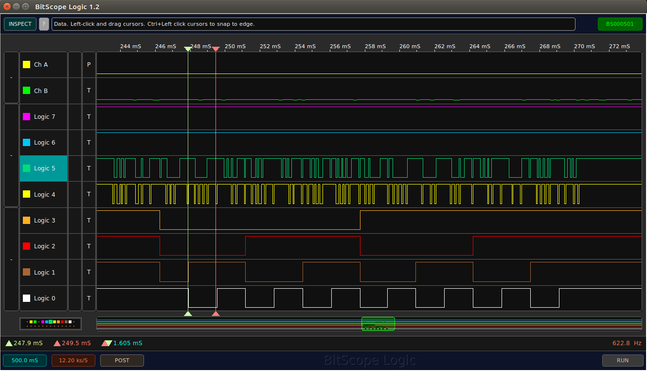
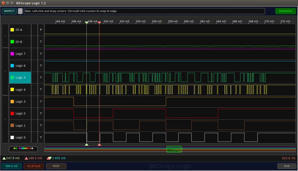
Not directly related to this thread, but something that I recommend for anyone needing to do hardware debugging is a Bitscope which you can get for around £80 (though I bought mine pre-vote for nearer £60). Even so it's for more than an order of magnitude cheaper then the DLOs we used to buy.
-
@SteamyTea, try logging over a temperature glide. If you haven't got the waterproof ones then put them in a metal box on the window cill and let them slowly warm in the sunshine. Or in a poly bag in water starting hotter or colder than room temperature. Then you can do the same sort of analysis as my first post. You don't need an absolute reference, just use an average, maybe excluding any obvious outriders. I've decided to source mine cheaply but use this sort of callibration technique to select matched sets. I don't need absolute accuracy, but I do need reasonably matched sets - say to 0.1° over the operating range.
-
I am happy to source my stuff from China because most comes from there any way, and there's little point in paying a 2-3 x mark up to some supplier unless they add value. Supply obsolescence is a real issue wherever you get your components from, so one thing I will be doing is to buy a 10-20 year spares holding as part of commissioning. E.g. if I am using Wemos modules, then buy 100% extra as spares.
-
I'll also so take a look at SSRs (solid state relays). The challenge that I find is not working out how to do this, because there are just so many solution options available, but rather picking a good one from the resilience and maintenance perspective. Cost is in the noise.
-
PREAMBLE NOTE: This thread was really a separate topic so split off from Logging from DS18B20s. I've just put together my first breadboard of my switch design and got is working in a couple of hours. I have to switch my 2 × SunAmp and the Willis, all of which have 3kW elements and the UFH pump. This is a little convolved because I want my electrician to install the 240V side and sign this off. So I will be using 4x pukka DIN rail mounted power relays to CE and relevant approvals. (such as the FINDER 22.21.9.024.4000 Power Relay, SPST-NO, 24 VDC, 20 A, 22 Series, DIN Rail). Their coils, in this case, will be driven by 24V DC inputs which draw roughly 1.25W to close the contact. The normal way to drive these from a microcontroller would be through a set of Darlington pairs (the UNL2308A gangs up eight of these pairs) and this chip is rated up to 0.5A collector current per pair. On the input side this chip can be directly driven by the esp8266 GPIOs similar to this PIC example: I still need to check if I need the the external Zener diodes as a free wheeling diode to avoid back emf effects. My fallback is to use a second bank of lower spec relays to switch the 24V. This might seem like over kill but the cost and complexity is in the noise. I mainly need my sparky to be comfortable with his installation. Hey Ho and onwards.
-
Martin, it looks like they're doing a fantastic job. Very impressive. Is the house a bungalow or just huge? I am also a little surprised that you thought that you needed 8 UFH loops in an MBC-class house. Still the way that they do it means that there is little cost impact.
-
@dogman, I would either cover those subs with the slip collars with a poly bag and tape this to the slip collars (so the concrete does grip the stub) or if the collar top is just under the FFL take a photo and remove it, but again a poly bag. The lads can then power float over it and you can tap through when the concrete has cured for a day or so. And ditto the UFH pipe ends before the start the pour. You don't want a glob of concrete in one of these.
-
@dogmanMartin, now that the the EPS is in position, now is the last time that you can check levels, slab position, and the position of the foulwater and service ducts that go through the slab. You can take off the exact distances to the adjacent walls and cross check these with your drawings. Rectifying any mistakes will be a pain but it is still possible at this stage. Als one comment: it looks as if you have only two stacks coming up through the slab. You normally add some extra 110 pipes to allow you to pull water and other services though into the house after the slab is down. It's well worth putting these in is you haven't done so already.
-
@PeterW, It's a standard USB virtual comm port, so any *nix / OS/X / Windows machine will do. I just plug in to my Ubuntu Laptop when developing. If you are using them for "mission critical" control in production and don't want to rely on the Wifi being up, then a good technique is to plug the device into your HA RPi3 using USB and use a simple serial protocol over the virtual comm port. USB supports up to 5m cables so this will allow you to collect data remotely up to 5m away. Further than that and you will need to depend on the WiFi being up. For non-critical logging (e.g. room temps) then you just use Wifi. Also a company called ITEAD do a range of mains pluggable switches / sensors, etc. based on this chip (its Sonoff range) so you can just buy these and replace the firmware if you want; that's what my son-in-law does in their house.
-
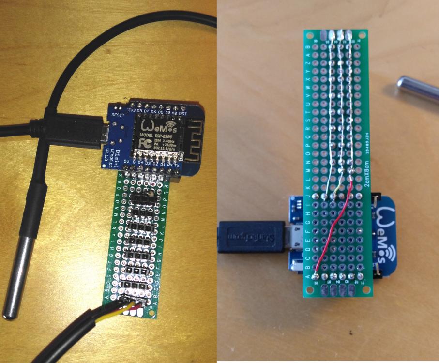
The simple answer is yes, and Wemos even do a standard DHT Pro shield: . I hadn't thought of doing this, but a good option might be to put DHT22s in all of the extract ducts. The DHT22 uses the OW bus at an electrical level but the bus protocol at a S/W level is different. Specifically only one device is supported per OW bus but the Wemos board export 7 I/O pins that can be used to drive separate devices. I terms of my little setup, here is my prototype stage for the logger (total price well under £10 or £15 including half a dozen Chinese DS18B20s): Most of the smarts are on the Wemos Module so the circuit board only contains the wiring to support 8 DS18B20 headers. You just plug your USB into your PC and the DS18B20s into the headers and you are up and running. The power here comes from the USB 5V. There is standard Arduino extension to support this board, but the NodeMCU Lua package typically uses a IDE called ESPlorer, but I use a simplified approach which works for me. In dev mode every time the chip loads a new module it checks back to the mother ship over wifi and if the version is newer than the existing copy then it automatically replaces the file before loading it. This means that I don't use ESPplorer for editing or downloading source. I just do all the editing on my laptop and reset the chip if I want to download the latest copy.
-
That's a good reason to use the encapsulated parts but even if you don't, haven't you missed all of @Nickfromwales extolling of SikaFlex? You can just encapsulate the cable end, soldered joins and tails in a polysilicate or even hot glue and this will pretty effectively waterproof the part alternatively put them in a poly bag. cover this in thermal scrinkwrap sleeve if you are a perfectionist. You don't need a bucket; the centre of a glass will do (to avoid boundary cooling effects) and this is better since it will quickly cool so your sensors will cover the same range together. Beware of rapidly changing temperatures since the individual devices can have varying internal temperature lags, but this isn't an issue in practice if your normal rate of change in less than 1° per hour.
-
The OW protocol uses pull down float high scheme with the clock defined by the master and in the case of receives then there is a ping-pong beat where the slave replies on the.pongs. The transfer is CRCed so any loose connections result in CRC failures and I am not getting any of those. The pull low results in clashes being logically anded and the search protocol uses this plus requesting both the address bits and the not bit to work out common 0s 1s and clash bits to enumerate the devices. Really elegant. I usually use an esp8266 module called the Wemos D1 or pro variant which cost about £3 each from China on a 4 week delivery or £7 direct from the UK. It just plugs into the USB and you program it like an Arduino, so no extra kit is required. I also use the firmware that I help develop: NodeMCU Lua. The big advantage of this is that you only blow the firmware once (except if you are a firmware developer like me). All of the Lua runs out of the on-module file system, so you can update individual modules as needed. I usually do my hardware in three phases: breadboard, prototype and "production". The last two l do using a through hole soldered board to mount hardware modules, connectors and any components. The difference is that the prototype is often just spot hot glued to a mounting board whereas the production model goes in a DIN rail or project box with decent glands etc.. The family supports parasitic power but I don't bother as you need special parts that support it.
-
I've now got 15 cheap Chinese ones. I'll buy some from Darnell and compare them in my test rig. I've been buying the waterproof ones - partly because the probe packaging with lead is far more robust. The cooling cup of water is a good way to check.
-
If anyone is interested, then I can post design and assembly details, esp8266 code or links to it, etc.
-
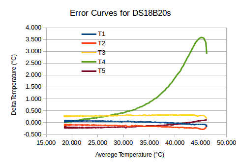
I am just making up my remote sensors for the new house and breadboarded up a 5 ds18b20 one-wire configuration. Just before I wnet off to the hospital, I dropped all waterproof sensors into a glassof hand-hot water and left them to cool. There was one bad outrider so I did an X plot of all five against the average temperature measured by the other four and got this response: I haven't given the curves here but they also show quite difference lag characteristics in responding to higher rates of change. What this tells me is that I need to batch check and calibrate my sensors before using live. They cost pin money in bulk form China, so this is probably well worth while if you want accurate readings or matched sensors. PS. I know that used the Averege, but what the hell. PPS. Another 10 on their way so I should be able to get a properly matched set out of these
-
Can you guarantee that the ventilation into the void will match the airflow through the stove?
-
@Gorlando, if you are going the look at Tony's house Tray and some of his other design details. Also doing the MVHR yourself is really cheap and straightforward if you use a supplier such as BPC (there's quite a few posts on this). Good luck
-
@Trw144, maybe I shouldn't post after drinking with my sons! However it uses sensors, the stove still has roughly a third of its firebox as a radiant panel. As I said, do the radiant heat calculations. It will be very hard to modulate the head output of a stove like this down without significantly dropping the heart temperature, and getting a lot of crud and particulates into the exhaust stream. You still lose at the latent heat of evaporation, so the efficiency will be terribly unless the wood has been air dried for 2 - 3 years. I agreed that this stove mightbe best in its class, but it is the use of this class that I am questioning: too dirty, too inefficient and too much heat output.
-
That might be true for the range of stoves up to and including the one in @Mikey_1980's pic above (and fair disclosure we have a similar one albeit 15 year old technology in our current farmhouse). The problem is that physics is against you if you want to see a nice looking ember heart. For wood to break down all its nasty combustion products, then you need to get the exhaust gas stream up to around 1,000°C. At this point pretty much everything ends up as CO2 and H2O in gaseous form. You can do this by using closed technologies such as a rocket stove. In contrast look at the exposed radiant area in this picture and do the maths -- for a heart of say 0.1× 0.1 m2 radiating at 1,000°C. The radiant heat output is tremendous -- far hotter than an average BReg 2103 house can cope with, let alone a passive house. So you have to use a lot of wood and then let it burn at a far lower temperature -- so as a consequence to you get all of those nasty combustion products up the chimney. I've been thinking about this, and if I really had to heat the house with wood, then I'd use a rocket stove technology, with a short burn (say 1-2 hrs) with the exhaust gasses going through a cob or concrete thermal store. If you can get the exhaust gases cooling down well below 100°C, then you've got a condensing boiler and the efficiency of burning even damp wood goes up to nearer 100%. OK, you will need to fan assist, but that extra 60W of electricity will get the burn efficiency up from ~30% to ~90% so why not? And then thread one of the UFH loops through the same thermal store so that you can control the transfer of the stored heat into the the main UFH. Mind you, this wouldn't help to cool the house during the high summer ;-?