


TerryE
-
Posts
3822 -
Joined
-
Last visited
-
Days Won
30
Everything posted by TerryE
-
Nick as I said this isn't what the regs actually say, and also the IGEM (the Institute of Gas Engineers and Managers) also quite clearly states in its Technical Guidance on The LPG System that: [My italics] So who do I believe: you and Dave, or the professional body responsible for the guidelines? However I've already discussed the safety fastener and maybe I should have declined to show the photo before this was fitted. Ditto using the correct spigot on the gaps pipe and the wisdom of a second anchor near the end of the pipe. I can ask the guy to come back and do this extra work, but I can't criticise him for not fitting an extra valve at the wall if his own standards authority says that it's not necessary. Can I? XXX. Confused from Northampton.
-
@jamiehamy IIRC, 51°C exceeds Bregs. The TMVs aren't fitted with NRVs. But you won't get back flow through a TMV. (Have a read of my latest blog post). Use an O ring or washer. Where I disagree with Nick's approach here (did I just blaspheme, BTW) is the lack of a compression straight on his CW riser. I break all of my copper work into separate sub-assemblies that I can make up on the bench and isolate for pressure testing before putting them into position. e.g. using an end stop instead of the TMV output. I also had my draincocks on tails so these tails can double as the fill points for pressure testing before final assembly. Doing this has three major advantages: No hot soldering in a confined cupboard in a timber framed building. You can test each sub-assembly on the bench (or the floor) before you put it in position. Unless you are Nick, you will find leaks and need to rework. You can flush out any residual flux and crap from the sub-assembly before you put it into position.
-
@oranjeboom, my main concern about that extra 0.02 on the slab U value is that it might entail you having to raise your FFL by 100mm or whatever, so you might loose 10cm of room height, say, for two shades of bugger all difference on your actual heating bills. How you achieve your airtighness (for example) is going to be far more significant in your overall heat balance.
-
Clive's link only describes the BS for flexible connectors and the only one which seems to apply to this is BS3212: 1991 Type 1. Dave your list is unreferenced, and as you say; you aren't a gas engineer. Many of your points might be valid, but how can I confirm this? I've tried doing searches on Google and gone down maybe twenty pages of results, all either not relevant or behind logon walls. Going back to the BRegs, Part J sections 5.19 and 5.20 apply and once we've added a securing chain as you suggest we comply with these. And in fact our gas engineer did tell us that we would need to fit one before the building inspection. Part J section 3.1 also says that all gas works must be a carried out by and certified by a competent person, and this is effectively defined by the person being current with the appropriate certificates and being on the GasSafe register. We also comply with this, though I note Dave's view about the actual competence of my gas engineer. The installation also has to be carried out in compliance with the Gas Safety (Installations and Use) Regulations. I did find the referenced HSE document: Approved Code of Practice and guidance Safe installation and use of gas systems and appliances, Gas Safety (Installation and Use) Regulations 1998 which discusses qualified persons, correct installation, testing, etc., but nowhere does it state that a separate test point is mandatory, for example. And the regulation itself only states that testing must be carried out. I also found a copy of the newer draft 2013 fourth edition does stipulate in guidance 9(1) "Whenever a new gas supply is made available for use in premises, an emergency control should also be provided". And 9(2) states "The emergency control can operate by a key, lever or hand-wheel which should be securely attached to the operating spindle". [My italics]. Yes it does go on to say that if a key or lever is used then it should be a quarter turn, but in the case of a single cylinder surely the hand wheel on the cylinder itself complies with this requirement. I agree that it doesn't in the case of a two cylinder with automated change-over setup, but as I said, we only have a single cylinder. There is a material difference between views of best practice, compliance and non-compliance. I will be more than happy to get the engineer back to do remedial work where we are in fact non-compliant. But interpretations on best practice are quite another issue. As I said the equipment was supplied by one of the main LPG suppliers locally and installed by a qualified engineer. It meets our needs and without firm references, I am not sure what I can go back to him with. I am not the expert here.
-
In our case if the gas runs out in the middle of the night, we'll just use the induction hob until I get around to changing it, so this isn't relevant to us. I am at a total loss as to why you need high pressure hose for ~20 mbar pressure. In the event that the regulator failed catastrophically then the last thing that I'd want is one of my gas burners going up to 1 bar say and blasting a gas flame 20 ft into the kitchen. Far better that the pipe outside fails. The thing about a boat is that it has this gas-tight LPG collector called a hull, and gas leaks in there are a severe safety issue. Maybe we'll have to get Jeremy and Dave hooked up with our local LPG dealer who provided the hose and fittings. As I said guys, can anyone actually point us to where the regulations on this are in writing and publicly accessible, rather than behind some logon wall only accessible to Gas engineers?
-
Taking the second point first; 30 years ago when I last did any gas plumbing I just stuck a monometer (a.k.a. a loop of clear pipe with some red coloured water in it) on the end of the pipe and put a pressure of ~1ft in it (or 20 mBar in new money) and left if for 15 mins to see if I'd lost any pressure. In this case I didn't stand over him whilst he worked, so I didn't see him do the test it, but he did tick the box to say that he'd done it, and he did have a test point to test the copper pipework and the oven for leaks -- the end of the pipe that comes out of the wall. Now that you mention it, I agree with your point about the hose tail. I could get one and the BSP to 15mm adapter from JTM for just over a fiver, but I can't legally fit it, can I? PS: as per Dave's comment below, what does @Nickfromwales, the Lord High Executioner say.?
-
IIRC, its one of those mould plug jobs that came with the cooker.
-
Dunno, but it is double shielded. I'll unplug it and take around the other side. It's only driving the hob sparker.
-
Dave, in a word: yes. I got his name and details off the GasSafe online database. This is one where I didn't even bother to research "how it's done" as I was paying someone to do it the correct way. Jan explained what we were doing to the local dealer and ordered the regulator and bottle from them on their advice. The gas (and LPG) registered engineer, fitted it and provided us with the certificate without comment. So if you think that the Building inspector would have a problem with this installation, then it would be really helpful us if you could be more specific or at least point us to where you can find these details. AFAIK, they aren't readily accessible to the general house builder, because they want you to use a certified professional to do the work. I see that there are potentially two sepearate issues: Compliance and certification; Is the implementation correctly scaled? We've got a backup two-ring gas hob connected to an outside Propane cylinder, not our central heating. Naively, I would think that this apporach is scaled for this; to me, the issue is: does it comply?
-
Just out of interest, why? That is why 0.11 rather than 0.12 or 0.15 even? Remember that the temperature under your slab stays at a pretty constant 9-12°C so the loses are a lot less than you think. -- that's if you have a hard contact slab rather than a ventilated floating block and beam construction where the air circulation under the floor can drop the temperature down to ambient. If you have some large panelled patio doors or the like, then at a U value of ~1 or less if you are lucky -- or bi-fold doors which can often leak like sieve and screw up your air losses, these together can dwarf your delta losses on the slab. My point here is that you nee to regard your house as a total system and invest where it does the most good.
-
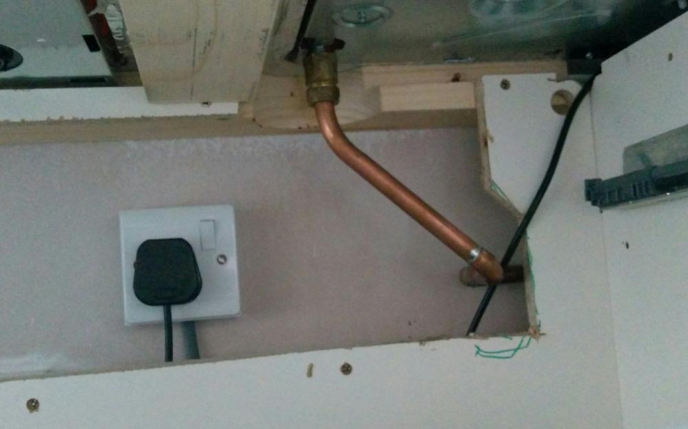
The back of the unit has been cut out to give the induction hob ventilation some open air circulation, but it's behind the drawers in the unit so we didn't attempt to match @Onoff's standards!
-
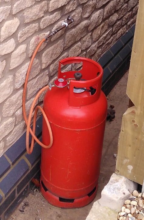
@ProDave we put a 20mm plastic liner pipe through our TF twinwall and out through the brick skin. We sealed that for air tightness. The plumber did the work in two visits. On the first one, he soldered in a 15mm copper pipe with 3 x 90° elbows to run alone the outside wall, 90 bend in through the liner pipe; 90 bend along the back wall and another 90 bend into the back of the unit. (The hole wasn't directly behind the cupboard.) Jan bought the gas bottle and regulator from the local coal / bottled gas merchant in the village. On his second visit (after the worktops were fitted) he dropped the external pipe down to 10mm and fitted the flexible pipe onto this with a jubilee clip. He also needed to add another 90 elbow on the inside to bring the fitting up into the hob connection. All of the pipework fitted behind the line of the unit draws. This sounds lot of work, but the two visits combined were about an hour's work, maybe less. He lives in the next village, so this was a "stop off on the way" infill job for him. Jan or I will take a couple of snaps later.
-
The trouble is that in these "performance measured" times, the inspectors come under pressure to show that they are making a net contribution, that is the sum total of withheld amounts is greater than some gearing on the cost of the office. And this then results in petty reasons for excluding items.
-
There is something that sounds a bit daft here - not with what you say, but with the policy if true. Most of our subcontract work was zero rated. All of our labour isn't charged. Quite a lot is not reclaimable, so our claim really relates to the stuff we've bought. I doubt whether we could credibly lose or slip in an extra £1,000 it we tried, and if what you say is true, then the HMRC are going to spend a lot of effort to make sure that we don't do this. Crazy from a general tax payers viewpoint. I am sure that there are better low hanging fruit to go after.
-
Harveys Water Softeners
TerryE commented on TerryE's blog entry in The House at the Bottom of the Garden
On reflection, I agree about the accumulator. So let's focus on this PRV option. If you thing about it, a PRV bypass can't cause a back flow whatever happens. If you replaced it by a direct through pipe then all this is doing is connecting the input and output of the filter to the same source supply and you'd get no flow, surely? What the PRV does is to open the valve based on the dynamic head in the output chamber of the valve so that at a two bar setting it is fully closed if this dynamic head is 2 bar. With a mains pressure of 3 bar this pressure would be greater than 2 bar if the PD across the filter was less than 1 bar. Let's say we had a demand flow of 40 l /min, say -- as the PD across the filter started to go to more than 1 bar (which is roughly the 30 l/min flow rate), then the bypass PRV would start to open allowing a second direct flow bypass limiting the PD across the filter to 1 bar so roughly 30 l/min would flow through the filter and 10 l/min unfiltered would bypass it, giving a 3:1 mix of filtered to unfiltered water. This is a pretty unusually high rate and might only occur <1% of the time, so the potential scaling risk from this is negligible. However, at least the supply could then cope with these higher flow rates in a graceful manner. OK, the mix thresholds would vary according to the mains pressure, and if this did drop to 2 bar or below then you'd have the filter largely bypassed since the balance would by determined by the PD across the TMV. and if the mains was higher than 3 bar, then the percentage mix would be higher. I don't see our demand really ever getting above the sort of 25-30 l/min level, so I would bother with doing this, but I think that it would be an option for someone with a teenage or young adult family with high shower loads first thing in the morning. -
SunAmp - our alternative to a UVC or TS
TerryE commented on TerryE's blog entry in The House at the Bottom of the Garden
I have just been unpacking my SunAmps. What a neat and well laid out piece of kit! I looks like it belongs in a computer server room, not in a cupboard. -
Harveys Water Softeners
TerryE commented on TerryE's blog entry in The House at the Bottom of the Garden
Jeff, remove it or at least crank it up to 3 bar and fit the flow limiters where you want them. (see my next blog post). -
Harveys Water Softeners
TerryE commented on TerryE's blog entry in The House at the Bottom of the Garden
Here's the schematic of my PRV. The slider which controls the flow from the inlet is set by an equilibrium between dynamic water pressure on the output side acting on the diaphragm and the compression is the adjustment spring. The next figure is the Harvey recommended positioning of the PRV. Since my static pressure is barely 3 bar, the dynamic pressure under load is going to be less than this. The typical dynamic pressure on the PRV inlet side also include the pressure loss through the Harvey, so for anything other than trivia flow rates, the valve will be pretty much fully open. And in fact on our system, I suspect that the PRV will always be open if set at 3 bar or higher. Jeremy is correct that any accumulator on the manifold side will have a standing pressure of around 3 bar, so if the garden is suddenly fully opened then the mains supply side could drop below 3 bar causing a small back flow until the double check valve kicks in. @JSHarris, Jeremy a little Q: what would happen if you replaced the bypass stopcock with a 2 bar PRV? -
Here:
-
And another post one design details. @Nickfromwales, does the pie chart look about right to you?
-
I have been doing the design validation of my plumbing solution partly so I am comfortable that it is feasible and partly to write this up so that others have a model of how to approach this task. The last time that I did anything like this was with my current house where everything apart from taps for drinking water was fed off a (non-potable) header tank in the roof space and the central heating system was a classic 2-pipe (with branches) radiator system fed from a gas boiler. Even though our new house is a generation away in technology: passive-class, airtight to better than 0.6 ACH, low-temperature UFH in slab, pressurised water system using a Hep2O manifold / radial configuration, I still approached the design by refreshing my understanding of pipe dynamics, etc. using such reference works as this excellent intro into pipework calculations: John Heartfield, Water Flowing in Pipes I – The Theory and useful site like the Pipe Pressure Drop Online Calculator. The first is worth a scan if you want to get a handle on some of the sizing issues. However, the figure above shows the pressure losses for the major system components in my Domestic Water System. Note that the pipework losses represent about 1% of the total pressure drop and this value is lost in the noise compared to some of the uncertainties on the larger ticket items. So it really is a waste of time worrying about the pipe losses in a pressurised radial system so long as your follow the following guidelines; this is not where you need to focus your design attention. Configure your pipe layout as a radial system. Try to avoid putting multiple appliances on a single pipe, except where there are strong practical reasons for doing do. For example, our dishwasher is adjacent to our kitchen sink and is a cold fill unit T'ed off the cold to the sink. Plumb all cold and high-flow hot radial piping in 15mm Consider plumbing low-flow hot runs in 10mm, though there is a lot of simplification and little to be lost in going up to 15mm if these runs are short. If at all practical co-locate your manifolds, DHW storage, HW heating, and other directly related equipment in a single service area. This will keep all shared pipe runs short, and associated heat looses small. Properly lag all hot piping up to and including the manifolds. Lag the cold piping as well to avoid condensation. Whilst the pressure drop on common pipework is relative small, it is well worth while plumbing this in 22mm at a minimum. Pipe noise is still a risk so where practical use swept bends rather than tight elbows, and keep track of worst case flow velocities. Keep these under 1 m/s where at all practical and under no circumstances allow them to go above 2 m/s. User full bore valves and fittings where practical to avoid unnecessary flow restrictions. It is worth finding out the the pressure drop vs flow data on all of your system components. You'll typically get these as a set of log-log plots or power curves on linear axes. They are almost invariably approximated by power curve fit and therefore all of the form a.fb where f is the flow rate and a and b are pipe / device-specific constants. So in the case of my calculations, I used the following constants to compute the PD in kPa as a function of flow rate in m/s: Name a b Int Dia 15mm HEP2O 0.00300 1.743 0.013 15mm copper 0.00243 1.742 0.0134 22mm copper 0.00038 1.728 0.0202 25mm MDPE 0.00035 1.748 0.021 28mm copper 0.00011 1.718 0.0262 SunAmp 1.42000 1.810 n/a Softener 0.27600 1.740 n/a PRV 0.04400 2.000 n/a TMV 0.10000 2.000 n/a I then created a test scenario that I wanted to make sure that my system could cope with. IMO, at a minimum this should include two high-flow devices at full open setting running in parallel, but for our design I used what I considered a worst case morning scenario and that was one shower @ 10 l/min and 42°C, one shower @ 8 l/min and 42°C, and the kitchen sink @ 8 l/min 48°C. Note that if you crank the numbers using Dec/Jan water supply temperatures, this comes out at an equivalent instantaneous heat demand of 67 kW, and given that combi-boilers top out at 40 kWhr, this is well over 50% more that the largest combi- boiler could deliver. It's then just a case of doing the temperature blend and flow-rate calculations and cranking the numbers in a spreadsheet. On my first pass through, it was very clear that attempting to satisfy this short of flow rate through a single SunAmp was just beyond its rate capacity, but luckily we had already two configured in parallel. Even so, the parallelled SunAmps account for ~ 0.55 bar pressure drop, along with the DHW TMV. The water softener accounts for 0.8 bar and the Honeywell pressure regulator 0.3 bar. The difference in pressure drop on the 3 pipe runs (all being ~1% of the total) is negligible, but since the total is ~2.25 bar and the actual head is 3 bar, we have ample headroom to sustain this scenario. (Actually one of the showers is on the second floor, so in this case we lose nearly another half bar getting the water up there.) If the net figures are negative then we aren't going to achieve this flow rate and we will be system limited. But they are all positive, so we are OK, and this means that the taps or the various flow restrictors are going to have to do their work to limit the flow. So what could I do if I wasn't achieving the desired flow rates? Basically the answer either to revise my expectation downward (after all my current house design can just about deliver half of this); to increase unit capacity by upgrading in some how (e.g. in my case doubling up on the SunAmps), or to think out of the box. The biggest single hit here is the water softener, and in fact I introduced this fairly late in the design process when I realised that having one is pretty much essential with my level of water hardness, but that's life, I guess.
-
Harveys Water Softeners
TerryE commented on TerryE's blog entry in The House at the Bottom of the Garden
Jeremy, thanks for the feedback. Anglian Water pump the supply where we live and keep it to just a tad over 3 bar. This sort of drop is liveable with for most scenarios, and it works for us, but it is still big enough that self-builders need to be aware of this in planning their systems. I'll discuss this in my next blog post. -
This is a poke to J, J, and N @jack@JSHarris@Nickfromwalesjust to read and have a sanity check on my blog post on Harveys Water Softeners and let me know if I've said anything daft. Ta. Terry
-
If you have a Combi boiler, or SunAmp, or pretty much any device with a built in Plate Heat Exchanger (PHE) and live in any region which has hard water (about 80% the UK population), then you will need a water softener if you want any decent life out of your plumbing installation. As far as I can see you are down to one of two options for a direct plumbing solution: the UK Harvey twin tank system and the US Kinetico range. All of the rest are niche suppliers, IMO. The Harvey system seems to be viewed as the best in terms of performance and running cost; and a few of the others on the forum use one and have recommended it, so we went with this choice. The basic Harveys internals are boxed and rebadged by a number of suppliers: Harveys, TwinTec, Fountain Softeners, but the versions currently shipping are one of four standard Harveys models under the hood: 500, 750, 1000, 1400 (which relates to the volume of water in litres per flush). And these have a guideline maximum PPM of 320K/<model no>, so the 750 is advised for a maximum of ~ 430 ppm water hardness. This is the one that we have. Each flush on the Harvey is 17l, so the 750 flushes 17/750 = 2¼% of the water (which incidentally is under the 4% threshold on the Water Usage calculation required for Part G approval). So in our household we use ~250l /day and so will do 10 flushes / month @300g salt per flush or 36 Kg of salt p.a. 12 × 8 Kg block salt costs £72, so our expected annual salt cost is approximately £27. A lot cheaper than some alternatives, and this has to be offset against reductions in soap and other consumables. Now to my big bitch. I was researching the performance data of the Harveys Softene and trying to find simple performance data on the typical pressure drop vs flow. Talk about shifty and evasive. You can't find this anywhere on the Harveys site; ditto the TwinTec, and the Fountain Softeners site. I also tried an email to my named contact at the last, but got no reply one this. There's lots of qualitative hand-waving in YouTube videos and promotional material, including from Mr Harvey himself -- all to the effect that the pressure drop is not that bad / a lot better than the competitors, etc. Calculating this pressure drop vs flow graph isn't difficult. These curves all approximate well to a power curve, so the tester will normally takes a few PD : flow measurements over the working range of the appliance, plot them on a loglog plot; fit a straight line; and then invert this back to the power curve. OK, in the case of a water softener, the actual value might vary over the flush cycle so you might need to put in a upper / lower band on this curve, but all of this naaa-di-naa-daa sounds like they are hiding something to me. So after a bit of Google searching I happened across a link to a PDF on a website run by a landlady in Reading (how Google found this, I have no idea). This was the standard 4 page installation guide that is most of the sites, but plus a fifth "Technical Data" page: which includes this plot. What this shows is that at a 30 l/min flow rate you are loosing 1 bar through the softener, This equates to a couple of showers going at the same time as the kitchen sink. However if you have power showers or the like, then by 45 l /min you are at 2 bar and with the other system loses, your water system will begin to struggle if you only have a 3 bar supply. Of course if you have an accumulator, then this will be positioned on the house side of the filter, so this will greatly mitigate this limit.
-
Tiling behind Wall mounted toilets
TerryE replied to JanetE's topic in Bathrooms, Ensuites & Wetrooms
The ones we got from Megabad came with a 110 adaptor.

