


TerryE
-
Posts
3822 -
Joined
-
Last visited
-
Days Won
30
Everything posted by TerryE
-
Why don't come over one w/e and we can chat about this? Or I visit Roade.
-
Vijay, one thing to be aware of is the height of the water table and the soil type. 200mm hardcore on its own won't take heavy lorries if the underlying soil liquifies. This will a spread the top load and help to minimise wheel damage but you need something solid underneath. We have a firm clay 2 miles down the road. This will take really heavy loads if it is drained and free from surface water, but once wet, it looks like the brick clay in Ed's barrow. You might need to put in land drainage either side of the line that the lorries will use, and drain / pump this. OR used a lot more temporary subbase.
-
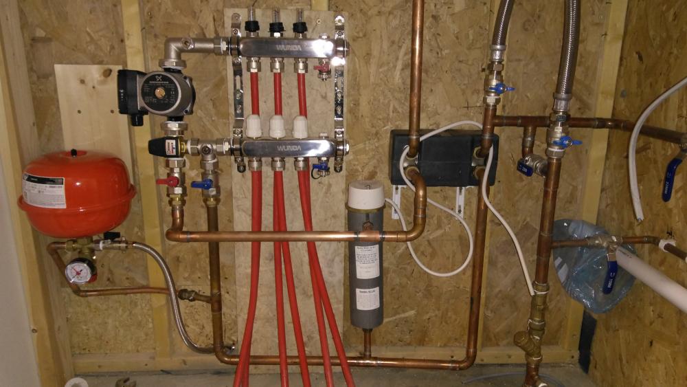
@joe90, I used the ESBE valve because in my system I don't generate enough power to need a valve, so I chose the simplest. But it's the Gunfos pump.
-
When did you buy your manifold. I've got the "premium manifold" which is the one that they are selling now on the Wunda website. This uses one of the port pairs for the two filler / drains. Is your manifold the previous generation? If looks as if the filler / drains on your are for left hand mounting and isn't listed on the website. Which pumpset have you got? Is it the one which can be mounted on either side? If so then one option would be to reverse the flow direction, that is have the pumpset on the right. Mine is designed for left hand mounting only.
-
So here is the UFH setup. There's one fill line missing; I was just about to fit it but Jan ordered me in for dinner. The Wllis heater is in between the UFH and the PHE.
-
Can't find the right stopcock (copper to mdpe)
TerryE replied to ProDave's topic in General Plumbing
Anglian mandated that our internal trench and pipe from the boundary to the house was at 750mm depth, and then the gang that connected us up put the main in the road at around 600 coming up to maybe 400mm at the water meter for the pipe to dive back down to 750mm in our trench. A bit of a farce really. -
Can't find the right stopcock (copper to mdpe)
TerryE replied to ProDave's topic in General Plumbing
@PeterStarck, I think that you will find that it is Water Regs as much as Buiding Regs. Certainly Anglian require you to have a stopcock (that is a proper stopcock) and DCV and draincock on all direct connections to the water supply. So If the outside tape is on a spur before the supply enters the house then it must essentially be configured as a standpipe (search for standpipe to see the thread on this). If it is on a spur between the main stockcock and the DCV then it must be protected by a DCV If it is on a spur after the main stockcock and then it should still be protected by a DCV. In these last two cases AFAIK, it is up to you what type of isolation valve you need to fit if any. -
Can't find the right stopcock (copper to mdpe)
TerryE replied to ProDave's topic in General Plumbing
Dave, IMO, the modern ball and socket valves are milled and polished to such a tolerance that they really are a trouble free way of ensuring on/off flow control. -
Can't find the right stopcock (copper to mdpe)
TerryE replied to ProDave's topic in General Plumbing
Dave, just out of interest can you explain your rationale for wanting a traditional stopcock? It's just that with the exception of the main 25 MDPE to 22mm stopcock, I've gone down the lever operated full bore ball valve route for all of my internal water valves: easy to operate with a 90° twist and no impediment to water flow when open. OK, I've stuck with a boring WRAS-approved stopcock for the main entry, but to me the ball-valve approach is just so much easier. Surely the internal valve to the external taps is just another valve? The main reason that I suggested the push fit post is that I couldn't find the EF or compression equivalent. I also prefer solder joints for main lines, with the odd compression to allow you Brad it into sub-assemblies for maintenance, but the push fit stuff, especially the Pegler Texture Classic look very good. -
Can't find the right stopcock (copper to mdpe)
TerryE replied to ProDave's topic in General Plumbing
So why not try the JG Speedfit MDPE PE - Copper Coupler 20 x 15mm and a 15/15 ball valve? -
Can't find the right stopcock (copper to mdpe)
TerryE replied to ProDave's topic in General Plumbing
Who says you need to use a stopcock? What's with a full bore 15mm ball valve + lever where you T off the rising main? Then convert the 15mm to 20mm MDPE with a standard insert like this. -
All potable water plumbing pressure tested today. TaDa!! I've got about 30cm (of the 2m coil lead-free solder that I bought) left so it's touch and go as to whether I will have enough to do the last UFH copper loop, so I might still have to do some lead soldering, but this is for the UFH so that's allowed.
-
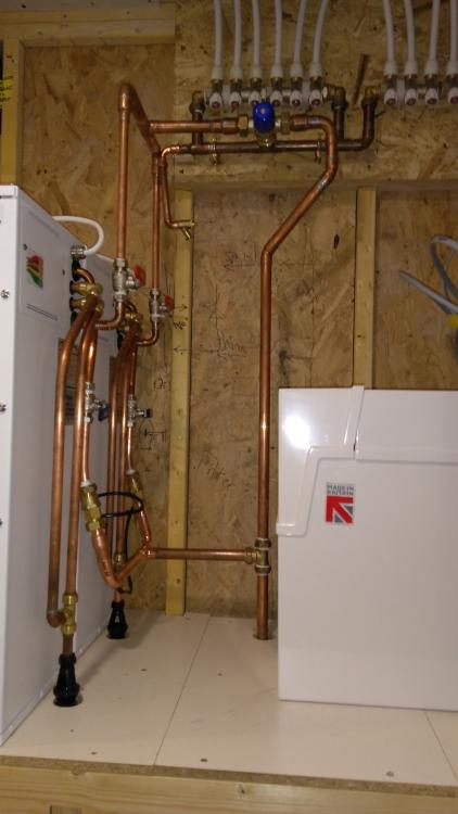
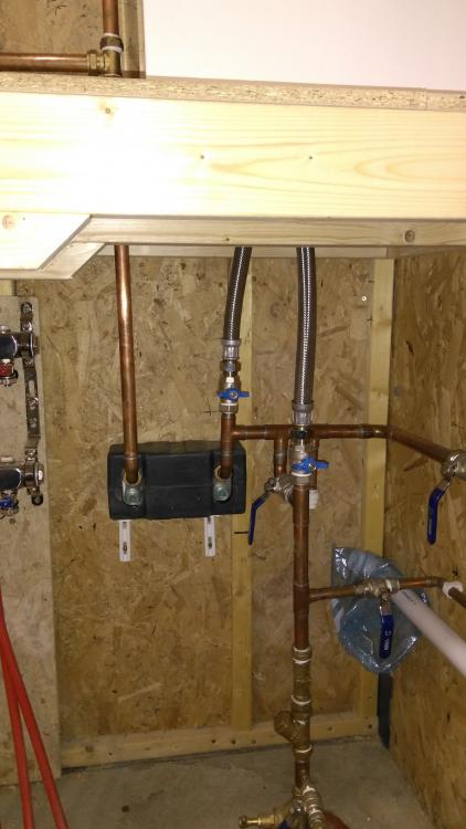
Potable water all plumbed up (apart from one pipe section which has been cut to length and fitted but not as yet soldered up). Time for a glass of wine intervened. To give you a sense of the size of the water services area, the two SunAmps on the left are hard against the LH wall and the Harvey water softener on the right hard against the right one. You will see from the picture below that I've still got to add the loop between the manifolds, Willis Heater and PHE, plus the expansion vessel / fill system for the UFH, but that's tomorrow's job. I've designed the connections to the SunAmps so the two SunAmp units can be isolated, disconnected and removed or swapped, so I can always take one out for maintenance. @Alphonsox, also note the two flow meters on the feeds into the SunaAmps. This flow and the temperature rise will together tell me how much (and when) I am using DHW. I've also gone to great lengths to minimise or remove any unnecessary bends on the main water paths. The manifolds on the left pic are the DHW so I will be boxing these in.
-
Help me deal with a neighbour!
TerryE replied to hmpmarketing's topic in General Self Build & DIY Discussion
Yup, I wondered about this. IMO, the local Highways Department would never do (or approve) allocating parking on a public footpath. I strongly suspect that the originator of the reserved parking area was your neighbour himself. It's about as valid as you painting "NO PARKING" over it. -
WH toilet frame and MBC stud frames
TerryE replied to ryder72's topic in Bathrooms, Ensuites & Wetrooms
@ryder72, I think that Nick has explained more constructively what I was trying to say: dropping from 210 PIR to 140 PIR for the 1m2 or so of the Gerberit is going to make bugger all difference to your overall heat losses, but is going to add a useful 8cm or so on one wall of your bathroom / en-suite. -
WH toilet frame and MBC stud frames
TerryE replied to ryder72's topic in Bathrooms, Ensuites & Wetrooms
If your over-engineering isn't going to lose you living space, then it doesn't really matter, does it?. The front frame (with the covering plasterboard) will be rigid and strong enough. The only possible flex will be in the z direction -- that is normal to the wall surface and timber fixings between the inner and MBC frames will remove this. If you do the heat loss calcs then there's is no material reason why the inner plasterboard surface needs to be more than 120 inside the /mbc frame -- that is 50mm inside the 70mm PIR inner. If you cut the Gerberit frame into the 70mm PIR inner then you might lose an exta few W heat loses but you've gained extra living space by doing so. Either you understand my point, or I am not explaining it well. Sorry. Perhaps one of the other member with an MBC frame such as @jack or @JSHarris or @Calvinmiddle should contribute their PoV, becaue I might just be in the minority here . -
WH toilet frame and MBC stud frames
TerryE replied to ryder72's topic in Bathrooms, Ensuites & Wetrooms
As I said KISS. Your plumber is over engineering this and you are losing living space for no good reason. I'd bolt the 12cm frame directly to the underlying MBC frame through the PIR. Why on earth not? -
Seriously Nick, I was going to put in a 5 or 6 bar PRelV until I realised that the Sunamps each had one in that would be easy to replace so why bother? The installation guide for the Harvey explicitly states that the 3 bar PRedV should be fitted after the softener and that a 5 bar PRedV should only be fitted n the supply side if the supply rises above 5 bar. The Harvey is tested to 6 bar, so the risk if Anglian decides to double the pressure is that the SunAmps PRVs go. Oh, yes and all sorts of leaks will spring up throughout the village supply which has never been stressed to this level and ditto most of the houses in the village. It's a risk that I'll accept.
-
The SunAmps have 6 bar PRelVs in them that look very much like your link and as I said, I've taken the main system up to 7 bar.
-
Nah, I'll live dangerously and put in a pressure transducer as Peter pointed at and rethink if I start getting supply readings over 4 bar.
-
WH toilet frame and MBC stud frames
TerryE replied to ryder72's topic in Bathrooms, Ensuites & Wetrooms
Keep it simple stupid. Timber fixing the studs to the 140mm studs through the top PIR will do bugger all in terms of compromising the thermal characteristics and is nice and simple -- so I would vote for the MBC suggestion. One thing that I would question is the 38 mm. If you are using the Geberit-style cisterns then they need 100mm depth though I think that you can get shallower ones. I didn't think that you'd want to start cutting these into the 70mm PIR layer but one reflection, I'd consider doing this if it were my house. So I would just fix the Wall Hung frame direct to the underlying MBC suggests. -
Sorry but this statement doesn't seem consistent with the physics. Inefficiency could be defined as the percentage of heat energy lost out of the system, and the system here is the house interior. There are two main sources of heat loss: heat carried in the gas stream, and (in the case of wood) latent heat of evaporation. Wood burns inefficiently because it has a high moisture content and this water has to be boiled off, and the remaining lignin and cellose has a reasonable low energy density, so unless wood has been air dried for at least 2 or 3 years then most if the energy goes into boiling its water content. This isn't the same for coal or coke. The other thing is if the chimney is internal to the house, then a lot of the heat is lost inside the house and goes to heat the upper storey. A decent sealed stove only allows enough air through to oxydise the coal and I know by putting my hand in the gas stream coming out of the chimney, in our farmhouse that it ain't that hot. Maybe 40°C. So I would have expected the system efficiency of a decent multifuel stove burning coal or smokeless to be nearer the 80% end. The carbon contribution is a completely different matter?
-
I've got quite a few BSP fittings in my system. Getting my head around these isn't straight forward. Hence this topic just to have a sanity check with @Nickfromwales et all, and for others new to this confusion. In Europe BSP junctions have two flavours: Tapered or BSPT (also known as "Iron" fittings since these are commonly used on iron pipework). Here the taper allows the seal to be made on the threaded section. Parallel or BSPP.. Here the threads do not be themselves seal the joint but instead pull the male and female parts together. The seal is by a washer or O ring at one end of the fitting. Most if not all of my fittings use BSPP and therefore need washers or O rings. Even so it is still not simple as on any fitting there is an inner male and outer female part and BSPP fittings do not have a consistent approach to whether the seal is at the female end or the male one. Taps have the seal at the end of the male end and the female is also male in that it has an inner guide that slots inside the male. Fittings like my Hep2O manifolds have the seal at the female end and in fact the male end doesn't even have a decent face to put an O ring against it you wanted to. Fittings like my PHE and TMV have the seal at the end of the male end, but the inside diameter won't accept a tap connector, so I need a female fitting with a flat plate inner face and matching washer. Tap washers will fit but the seem unnecessarily narrow. In the case of my PHE for example, I want to turn a 22 mm pipe into a ½" BSPP male. I originally planned to use a ½" to 15mm tap elbow with a 15 to 22 EF convertor, but this involves (1) cutting off the inner flange and filing flat, and (2) having a 12mm inner diameter on the turn. A better solution is a straight ½" to 22mm coupler and a 22 EF street bend, as this preserves the inner diameter of the PHE fitting as the narrowest restriction. So any words of wisdom on this mess? Any advice on best place to approach this, get fittings / washers / o rings? One last comment here is that I came across a recommendation to use liquid PTFE if you want a good seal. Is this a good idea?
-
You have to get the control system right. Do a design review here if you are uncertain.
-
Whilst I agree with Pete's comment and used planings for our temporary (and which later became our permanent base for our driveway), there is one caveat: if you are going to remove it later, this might be quite expensive because it won't be treated as hardcore and it will have to go a registered dump if you can't find someone who will take it.


