


John Carroll
-
Posts
577 -
Joined
-
Last visited
-
Days Won
3
Everything posted by John Carroll
-
If, which it is, the pump is pumping over on start up, then its more than likely that its doing the same on stopping so will eventually draw in air from the vent, your pump (I have the pump curves) will only develop a head of 1M on speed1, a bit surprising that that head is sufficient to heat all your rads, but shouldn't in itself cause that pump over except it starts up at full speed (6M) and then ramps down which I wouldn't expect it to, you said it uses a bit more power than the Grundfos, does it display this power (W), what is the power wherever you are getting it. The pump over often points to a blocked or partially blocked cold feed where it joins the flow pipe, in one of your posts above you show the cold feed & the vent where they are teed into the flow pipe, is the flow from left to right or right to left?. What was the pump power and where did you get that from?.
-
If you remove the vent then the now combined feed & vent must be 22mm with no isol. valve. What is the height roughly from the F&E cistern water level to the pump and what is the pump set to, speed 1,2or3?. If that height is greater than the pump head, then the pump suction could possibly be running at a negative head and eventually pulling air in, for example if the distance is say 3M and the pump head is 4M, then the pump might be running with a negative suction head of 1M. Anyway try the glass test and give a rough idea of the height and pump speed. Did you have a gas or oil fired boiler previous to the change?
-
With the pump running, hold a "glass" of water with the end of the vent immersed in it and see does the level start falling.
-
Looking at the R290 properties, 5.0Bar = 9C & 8.3bar = 24C. And 3.0bar = -6C & 12.54bar = 39.5C. The pressures in the attachment look like absolute, so add 1.0 to your pressures when (if) reading them. Refrigerant R290 Properties.pdf
-
Vaillant EcoTec Plus 630 dT
John Carroll replied to John Carroll's topic in Boilers & Hot Water Tanks
Its not my boiler I have a oil fired boiler. It was running (CH only for first 2 tests) at a modulation level of 4, I think it goes to 5 max?, 16 rads, all fully open so even with flow/return of 64C/44C, dT 20C will still give a rad(s) output of 60% so no way is this boiler output down to minimum, a dT of 20C with a target temp of 64C gives a return of 44C and a nice bit of condensing. if the boiler can achieve this dT of 20C then far easier than spending hours balancing rads to achieve it?, I would say its a excellent feature if it works. -
The boiler flow/return dT can be set in the above by changing a few parameters to set the dT to between 10C and 20C, see attachment. However this does not seem to work for someone I know, it worked to a fashion on CH only but not in HW mode (this isn't a big deal though) The dT was set to its max, 20C in all the examples, below. The best result (briefly) was a dT of 17C with flow/return temps of 64C/47C, pump speed 58%, next best gave 64C/50C, dT 14C, pump speed 64%, and on HW (cylinder), 64C/60C, dT 4C, pump speed 80%. Can someone throw any light on this or if they have a EcoTec Plus try these parametrs to see wht results they get, this boiler is just 1 year old. D.170 is set to 3, which is temperature spread control or dT. Vaillant EcoTec Plus 630 dT.docx
-
Clicking noise from UFH manifold when it fires up
John Carroll replied to thefoxesmaltings's topic in Underfloor Heating
Do these actuators act like a TRV with a wax/liquid filled capsule?, I thought the might just position the valve based on the signals from from the controller which then drives the motorized actuator. -
This may be of some help?. HW Priority Diagram.pdf
-
Ideally,on the feed downstream of the expansion relief valve, would need a T with a isolating valve and the PG on the end of the T.
-
Get a pressure gauge installed.
-
Grant Vortex Oil Fired Boiler micro firing?
John Carroll replied to John Carroll's topic in Boilers & Hot Water Tanks
It was found that the MPV would go to and stay in mid position when CH only was selected, a replacement new Honeywell ST9400C programmer appears to have solved the problems. -
Grant Vortex Oil Fired Boiler micro firing?
John Carroll replied to John Carroll's topic in Boilers & Hot Water Tanks
Not sure why the 2(N) etc but I'm quite happy that what was tested (not by me, but suggested by me) was 1 to N, 4 to N, & 7 to N. The measurement 1 to N was taken from Ter 1 on the boiler terminal Block to Ter 2 (N) on the boiler terminal block which I would think should show any pulsing? I am only trying to assist some one else, my 19 year old Firebird with its Riello G5X burner is faultless and has never tripped even once. Thanks for your help, I will suggest testing between 10 & 2 on the wiring centre. -
Grant Vortex Oil Fired Boiler micro firing?
John Carroll replied to John Carroll's topic in Boilers & Hot Water Tanks
Tests so far, not mine or not my boiler Can you or someone identify each terminal connection, especially the switched live and the permanent live on the boiler terminal Block drawing, attached. Terminal 1 appears to be connected to the MPV? yet the reading is constant for all three positions, if the orange wire is pulsing (CH position only) then the M/meter isn'n picking it up. HW+CH (boiler hunting) 2(N) - 1 240v constant 2(N) - 4 all over the place. Probably about 58. is most consistent reading 2(N) - 7 240 through cycles. Shows OL for split sec when switching back on HW only (no problems) 2(N) - 1 240v constant 2(N) - 4 all over the place 2(N) - 7 random figures as low as 6v and up to 180v CH only (no problems) 2(N) - 1 240v constant 2(N) - 4 all over the place 2(N) - 7 240v constant No room stat just TRV on rads.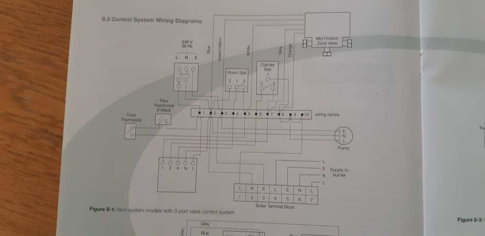
-
You seem happy enough now, wonder why such a exotic Baxi combination valve set is required and the Caleffi was "wrong". I think the procedure for the bubble is to ensure that its not being compressed until the last ~ 25% of the cylinder vol as some schematics show the dip pipe bottom almost level with (or a little below) the TPRV, that's why I showed the 100% air bubble and the 25% air bubble, the total vol of water after reheating with the 25% bubble is 200L and is only 160L with te 100% bubble but IMO the available HW is still almost identical because once cold water rises up to the level of the dip pipe bottom then thats the effective HW available, some other makes like OSO have a removable dip pipe to give you that lost vol of HW if a EV is installed, looks to me that you could lose ~ 20/25% of the cylinder vol with the Megaflo.
-
With a ASHP or weather compensation one should try and keep the dT as low as possible to achieve the lowest possible flow temperatures at any required output, I generally use a dT of 5C, but I just use my attached calcs to give any combination required. Radiator Output crispy.xlsx
-
Grant Vortex Oil Fired Boiler micro firing?
John Carroll replied to John Carroll's topic in Boilers & Hot Water Tanks
Something like that but the boiler run signal is still the same with the valve in mid position? so the hunting valve still makes the most sense to me. -
Grant Vortex Oil Fired Boiler micro firing?
John Carroll replied to John Carroll's topic in Boilers & Hot Water Tanks
The work of the Devil allright but a most ingenious device. The MPV hunting was/is my chief culprit too but judging on the results I got when interrupting the supply to mine then doesn't match what the Grant is doing, apparently stopping/starting every couple of seconds, I'd be surprised though if it should behave much differently to my 18 year old vetern in that regard, more tests are being carried out tomorrow, will inform. -
Well, if the pressure is exceeding 3.9bar after a reheat which I think it is from what you are observing, the only other explanation is that the new PRV is creeping/leaking past say overnight, can you post a photo of any details from any labels etc. Re re doing the bubble, if the bubble formed while just filling the cylinder then I reckon the final pressure would only be 3.2bar, if re bubbked per instru tions, pressure around 4.3bar but both ev and cylinder pressure will equalize so I don't see any great benefit in re doing it but why not? If you have a single lever mixer and leave it in mid position the PG on the cold PRV might tell something overnight or after a few hours, have you noticed what it reads any time the hot and cold havn't been used for awhile? Attached is a handy calc sheet I made decades ago and added the bubble calcs a few years ago, it may be of interest. Expansion Vessel Calculation Steve.xlsx
-
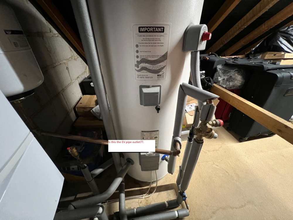
I know that the pressure is subjective (my kingdom for a pressure gauge) but IF the EVs pre charge pressure was checked/adjusted to 3.0bar gauge then the final pressure after reheating the full contents to 60C will be only be 3.93bar, hardly noticeable, one would think, when a hot tap is opened, if the EV precharge pressure wasn't checked or charged incorrectly to 1.0bar, then that final pressure will be 5.43bar, in either case the pressure will fall to 3.0bar when the expanded vol of 3.4L has flowed from the hot tap, in the very unlikely event that the precharge pressure is only 0.6bar then the final pressure will be 6.58bar. Re the EV pipe outlet, just to be absolutely clear, is it teed in where I show it in the photo?, if so, quite correct, if not, and teed in before the combination valve (effectively, no EV in the system) then the expansion will still be taken up by the Megaflo's bubble which will still be there if the dip pipe hasn't been removed, I reckon that the final pressure (with no EV) will then be 4.28bar after expansion, not bad until the bubble disappears, if the EV is installed correctly and the bubble exists then there could be some shunting between the EV and the cylinder which could conceivably cause noise again eventually. Theres definitely something not quite right IMO because the final pressure with both the EV and the air bubble should only be ~ 3.4bar after expansion, certainly not noticeable? The other possibility for the high pressure is that the balanced cold isnt, it may be at a higher pressure and leaking through a mixer and pressurizing the cylinder.
-
Grant Vortex Oil Fired Boiler micro firing?
John Carroll replied to John Carroll's topic in Boilers & Hot Water Tanks
Don't know what type of burner but no modulation, my Firebird will do the full purge as fast as I can switch it on/off, i have experienced this micro firing only a few times in 18 years while the boiler was running normally but cannot see how running with CH&HW should affect this Grant except the violtage is being pulled down or something like that. -
Thermostatic mixing valve on hot water cylinder
John Carroll replied to Little Clanger's topic in Boilers & Hot Water Tanks
No, IMO, because the immersion elements are inserted horizontally (presumably) then they will heat the water from the bottom up. If you drew off say 20L of HW from a fully heated cylinder then the element will only reheat this 20L to 60/65C. -
Grant Vortex Oil Fired Boiler micro firing?
John Carroll posted a topic in Boilers & Hot Water Tanks
Came across this problem on another site, someone may have words of wisdom. The system is Y plan with a MPV, if either CH or HW is selected then the boiler cycles normally, if both CH and HW are selected, then the burner switches on/off every few seconds until CH or HW is again selected, it seems to have all the symptoms of micro firing. I thought it could possibly be due to the MPV hunting in its mid position interrupting the power to the boiler but a few tests on my own Firebird (S plan) seems to rule this out, when I interrupt the power to the burner for a second or two, the burner cuts out then does its 12 sec (pre) purge and refires, if I interrupt the power when its say 6 sec into its purge then it again just does a full 12 sec purge before refiring, if I interrupt the power immediately after refiring but before the extra 5 sec for flame detection has elapsed, it does exactly the same, a full 12 sec purge and refire, all as expected really?. I have suggested selecting HW only on, then manually latching the valve in mid position to see what happens. -
Where is the EV connected into the system?, it looks to me to be teed in to the cold feed after the combination set which is correct?.
-
I allways wonder why a PG is rarely if ever installed either on the cylinder or even the PRV, which would be very useful for trouble shooting, the EV is normally sized to 10% of the cylinder capacity so the final pressure after a full reheat to 65C should still only be 3.9bar, unlikely to cause noise while releasing the expanded volume of 3 to 5 litres while falling to 3.0bar, a leaking/passing PRV could easily increase the filling pressure to 4.2bar overnight, the final pressure will then be 5.8bar, far more likely, even though it shouldn't, to cause noise when a hot tap is opened, I wonder are these PRVs drop tight.
-
Looking at that photo again, looks like that pipe is (correctly) the T in from the expansion vessel.


