John Carroll
-
Posts
577 -
Joined
-
Last visited
-
Days Won
3
Everything posted by John Carroll
-
boiler behaviour,please let me know your thoughts.
John Carroll replied to Post and beam's topic in Boilers & Hot Water Tanks
Found this in one of the MIs so if this is the 2965 sensor then it looks like it must reach 120C to operate and doesn't reset until it falls to 80C.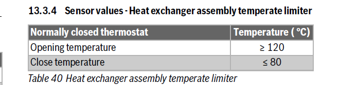
-
boiler behaviour,please let me know your thoughts.
John Carroll replied to Post and beam's topic in Boilers & Hot Water Tanks
I spoke to WB technical and they agreed that the "2965" sensor should not reach 88C when the flow temperature reaches 90C or more, the person I spoke to wasn't aware that a low flow as such should trigger it, he suggested that WB technical are again contacted. -
boiler behaviour,please let me know your thoughts.
John Carroll replied to Post and beam's topic in Boilers & Hot Water Tanks
I would take careful note of what SimonD said in one of his posts before ......"max boiler temp of 82C it would sometimes get to over 90C as the cylinder reached target temp and the diverter valve closed and the system then relied on the bypass only for flow. But never did the boiler block as such, just tripped the burner as would be expected." -
boiler behaviour,please let me know your thoughts.
John Carroll replied to Post and beam's topic in Boilers & Hot Water Tanks
Interesting, looking at their reply again they said the heat exchanger temperature and not the flow temperature so there could be a significent difference in these depending on where the sensor is attached, could be something as simple as a faulty or badly attached blocking sensor? Its a wonder the experienced WB engineer wasn't aware of this sensor's setting and location, i would chase them a bit further especially since this fault has been there since early on. -
boiler behaviour,please let me know your thoughts.
John Carroll replied to Post and beam's topic in Boilers & Hot Water Tanks
I popped a email to WB, they inform that..... "The blocking code 2965 is generated when the heat exchanger temperature is greater than 88°C." So irrespective of TRV settings or whatever, once the heat demand is less than the boiler's minimum output then if the target flow temperature is set to 82C then it is almost inevitable that the temperature will reach 88C since all gas boilers don't trip the burner until the flow temperature reaches target temp+ (at least) 5C. This setting is far too close to the WB approved max flow temperature setting of 82C. I will now pose the question to them of whether there is a delay in clearing that alarm if still up on c/o to DHW. -
boiler behaviour,please let me know your thoughts.
John Carroll replied to Post and beam's topic in Boilers & Hot Water Tanks
If the boiler flow temperature can be noted at when in DHW mode then this will give a good clue to the performance of the primary & secondary HEXs even though the blocking is apparently occuring during CH operation, I know I've repeated this more than once but if 2965 is just triggered by a the flow sensor, or maybe a a separate primary HEX sensor, it would be nice to know its setting. I posted these readings earlier from a 30kw WB CDI boiler which may give some clue, that boiler seemed to provide all sorts of info, don't know if this boiler has even got a return temperature probe. Fouled PHEX, (DHW setpoint 55C). DHW flowrate: 9.2LPM. DHW Temperature: 44.5C. Boiler flowtemp: 71.5C. Boiler output 16.4kw Mains Temp:19.0C NEW PHEX, (DHW setpoint 55C). DHW flowrate: 10.0LPM. DHW Temperature: 54.5C. Boiler flowtemp: 64.5C. Boiler output 24.1kw. Mains Temp:19.6C. -
boiler behaviour,please let me know your thoughts.
John Carroll replied to Post and beam's topic in Boilers & Hot Water Tanks
Back to reality, I would love to know what temperature triggers this 2965. -
boiler behaviour,please let me know your thoughts.
John Carroll replied to Post and beam's topic in Boilers & Hot Water Tanks
It was that darn 2965 that overheated the brakes on me but I had to blame the mechanic, Fangio had the same problem in 1956 but he still won. -
boiler behaviour,please let me know your thoughts.
John Carroll replied to Post and beam's topic in Boilers & Hot Water Tanks
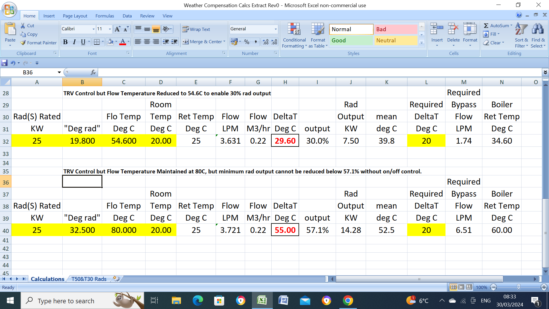
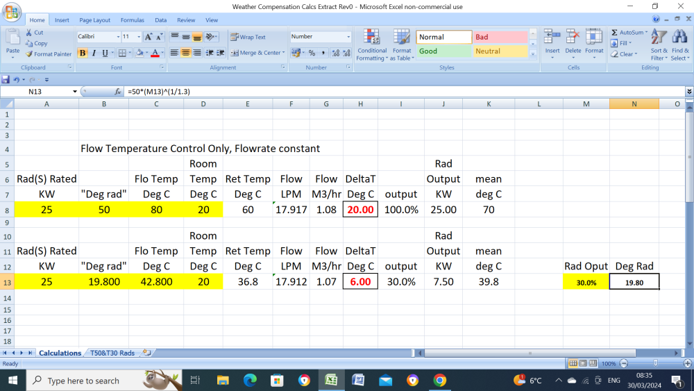
Hi, Max Verstappen here, I do know quite a lot about radiators since they play a very important part in keeping my engines cool but also know how the rads work in my modest 4 bed house in Belgium. All boiler manufacturers use a dT of 20C (and have a settable flow temperature of 80C/85C) to calculate the max flowrate through their HEX and still allow sufficient pump head to circulate through the system rads etc without having to install a LLH or the like. Bearing that in mind a T50 rad must have a flow temperature of 80C with this 20C dT to give its rated output, the rad full output may only be required at a OAT of say -7C, the rad output requirement then reduces with increasing OAT so the rad flow temperature can be reduced to give this output, this can also be done by installing TRVs but these need careful monitoring as they can quickly run out of control at high flow temperature and also require a boiler internal or external by pass or both, it can be easily seen below the effect of not reducing the flow temperature and the very big effect on flowrates as was pointed out above.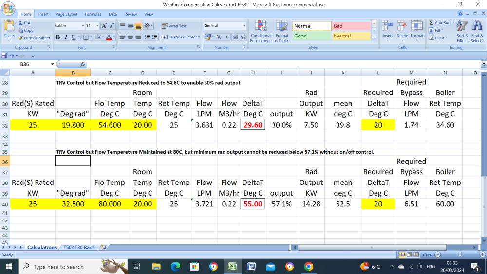
-
boiler behaviour,please let me know your thoughts.
John Carroll replied to Post and beam's topic in Boilers & Hot Water Tanks
Its truly amazing that WB havn't divulged (or have they?) what temperature that code 2965 operates at as in my IMO its the key to the whole discussion/argument, if it operates at say 88C then because you can "legally" set the flow temperature to 82C and the burner won't trip until the flow temp reaches 87C/88C then clearly a WB problem but if it operates at say 95C then its a circulation problem (for whatever reason) when the boiler goes to either recycle or pump overrun to cool the boiler HEX, then not a WB problem. Maybe a clue in this whatever possible means.
-
aroTHerm seem to have a strange way of sizing their units, I generally see them specked to the standard 7C/35C, air/water, the output then falls at lower air temps or/and higher water temps. I wonder what standard, air/water, are they using?.
-
Can you do without the HP for a 24 hour period?, if so, you see what the remaining consumption is. You might also look at the defrosting cycles.
-
You have only shown the reduced consumption since the day you went away?, 5.4kwh on the 25th, a big reduction from previous?.
-
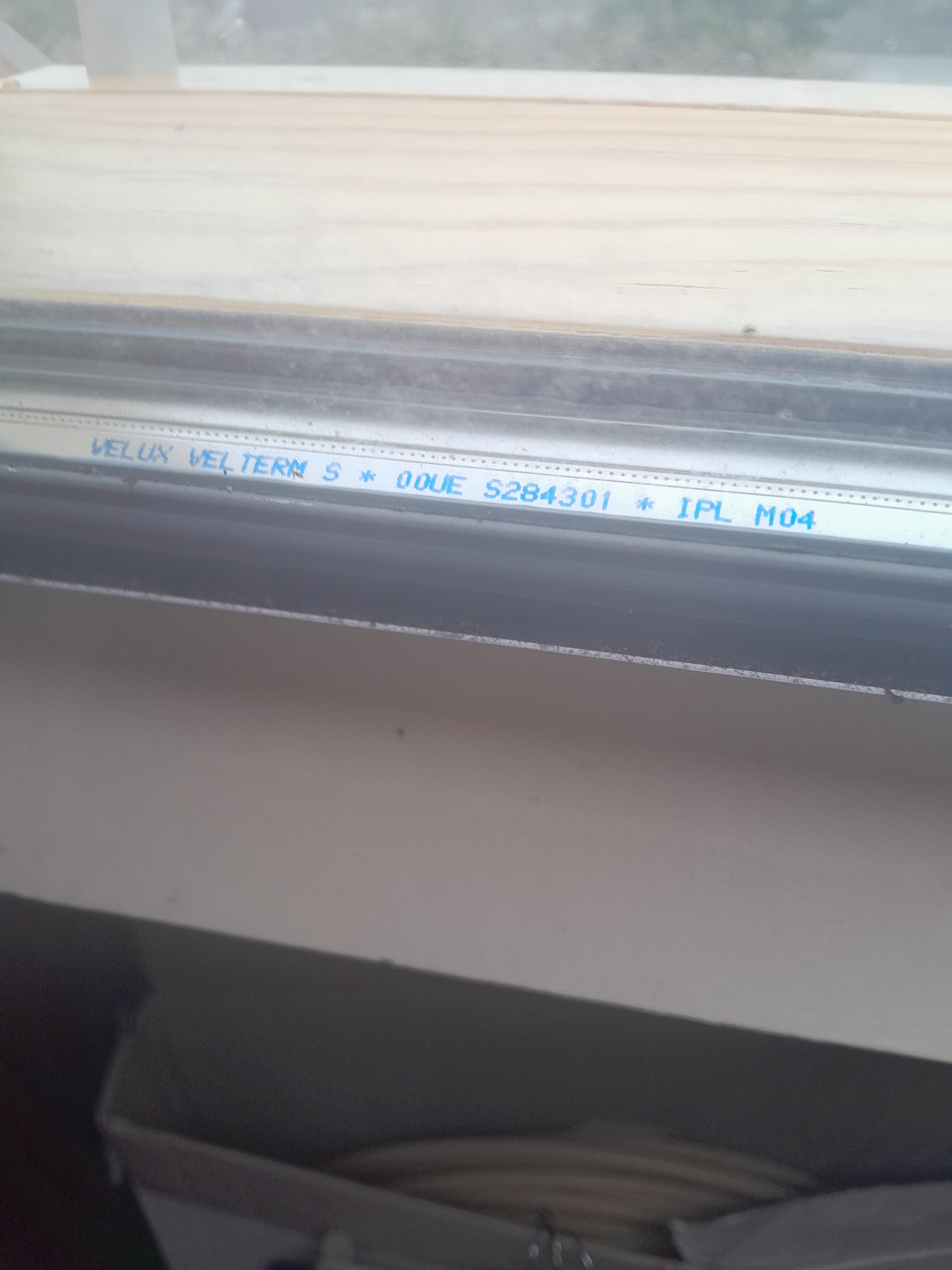
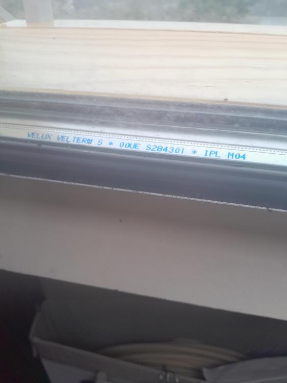
I don't know if this is generally known but I wasn't aware of it until a Velux repairer (kindly) told me that some of these windows manufactured around 2001, see code below are replaced FOC, its a batch with code OOUE. I don't know if you contact them even if you have no cracks if they still replace them. I returned from holidays to find a large crack in one of two attic windows, both window modules were replaced, what a service after 23 years. Apparently a vacuum forms between the two glasses and the inner one then can crack/shatter, the installer told me the glass thickness is now 8mm vs 4mm.
-
boiler behaviour,please let me know your thoughts.
John Carroll replied to Post and beam's topic in Boilers & Hot Water Tanks
Yes, measure that temperature from the tap, the important one from a trouble shooting point of view is the boiler flow temperature which you should be able to access fairly easily from the menu, in DHW mode this temperature changes with the DHW demand, the DHW flow rate and temperature, and the mains temperature, unless the PHEX (plate heat exchanger) is very fouled then this should't remotely approach the blocking temperature, in any case if this was happening you would have noticed the shower/tap running hot and cold. -
boiler behaviour,please let me know your thoughts.
John Carroll replied to Post and beam's topic in Boilers & Hot Water Tanks
OK, if this happen after using DHW constantly with no demand for CH in between (DHW demands) and if the boiler flow temperature is anywhere in the region I posted above during DHW demand then blocking code 2965 simply cannot be true which I would point out again to WB. If its coming up during a CH demand or CH anticycle or overrun then it will have to rise to whatever temperature it operates at, probably greater than 90C, unlikely, but possible, IMO. Again just observe the flow temperature for the pump overrun time after switching off the CH demand and see what temperature it rises to. -
boiler behaviour,please let me know your thoughts.
John Carroll replied to Post and beam's topic in Boilers & Hot Water Tanks
Has it ever cleared itself without you resetting it?, if not then it doesn't point to this 2965 fault which is self clearing. I took some readings from someone with a WC 36CDI that had a fouled PHEX, it wasn't locking up but you might get some idea of the expected boiler flow temperature when it is producing HW. Fouled PHEX, (DHW setpoint 55C). DHW flowrate: 9.2LPM. DHW Temperature: 44.5C. Boiler flowtemp: 71.5C. Boiler output 16.4kw Mains Temp:19.0C NEW PHEX, (DHW setpoint 55C). DHW flowrate: 10.0LPM. DHW Temperature: 54.5C. Boiler flowtemp: 64.5C. Boiler output 24.1kw. Mains Temp:19.6C. -
boiler behaviour,please let me know your thoughts.
John Carroll replied to Post and beam's topic in Boilers & Hot Water Tanks
Even if the blocking code is up and assuming the boiler will/does c/o to HW then the pump can now flow enough through the PHEX, the blocking code should disappear very rapidly due to cold water on the other side of the PHEX, boiler fires up. -
boiler behaviour,please let me know your thoughts.
John Carroll replied to Post and beam's topic in Boilers & Hot Water Tanks
Exactly, the boiler flowtemp can be set to 82C and if/when it does exceed this or any target temperature then the burner will cut out once/if the temp goes 5C higher, pump continues running to reduce the temperature to enable the boiler to refire again after a suitable (anticycle) period, all standard practice. When you c/o to DHW then cold DHW has to flow through the plate heat exchanger before the boiler refires and as long as the DHW flowrate is greater than 3.3LPM then the DHW will not reach the overtemp setting of I think ~ 85C/90C on say 65% fire up ignition conditions. If, as I asked previously, there are no problems with repeated DHW operations? then looks very much like a poor design feature if it prevents the boiler from firing until the (CH) recycle time or whatever has elapsed. Also fault code 2965 should not be flagged under the above conditions -
boiler behaviour,please let me know your thoughts.
John Carroll replied to Post and beam's topic in Boilers & Hot Water Tanks
There must be thousands of combi boilers which have to deal with a similar cycling problem on CH, a combi boiler is sized for its HW duty, you may have a 37kw boiler sized to give a DHW flow of 15LPM at a dT of 35C but the CH load might fall to 5kw so the boiler just has to cycle, a 37kw boiler may have a minimum output of 6kw so not a big deal, older ones like the Vaillant ecotec plus 837 can only modulate to 12kw but still have to deal with very low CH demands. The main challenge, especially with Vaillants, which (used to at any rate) maintain the ignition conditions for 60 seconds after recycle/refire, is that they fire at ~ 65% of their max output and if they don't modulate down fast enough then the burner will trip at the target temp +5C leading to anticycle and refiring, nearly all boilers can be range rated right down to their minimum output which doesnt affect the DHW output but they will still refire at this very high output, the range rating does help but not directly. Overshooting the target temperature is a quite normal event and all boilers will then not refire until the anticycle time has elapsed and providing the flowtemp is target temp -5C or lower. I wouldn't have thought that changing to HW demand even if the boiler is in anticycle at the time should delay the (DHW demand) refiring as long as the flow temperature is less than the HI limit trip which is probably as high as 90C. The (primary) flow temperature then changes based on the HW demand and the set DHW temperature. -
boiler behaviour,please let me know your thoughts.
John Carroll replied to Post and beam's topic in Boilers & Hot Water Tanks
As a matter of interest, was this problem occuring during the summer when there was no demand for CH or is it only happening (occasionally) when switching from CH to HW? -
boiler behaviour,please let me know your thoughts.
John Carroll replied to Post and beam's topic in Boilers & Hot Water Tanks
If the mains flowrate through the boiler isn't greater than ~ 2.5LPM then the flow switch won't activate to fire the boiler, this can happen if the crossover in any mixer is preventing this. The mains or boiler low temperature has nothing to do with firing up the boiler in DHW mode, its only the mains flowrate that calls for burner operation. -
boiler behaviour,please let me know your thoughts.
John Carroll replied to Post and beam's topic in Boilers & Hot Water Tanks
You may have a xover problem with a mixer. Can you turn off the cold water supply to your shower and mixing taps, reduce the DHW temp setpoint to 40C and see if combi fires up when you switch on the shower. -
As above or with flow switch made check for 220/240V between the (switched) L&N terminals where the pump is connected in, if 2220/240V, get any sort of load like a 60/100W bulb and see that it lights when you wire in to the same terminals.
-
If you can't find the HEX dP/flowrate in the boiler MIs, I would ring Baxi and request it, you may well find that its only 3.0M or so at your required flowrate, also ask what is the pump head, most now are 7.0M which should still give ~ 6.0M at 23LPM, a HEX dP of 3.0M then still leaves 3.0M to circulate through the systems which may be sufficiend.