John Carroll
-
Posts
577 -
Joined
-
Last visited
-
Days Won
3
Everything posted by John Carroll
-
I'm well (well) over 70 but I just divide BTU by 3412 to get KW.
-
Your total heating demand is 16kw with a required flowrate of 23 LPM. All boiler makers base their max flowrate based on a dT of 20C, not because they care about condensing but because the boiler HEX head loss is based on this, a typical max HEX loss might be 3.5M at max flow. If the installed boiler is rated at 20kw then its max flowrate is, 20*860/60/20, 14.3LPM, if the HEX dP is 3.5M at this flowrate, then its 3.5*(23/14.3)^2, 9.1M at a flowrate of 23LPM, a non runner maybe even with a LLH, this assumes you require both CH&UFH on together. (if my calcs are correct).
-
Unvented HW Cylinders with internal expansion
John Carroll replied to John Carroll's topic in Boilers & Hot Water Tanks
I'd be a little surprised if this happens. What drew by attention to this bubble was that years ago I recharged it for someone who used up all the hot water immediately before I recharged it and to my surprise, when I shut the cold feed and opened the T&PRV, very hot water kept draining out until the T&PRV started gurgling. -
Unvented HW Cylinders with internal expansion
John Carroll replied to John Carroll's topic in Boilers & Hot Water Tanks
Almost the entire volume (92%) is/can be reheated but the volume above the bottom of the dip tube cannot be used?. -
Questions/Issues with new UVC System
John Carroll replied to Spinny's topic in Boilers & Hot Water Tanks
-
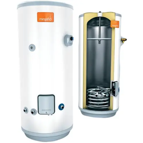
UVCs like Megaflo and Gledhill Premium have a air bubble in the top to allow for expansion, these have a dip tube which extends down to just below the level of the T&PRV which is dimensionally ~ 34% down from the top of the cylinder with the dip tube say 36% from the top, which in a nominally sized 150L cylinder only leaves 96L of usable HW?. When the cylinder is pressurized to its normal 3.0bar via the pressure reducing valve there will then be 136.5L of cold water in the cylinder, if this cold water say at 15C is then heated to 60C, the expanded volume of 2.21L will give a total (hot) volume of 138.7L (cylinder pressure 3.8 bar) but only 96L of this is available as once this vol is used, cold water will then enter the bottom of the dip tube and there will be 43L of HW above this which cannot be utilized. Gledhill figures suggest that the capacity of these cylinders is 90% of the nominal capacity which it ~ is but its certainly not available as HW IMO. Has anyone noticed that these cylinders run out of HW sooner than might be expected I wonder?
-
Very interseting Video, that's certainly a lot of safety gear for a relatively cheap purchase price.

-
A huge proportion of UK gas boilers are combi so one would think that all these would be, in the main, very oversized, a fairly modest 32kw might only have a 15kw heating load, most can be range rated but if cycling, for whatever reason, will still fire up at ~ 65% of their rated output which will, more than likely cause problems if WC and only looking for say 35C/40C flow temperature.
-
What make/model and minimum output is your boiler?.
-
This is very interesting but I suppose there should really be a new thread. Even if the circ pump is not controlled/modulated then the dT will decrease with reduced flow temperature. If you use a fixed flow rate of 1.0LPM/kw then WC will result in the following example temperatures, flow/return/dT...... 65.0C/54.4C/10.6C. 45.0C/39.9C/5.1C. 40.0C/36.2C/3.8C. (Assumes a required room temp of 20C)
-
I know Vaillants have a internal bypass that defaults to 2.5M and is adjustable to I think a max of 3.5M, some also have a HEX dP of 4.0M at max flow rate, this is why 20C is used as the dT, a 20kw boiler will have a max flowrate of, (20*860/60/20), 14.3LPM, a 32kw boiler, 23LPM etc, most boilers now have a 7M pump and will still have a head of ~ 6.5M at the rated boiler flowrate, this then leaves around 2.5/3.0M to circulate the water through the system, more than that or even less, in some systems, a LLH or CCTs will then have to be installed, the primary side will deal with the boiler HEX dP and another circ pump on the secondary side looks after the system losses. The dP through a HEX designed for a 4M dP at say 20LPM will only have a dP of 0.56M at 15LPM and only 0.25M at 10LPM, so the bypass will be open for a lot of the time, 12LPM will result in a ~ 10kw rad output but because the HEX dP is only 0.25M then there is around 5.5M/6M remaining which will cause quite a lot of recirc with very high return temps at the boiler so you can be measuring a dT of 10C at the boiler flow/return but the actual dT might only be a few degrees so maybe this why the boiler trips, its easy to check that out where you can read off the return (as well as the flow) temperature in the boiler menu and compare them with the measured temperatures. The newer vaillants now have a settable dT of between 10C & 20C which modulates the pump to a minimum speed of 50%. I know someone with this boiler but cannot achieve this, he is now trying the pump on manual set to 50% so awaiting results.
-
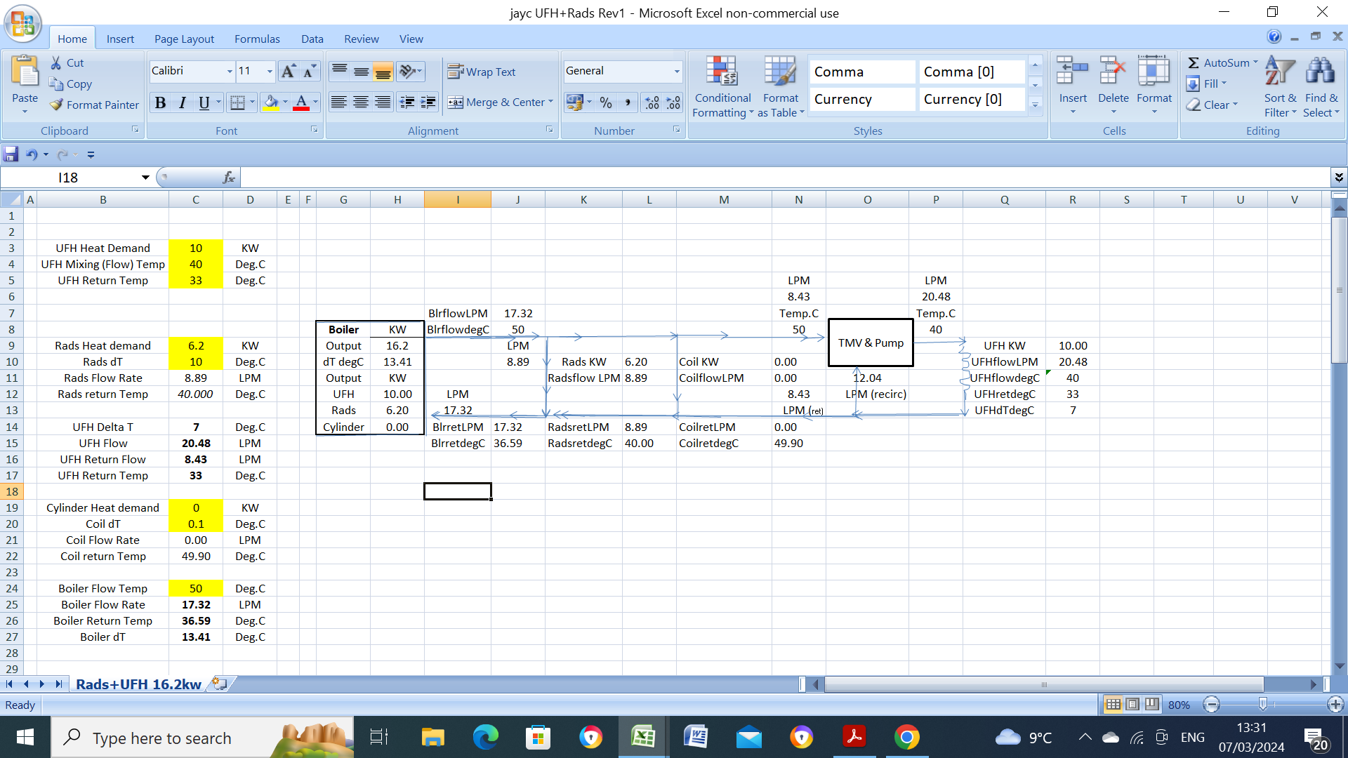
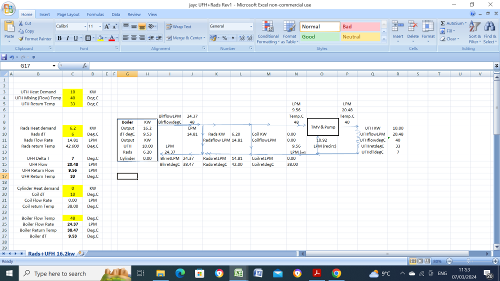
The boiler dT of 9.5C is because (UFH return) 9.56LPM at 33C is mixing with (Rad return) 14.81LPM at 42C to give a mixed return of 24.37LPM at 38.5C, boiler dT, 48C-38.5C, 9.5C. When WC keeps reducing the boiler flow temp then the rad output obviously reduces but the boiler shouldn't cycle unless its minimum output is greater than the heating demand or if, for some reason the boiler dT exceeds 30C. Also when/if the boiler does refire then it will refire at around 65% of maximum output and the flow temp will oftern exceed the target temp by 5C means burner trip and recycle especially if the WC has driven it down to say 40/45C. "But also one question - how do you achieve the 24lpm boiler flow rate if the boiler pump flow rate is max 20lpm? Surely then you need hydraulic separation to run higher boiler flow/return temps and then higher flow rates for the low temp rads/ufh?", A 32kw boiler with a dT of 20C, will have flowrate of (32*860/60/20), 23LPM so a flow rate of 24LPM will only result in a dP of 3.8M, a increase of 0.3M (assuming a design HEX dP of 3.5M) but if the boiler flow temp is increase by only 2C to 50C then the flowrate decreases to only 17.32LPM because the UFH return flow has fallen from 9.56LPM to 8.43LPM and the rads (because they can now be throttled in to give the same output at a flow of 50C vs 48C, rad dT is now 10C vs 6C) from 14.8LPM to 8.9LPM. So the higher the boiler flow temperature the lower the flowrate, the UFH will automatically reduce the return flowrate by recirc more through the mixer, the rads have to be manually throttled or have TRVs.

-
This may (or may not) be of some help of seeing the "total" picture, I configured this when my daughter was installing UFH and just tailored it to your UFH + rad heating demands, I'm not sure when you say spec'd for DT25 if you mean rads designed as "T25" rads?, if so they will give a rad output of 40.6% of T50 sized rads and would require a oversizing factor of X2.46. say 2.5. I'm also assuming that the required boiler flow temperature required is 48C and the UFH required manifold temp is 40C. I didn't include cylinder heating.
-
What ever about torqueing, the screws were certainly well tightened as were all the other CU cables. A 40A RCBO should be well able IMO to carry 40A, a type B can carry 1.2/1.25 times rated current (~ 50A) for hours on end, > 10, 000 secs according to the charts. My own "230V" supply was giving 240V at the (running) 9.0kw shower terminals for about 10 years before returning to normal so I had a lovely 9.8kw shower drawing nearly 41A, the same B40 RCBO is the original, installed in 2007.
-
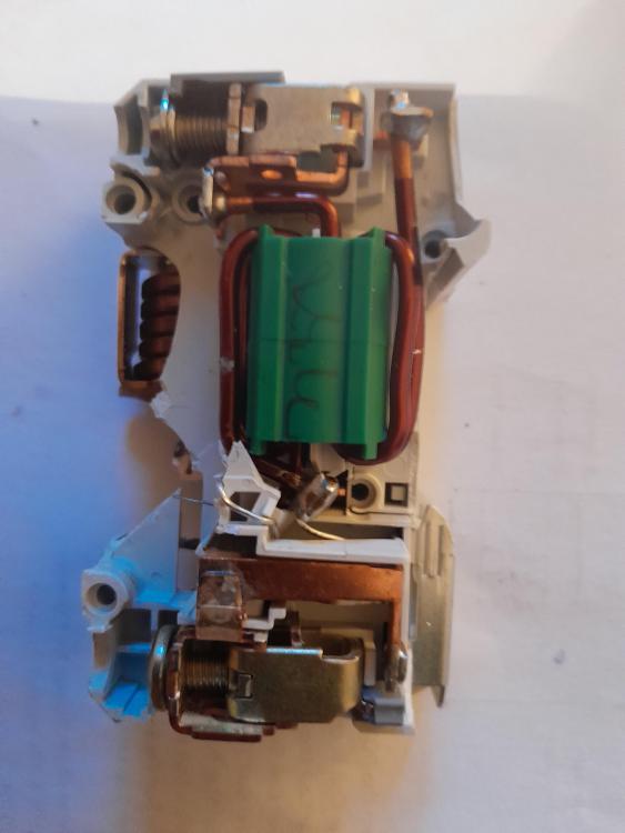
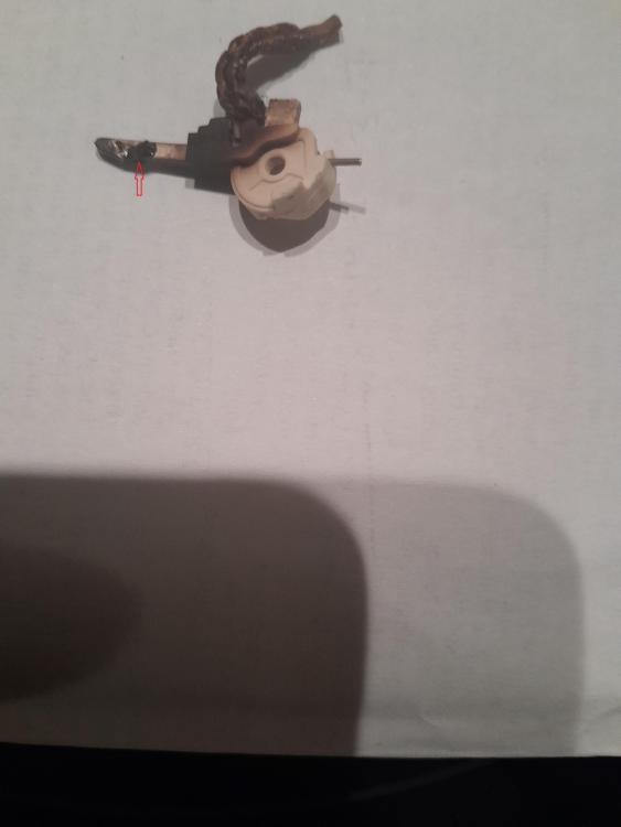
Stayed in daughters house at weekend, had a shower on Saturday, checked trip switch on the RCBO a few hours later, RCBO tripped & reset . Got a call on Sunday morning, no power on shower, found no continuity between the RCBO live contacts, renewed RCBO. Checked shower power at 8.8kw (9.0kw shower) using the smart meter flashing LED. Broke open the failed RCBO (Hager 40A/30ma) and found signs of overheating, the contact (shown below) closes downward, there is a layer of what looks like melted plastic as shown by the arrow which was attached underneat the contact as well which probably prevented the contact closing or it closed with this plastic insulation preventing continuity, I get OC on the M.Meter when testing from the blob of plastic to the contact, also signs of overheating inside the RCBO. I wonder what would have happened if I hadn't tested the RCBO?, I do test it ~ once/annum, this was the original RCBO, installed when the house was built in 2006. The shower is switched on/off at the shower, then isolated each time with the pull cord, this RCBO has never opened/closed on load, is this a unusual failure?
-
HW cylinders will generally have a EV sized to not less than 10% of the cylinder volume, and are installed with a PRV (pressure reducing valve) set to 3.0 bar, the EV should then be precharged to 3.0 bar, (2.8 bar is recommended, as it apparently helps to prevent water hammer). If the OPs EV is sized to this 10% minimum then the air end pressure would have had to fall to ~ 0.3bar to cause the T&PRV to lift at 7.0 bar when the cylinder temperature reached 60C. Spraying the air end schrader valve and where it exits the EV with soapy water will often show this, the cylinder then has to be de pressurized and the air end pressure checked, if its down to 0.5bar or less and no leakage has been detected then maybe get it recharged to 2.8/3.0 bar especially if it hasn't been checked at the last service.
-
Can you post the volume of both the HW cylinder and the expansion vessel and the pressure of the cold water to the cylinder or the PRV setting, normally 3.0 bar.
-
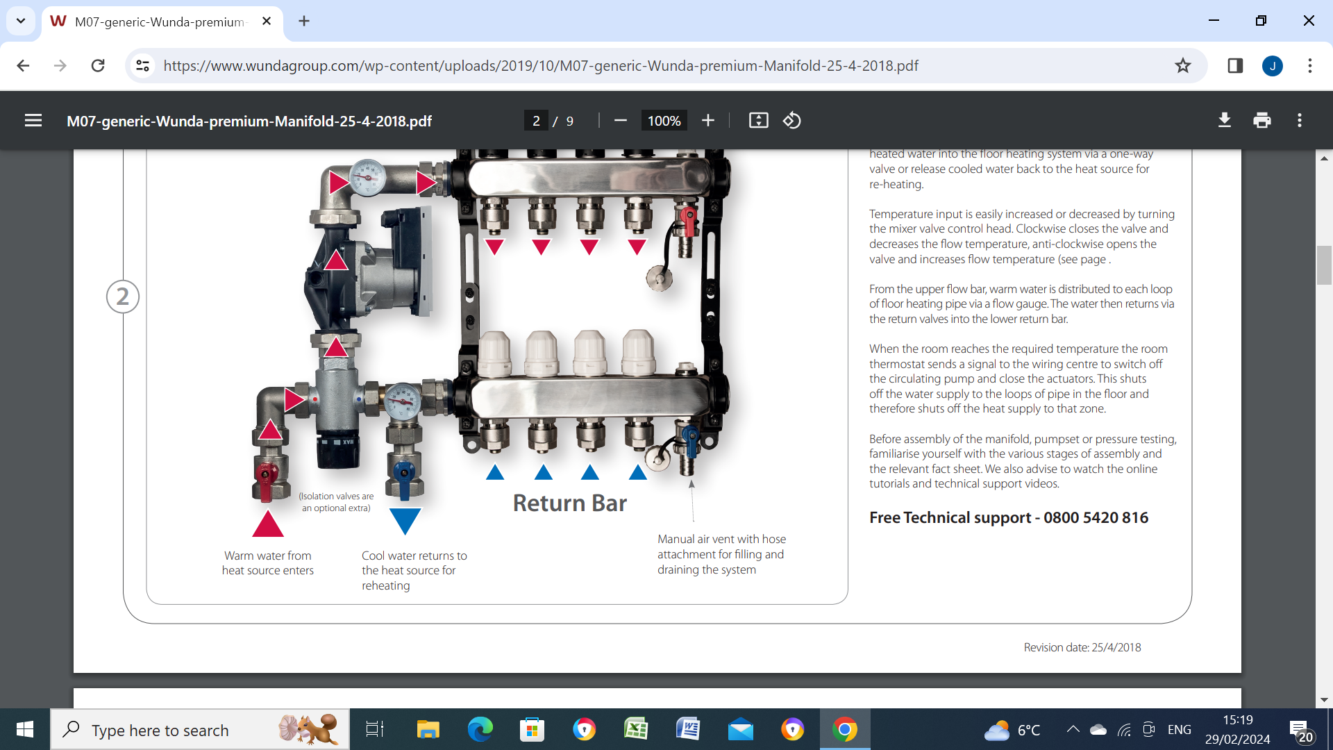
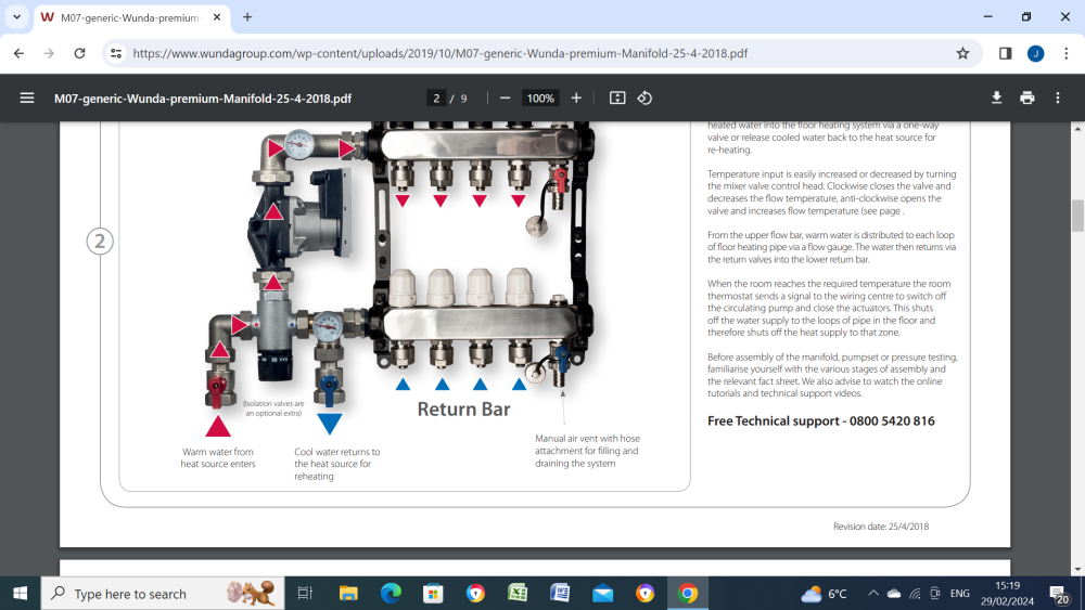
Maybe no harm in getting two thermometers like shown as they give useful info on the UFH flow and return temperatures, ask them can these can be installed on your basic version.
-
That's important but one might expect ~ a 10C/12C dT so returns around 48C/46C. Each loop will then, at a 2LPM flowrate will emit 2*60*11/860, 1.53kw, gives some idea of what you might expect depending on number of loops.
-
Anyone had first hand experience of Shower Power Boosters?
John Carroll replied to Del-inquent's topic in General Plumbing
I have never seen real pump curves for these shower boosters but I did a few sums a few years ago for somone who had a gravity fed shower (U/stairs bathroom) with mains cold feed reduced via a PRV and gravity hot, the gravity hot gave a head of ~ 2.5M and the shower flowrate was 3.5LPM. The calc I made up years ago and occasionally use is. watts = M*LPM/(6.14*n), where n = pump&motor efficiency, don't know what the overall efficiency of these pumps are but I assumed 40% overall, I came up with a equilibrium flowrate of 5.9LPM at a head of 7.5M (0.75bar), a boost of 5M (0.5bar. My calcs were LPM = 12*6.14*0.4/5, 5.9LPM, the shower head with a boost from 2.5M to 7.5M should give a increased flow of sqroot (7.5/2.5), 1.73, 1.73*3.5, 6.1LPM so reasonably close to the pump calculation for equilibrium, don't know if he installed this booster or not as I heard no more. It would be interesting if someone who has one or two of these boosters installed in a gravity shower to inform of the increased flow rate. -
Heat loss over time (Vented Cylinder)
John Carroll replied to marshian's topic in Boilers & Hot Water Tanks
IF the gravity circulation is reverse flow through the cylinder coil then you could just install a NRV on the coil inlet. -
Heat loss over time (Vented Cylinder)
John Carroll replied to marshian's topic in Boilers & Hot Water Tanks
Assuming the MPV is normally wired then I can't see how the it will change to the HW position unless the cylinder stat is also calling for heat as well as programming it on as the cylinder stat satisfied contact will still be providing 230V to the grey wire and will keep the valve powered in the CH position?. -
Heat loss over time (Vented Cylinder)
John Carroll replied to marshian's topic in Boilers & Hot Water Tanks
That's interesting, some would like if the MPV allways returned to a unpowered default position of HW, especially overnight, some may think that this can be accomplishied by programming the HW (last) on for a few minutes but this will only work if the cylinder stat is also calling, otherwise the valve will stay powered up in CH as "its last port of call". I attach a modified schematic for anyone who's interested in making the MPV allways return to the unpowered HW position.
-
The above is installed in a 300L HeatraeSadia Santon Premier Plus unvented cylinder switching a motorised 2 port valve on the cylinder coil, apparently its differential switching is only 1.5C, switches off at 60C but on again at 58.5C, I can't find any info in the spec sheets re the differential switching but would have thought it should be somewhere in the 5C to 10C range like most cylinder stats. Any info on this stat from anyone?
-
Fluorescent Tube Starting
John Carroll replied to John Carroll's topic in Electrics - Kitchen & Bathroom
Just finished installing a (almost) 4 ft, 36W Evolec LED Slimline with a alleged rated life of 25,000 hrs, ~ £25, no problem in hanging it as I just used the original two securing screws with the supplied brackets, you then just clip on the lightweight fixture in any almost position you require.