John Carroll
-
Posts
577 -
Joined
-
Last visited
-
Days Won
3
Everything posted by John Carroll
-
There seems to be a balanced cold teed off (incorrectly IMO) after the valve combination set, this should be taken from the PRV balanced cold port and before the check valve. If you open a (balanced) cold tap before drawing off any HW, do you get this noise?, if you dont, shut the isolating blue lever valve on the balanced cold before opening the HW after the next re heat and check for noise.
-
The problem with top mounted elements IMO is that they heat the water uniformly in a stratified state so if say the top 20L or so of water is at 40C and the remainder is at 20C then the 20C remaining water will only have reached 40C and that top 20L will have reached 60C, the normal stat which measures the average temperature of the water its immersed in will not switch off until the average temperature is 60C so that top 20L may become very hot, the cylinder will heat perfectly uniformly if all the cylinder volume is at the same temperature, your proposed stat location could result in a even higher temperature gradient as its only measuring the water in the cylinder bottom. If the cylinder has no heating coil then you should be able to install a 36" immersion which should give you a extra 20L or so of hot water.
-
Change the sterilisation day and see does the consumption follow it.
-
Fixed Speed or Modulating (CH/HW Circulation pump)
John Carroll replied to marshian's topic in Boilers & Hot Water Tanks
The "push button" UPS2 50/60 130 flows ~ 10/15% more than the Evosta3 60 (6M) but the old Grundfos selectric is a good bit less, you do have the Evosta3 60 (6M) and not the Evosta3 40 (4m) model ??. -
Fixed Speed or Modulating (CH/HW Circulation pump)
John Carroll replied to marshian's topic in Boilers & Hot Water Tanks
You have wisely choosen a pump that displays the flowrate in m3/hr which you may find very useful when you commission the CH, I have tuned a few relations systems with/without WC and I set the flowrate to 1.0LPM per KW of rated rad(s) output, your system, assuming total rated rad output of 15kw would require a flowrate of 15.0LPM (0.94m3/hr), would suggest setting the pump on CC2 (constant curve) "speed 2" or CP2 (constant pressure) both 3M pump head, and see how it goes, the setting can, if required be increased to CP3 (4.5M pump head.) I would also suggest that you install a digital roomstat somewhere, ( I have mine in the combined two rooms where we spend most of our time), Viessmann seem to think that WC alone is only required? but again IMO, the OT can fall or rise by 6 or 8C over a 1 or two hour period which can result in over/undershoot of the room temps, at least you have a master control with one roomstat. -
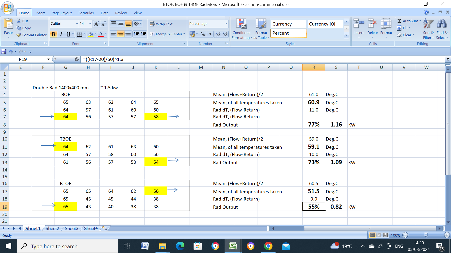
Here are my actual readings. The BTOE is by far the worst, even though the (flow+return)/2 was 60.5C, the actual mean temp was only 51.5C.

-
Termostatic shower trouble since Heatpump installed
John Carroll replied to Sols's topic in Air Source Heat Pumps (ASHP)
Not ideal of course, or if the remaining users can put up with 1.0bar H&C maybe just reduce the UV cylinder PRV to 1.0/1.5bar, wonder what pressure its actually running at with 15/20 LPM draw off even if set to 3.0bar. -
Termostatic shower trouble since Heatpump installed
John Carroll replied to Sols's topic in Air Source Heat Pumps (ASHP)
I have seen pumped electric showers fed fom the mains with a reducing valve, it invalidates any warranty but probably not an issue for you, you could install reducing valves on the hot and cold supplies to the shower set to 1.0bar which I think is the maximum allowable inlet head. -
Termostatic shower trouble since Heatpump installed
John Carroll replied to Sols's topic in Air Source Heat Pumps (ASHP)
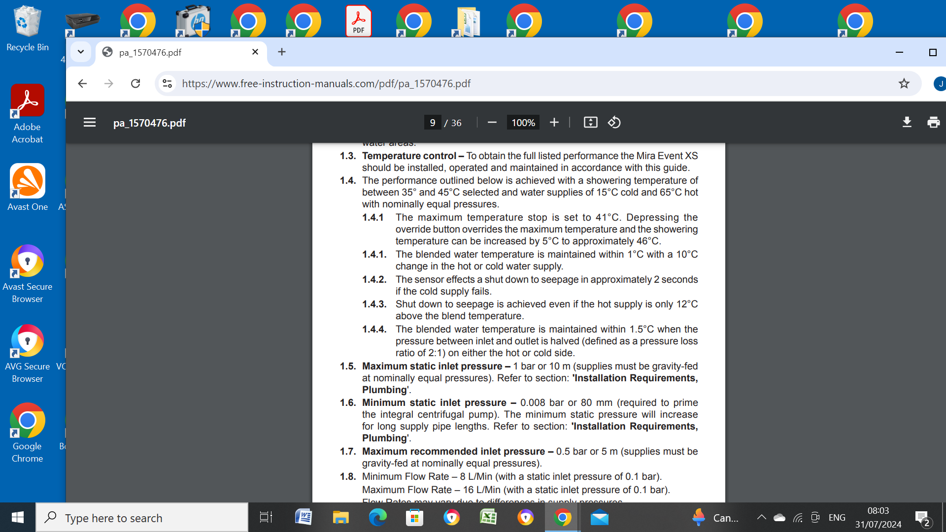
You now have the HW at 48C, what cylinder temp were you maintaining with the gas boiler?, the TMV is doing well to maintain a showering temp of say 40C even though it shouldn't be noisy, do Mira specify a minimum differential temperature for the Event XS?. Some general info, below.
-
My system has a de aerator (manual venting) installed at the pump station, I recharged my (flat plate) system last year because of a leak on this de aerator body, did get some air afterwards when venting but not a huge amount.
-
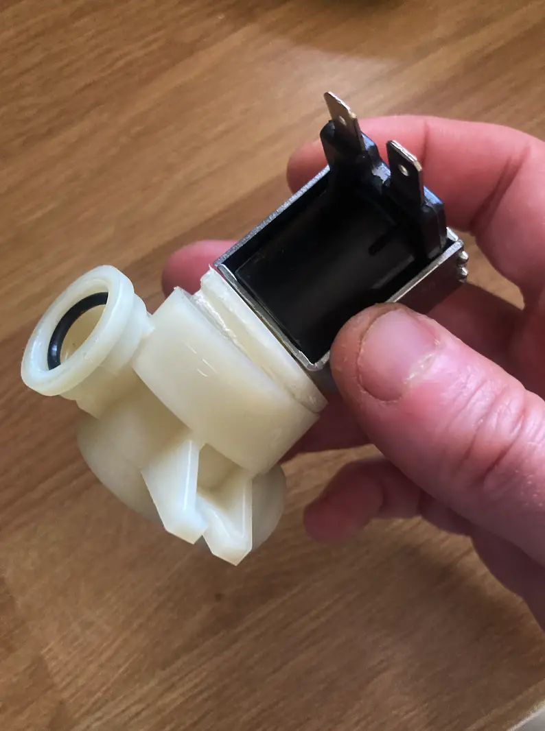
Not mine but definitely seems to be some form of flow regulator based on the incoming water temperature but why it is installed on the supply to a electric shower is very strange so will suggest just removing it.
-
As above, installed between the mains and a newish electric shower, shower flow stops when weather gets warm or during the day as it heats up, its a dedicated supply to the shower.
-
Is your accumulator pumped, if so, what is it pressurizes to?, obviously the higher the accumulated pressure and the lower the minimum required dynamic pressure the greater the useful accumulator volume. A 300L accumulator with a precharge pressure of 2.0bar and a final pressure of 3.5bar will supply 100L, in falling from 3.5bar to 2.0bar but if pressurized to 6.0bar will supply 171L, in falling from 6.0bar to 2.0bar, and/or 150L if pressurized to 5.0bar.
-
Triton T80 Easi fit electric shower solenoid
John Carroll replied to John Carroll's topic in Bathrooms, Ensuites & Wetrooms
Its just taken directly off the mains supply I believe but is only used very occasionally but wouldn't think that the pressure should be excessive. -
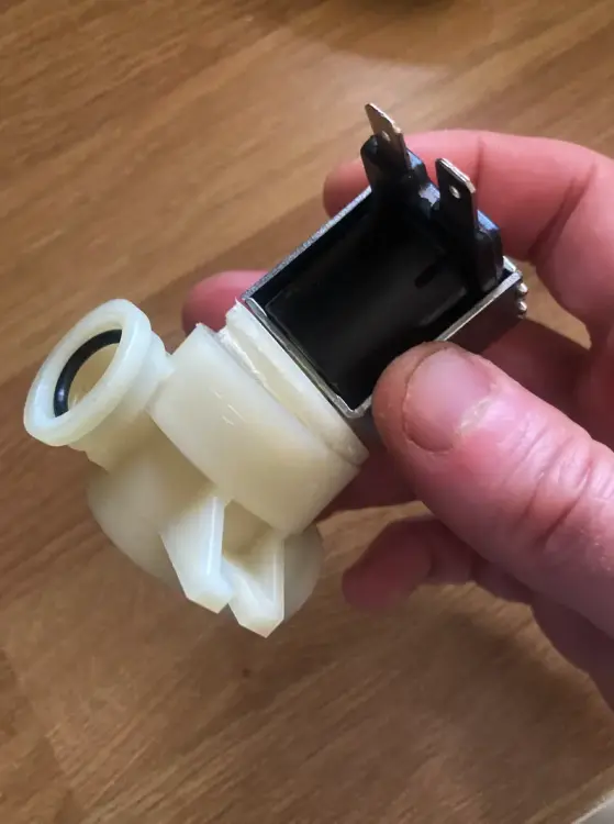
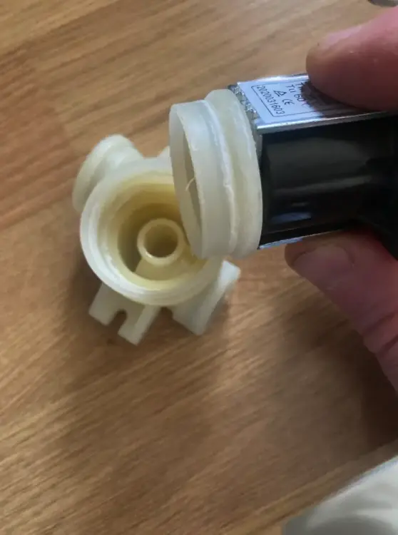
Has anyone had a leakage problem with this type of solenoid assembly? these are probably used in other shower makes, the top body part is glued into the bottom part, below is one from someone on another site where the two pieces actually parted company with the shower off, these showers are designed for a static mains pressure of up to 10.0bar.
-
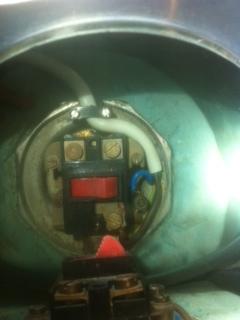
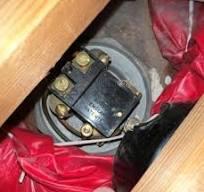
I have a 52 year old Santon dual element immersion which has the sink/bath change over switch together with a Otter dualstat thermostat mounted on top of the immersion, (3 wire) I installed this in 1972 (new house, then) and I self installed a modest solar thermal system 11 years ago and installed a new twin coil cylinder, I removed the immersion from the old cylinder and reinstalled it in this cylinder. Its still working perfectly but I only occasionally use the sink (short) element). It doesn't have the rod type thermostat so it would seem that these Otter type stats are just surface mounted to the immersion top. Below is a photo of mine and I also include a photo of a immersion from someone who had a Otter Dualstat K71 stat, can't remember if mine is K71 but I imagine the operating principles are the same. Someone may have renewed one of these in the distant past and know how they work?
-
I wonder where the solar store temperature (control) probe was inserted when the cylinder stat probe was in 6?, it should allways have been be in position 6, just above the solar coil inlet, if its in 12 then this might actually result in recooling of the water just above the coil inlet and result in less than optimum performance of the solar system.
-
Not a problem, as you say, with a pumped Willis, but certainly (IMO) will tend to cause problems with the normal installation as the outlet temperature will run much higher due to the very slow circulation rate and release more air?, I have read of the heating elements failing due to air build up if installed with the immersion on the top,
-
I have no theoretical basis, I just see that the UFH output isn't a straight line which may have indicated a not quite linear relationship.
-
Fig 2 is interesting. At pipe centres of 200mm, the floor heat output at 45C is 75W/m2 (floor area), 40C is 58W/m2 & 35C is 43W, if one was to use a 20C required room temperature and use a exponential of 1.15 then it matches the outputs reasonably well, for example the output at 40C = ((40-20)/45-20))^1.15 X 75, 58W/m2 and at 35C = ((35-20)/(45-20))^1.15 X 75, 41.7W/m2.
-
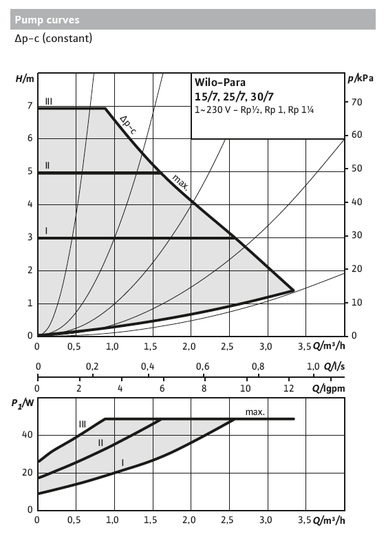
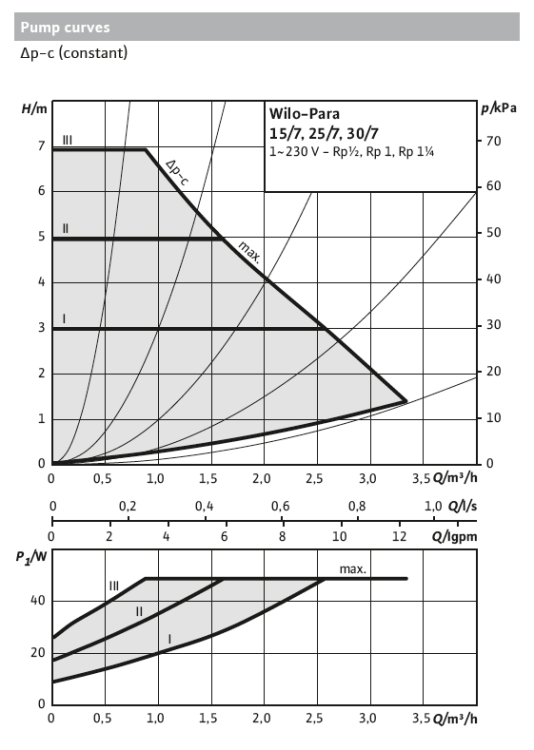
Whatever about the thermal mix. would suggest CPi setting at 3M initially, 3M (2.8) should be sufficient to circulate 3.0LPM through each 100M loop, total 12.0LPM, 0.72m3/hr, as long as there is a bit of adjustment left in the (max) flow loop regulator then its fine, if not, go to CPii, 5M setting. In practice, the flow requirement will probably be less than 3.0LPM/loop. "4 loops, 2 zones, 400m, 16mm Pex-al-Pex, biscuit mix between joist, Wilo Para pump as in the picture. Pipes tested at 5bar."
-
What kind of manifold flow temperature?.
-
The top icon (your pump, below) shows the pump in Constant Curve, CC, mode or better known in older pumps as constant speed, it has 3 settings, yours may be a 2M, 4.5M & 7M setting, corresponding to i,ii&iii, the higher the setting the greater the pump head and the greater the flow rate, its primarily used for radiators and sometimes UFH but the the second icon setting, Constant pressure or CP mode is generally recommended, the settings may be somewhat similar to the CC settings, the difference is that the pressure is held constant at whatever setting you set it to, the third icon shows Proportional Pressure or PP control where the pump head decreases with decreasing flow demand like rads fitted with TRVs, a example is my own, I have 8 rads on TRV control, I have the pump (Wilo Yonos Pico) set to PP 4.6M which gives me my required flowrate of 13LPM at a pump head of 3.5M, as the TRVs throttle down the pump (speed) and head reduce to ~ 2.8M resulting in reduced power consumption and no noise from the TRVs when well throttled down, power consumption varies from ~ 23 watts down to 14/16 watts.
-
The Willis should be installed with the heating element underneath otherwise air can build up causing problems.
-
Suggest the centre one, II, (constant pressure) there are three setting, i,ii & iii,, try ii for a start.