Jeremy Harris
-
Posts
26430 -
Joined
-
Last visited
-
Days Won
360
Everything posted by Jeremy Harris
-

Sourcing our plumbing equipment for first fix
Jeremy Harris replied to JanetE's topic in General Plumbing
FWIW, all the MSP (modified silicone polymer) sealants are a million times better than RTV (especially acetoxy cure) silicone, in fact close to being as good as moisture-curing PU sealants in terms of adhesion and long term stability, but less harmful (no isocyanates) and easier to use. There are other brands, too, and to some extent it depends where you live as to who stocks what. I used the Sikaflex 95 MSP adhesive to bond our flooring down, and that seems to be near-identical to CT1 (apart from the colour) in terms of bonding and sealing performance. I've not found anything yet that matches CT1 exactly, but some of the other MSP/silane sealants are very close in both performance and appearance. -
It may well work OK, as our house similarly blocks mobile phone signals completely, but these short range radios seem to have no real problem going though the wall or windows. The advantage they have is that the lower frequency is better at getting through buildings, they use a very low data rate that extends the range for a given power to maybe three or four times that of a mobile phone and they have a better antenna and almost certainly a more sensitive receiver (mobile phone receivers have to deal with poor built-in antennas and lots of digital noise from the phone circuitry). If it is a problem for your location, then adding an external antenna to the outdoor box will just about double the performance, and is probably the easiest thing to do.
-
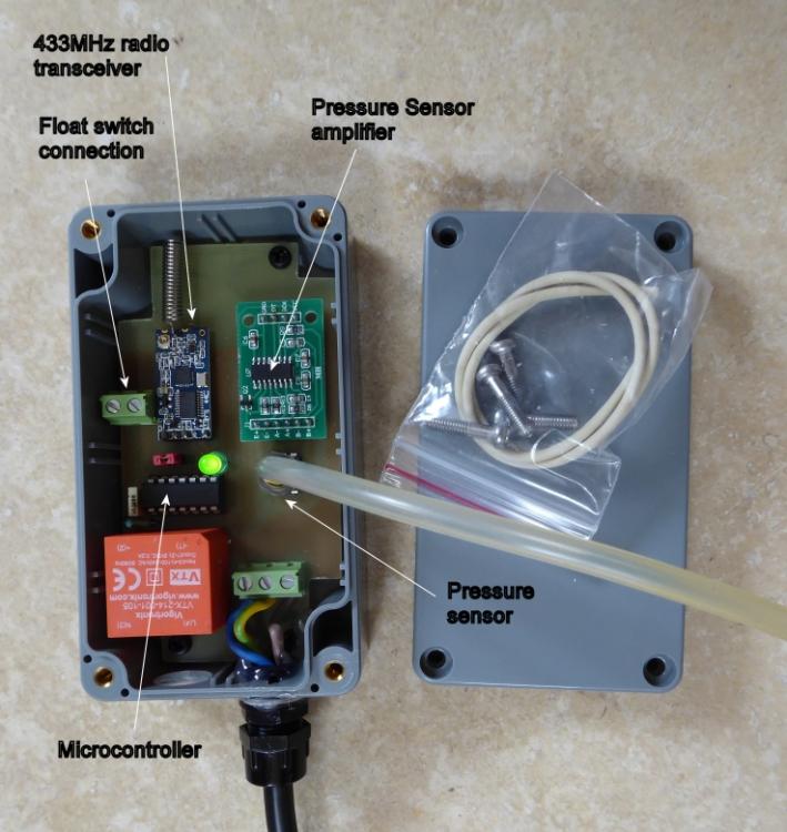
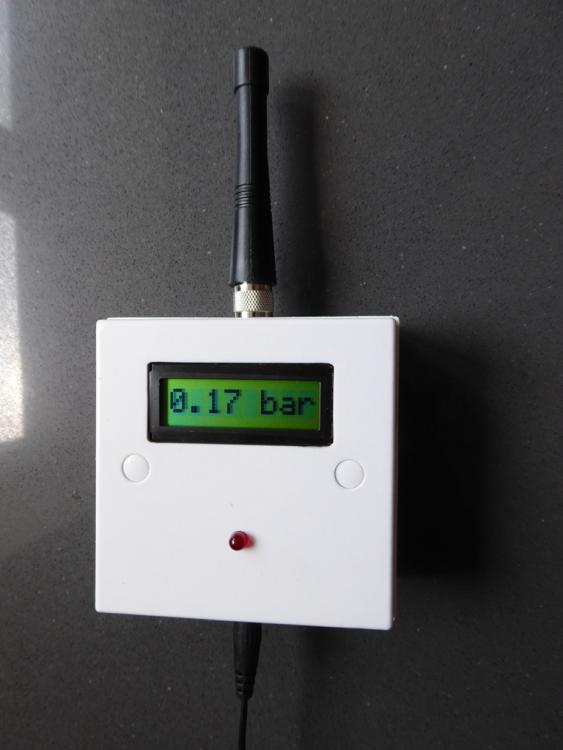
Right, I made a start at the weekend (as light relief from collating VAT receipts) and made up a prototype. It's very much a prototype, and although I may end with it installed on our system, there are probably things I will change for "production" versions, just to make them a bit easier to make, and a bit neater. First off, this is the small waterproof box that goes at the treatment plant end: I should have added a scale, but the air pipe to the pressure sensor is about 5mm in diameter and the case is 65mm wide x 115mm high, so pretty small. This needs to be mounted vertically, with the transceiver antenna at the top. Ideally it needs a reasonably good line of sight to work, but I tested it yesterday with this unit sat inside the garage on the floor (our garage is right at the opposite end of the site to the corner of the house where the display unit will be) and it worked perfectly (that was a range of around 35m through several thick walls). This unit has a small pressure sensor that measures the air pressure and transmits it to the indoor unit. It also has a pair of screw terminals to allow a "normally open" float switch to be added if needed. The unit works with or without the float switch, as it all it does is send data on request to the indoor display and alarm unit. I'm probably only going to make some minor revisions to the design of this unit, just to make fitting the cables and pipe a bit easier. The green LED is just for local diagnostics. You can only see it with the cover off and it has a sequence of flashes that indicate normal operation, a fault condition and what that might be and also a confirmation of sensor zero calibration. There should be no need for zero calibration in use, as the sensor is very stable, but there are variations from one sensor to another in the zero offset, so I had to build in a way to calibrate this out. The red link to the left of the LED is the calibration link. If this is removed (with the unit powered off and the air pipe disconnected) and then the unit is powered on, it will measure the zero offset of the sensor, store it in non-volatile memory (should last decades) and then give three quick flashes of the LED to show that calibration is complete. The power can be turned off, the red link replaced and the unit then installed and operated. This isn't something I envisage anyone needing to do, though, as I'll do the zero calibration as a part of testing the functionality. The indoor unit has a small display to show either the air pressure, or to indicate "HI LEVEL" if a float switch is fitted to the treatment plant. In normal use the unit just checks and displays the pump pressure about every 5 seconds, and looks like this (I may change the case, as I'm not 100% happy with this fitted in a patress box and working from a plug-in wall supply): The red LED on the front comes on continuously when there is an alarm condition and an internal beeper sounds a short beep every 5 seconds to alert you to the alarm. If the alarm was triggered by the float switch operating, then the display will show "HI LEVEL" instead of the pressure, the LED will be on and the beeper will beep. If the alarm was triggered by the pressure dropping from the pump, then this will show as a low reading on the display. I currently have the pressure alarm threshold set to 0.03bar. so the alarm operates at or below this pressure and the unit looks like this when the pressure reaches the low pressure alarm threshold: One advantage of being able to see the pressure all the time is that you should be able to get a feel for the normal operating pressure for your unit (the pressure above was not from our unit, I simulated it with a bit of silicone pipe and a syringe). If the pressure rises, then based on Peter's experience of this being an indication of sludge build up, that can damage the pump diaphragm(s), then it may well be a good indicator that the unit needs emptying. If the level in the tank stays pretty constant, then the pressure will, too, as the air pressure depends very much on the head in the tank. This means that for some systems there may be a slight pressure variation as the tank fills to a slightly higher level before draining to the normal operating level. The good news is that everything works as I'd hoped and that the radio link is very robust. It's a two way link, where the outdoor unit sends a very short "wake up" data burst saying that it's ready to transmit data, the indoor unit responds by transmitting a "ready to receive data" message, the outdoor unit sends the data and the indoor unit transmits back confirmation that the data has been received. This makes the data link pretty robust, and combined with the low data rate used and the high receiver sensitivity means that the range is likely to be well over 50m in practice, and it will easily cope with being obstructed by walls. It's helped by having a decent antenna on the indoor unit, and for a difficult location it would be easy to add a similar antenna to the outdoor unit, rather than rely on the small helical one inside the box you can see in the photo. The downsides of fitting an external antenna to the outdoor unit is that it would need some additional sealing around the antenna connection and it would almost double the vertical size of the unit. The outdoor unit is in an IP65 rated box, so could be fitted to a small post next to the treatment plant to get it above ground level, if that was found to be needed. My view, based on the tests I did yesterday) is that it would probably work OK, with a range reduced to maybe 25m or so, even if it was fitted in the pump compartment of a typical treatment plant. I have a few pressing things to do over the next week or two, but I'm then planning on looking at revising the mechanical design a bit, but leaving the firmware pretty much as-is, as it seems to work fine. One thing I'd like to do is get rid of the plug-in 5V power supply for the indoor unit, and make it either a wired in unit (means adding a fuse internally) or a plug in unit with a 3 A fused 13A plug. One no-cost option is to fit a display that allows more data to be shown, perhaps in a slightly different case that doesn't need me to use the milling machine to make the display cut out, so the pressure could still be displayed with the level alarm, or a high pressure warning (rather than an alarm) could be displayed if needed. It's dead easy to do these sort of changes, literally ten minutes work, if that to change the code and test it, so I'm welcome to any ideas for improvements.

-
I suspect the cost balance between buying a digger, then selling it on afterwards, versus getting in a bloke with a big digger by the day, will vary enormously with the type of site. Take our site, for example. We had to dig down 2.5m or so over a large part of the site, remove 900 tonnes of muckaway and excavate foundations for a massive concrete retaining wall along two sides. There's no way that I could have done that with a purchased digger, we had an 8 tonne and a 15 tonne machine working all day, every day for a couple of weeks to get that lot shifted. The added cost of the "baby" machine digging the services trenches was probably a couple of hundred pounds or so. On the other hand, a flat site where all you're doing is stripping the surface, foundation and service trenches, may well swing the balance the other way, and make buying a small machine more economically viable, especially if you're doing a lot of the work yourself and have the time to do things at your own pace, where the ready availability of the digger has a bigger impact.
-
An interesting shed - recycling at its best!
Jeremy Harris replied to Stones's topic in Garages & Workshops
I think there is a lot of stuff added or removed post-completion on that programme. I've lost count of the number of totally non-building regs compliant staircases there have been in that show, the favourite being no banister rail at all, just an open drop on one side. -
Thanks for that, Peter, you're right, the price is a bit eye-watering! I think you're spot on about the potential risk of over-heating the internal glass with the film on the inside of a triple glazed unit, I wonder what the other film makers have to say about this? It'll depend to some extent on the nature of the glass and the coating, but our glass is optimised to reflect long wavelength IR back in to the house, which means that an internal film may well just act to heat up the internal glazing, rather than reflect a lot of IR out of the house altogether. We have been wondering about adding a glazed canopy over the lower half of the glazing in that gable (our front door, also fully glazed, is in the middle of the lower part). The idea of that would be two-fold, it would significantly reduce long wavelength IR from getting to the lower half of the glazing and it would provide some needed rain protection over the front door. The snag so far has been finding a supplier who makes a glass canopy 2m wide with no central support, just supports either side (we can't have a central support because of the glazing above). I wonder if there is a DIY option with that external film? That may well bring the price down a fair bit, as I can't believe that the film itself is that expensive. I might well consider DIY application to the three panes of glass in the top of the gable, and that, combined with a canopy over the lower section may well be enough to do the job.
-
It definitely does point out the much greater range of heating/cooling solutions that are likely with a well-insulated, well-sealed house in different locations. I have found that the house very slowly increases in temperature during a long warm spell. I have both the cooling systems set to kick in at a room temperature of 22.5 deg C, which may be a bit on the high side, as by the time the house is at 22.5 deg C it may well be well up the heating curve. Perhaps I need to look at setting back the floor cooling by a degree, to try and pre-empt the increase in temperature. Part of the issue is the long thermal time constant. Because it takes a day or two for the temperature inside the house to respond to either hot of cold external temperature changes, it may well pay to look again at some form of predictive climate sensing control. I discarded this option early on, but if I can't get a solution using passive cooling methods, then I may give it a go.
-
You do, but frankly I don't think we need solar gain in winter, or at least not very much. We have a situation where the house cooling systems come on in February/March and then run on and off on pretty regularly through to December, whereas the heating system comes on for maybe an hour or so every two or three days between December and February/March, sometimes less often than that. Almost all the cooling power comes from the PV, but on a day like today, even with the floor cooling on and the air cooling on the house was still increasing in temperature through the day, albeit fairly slowly. When I left around an hour or so ago the floor temperature was still 19.9 deg C, yet water at 12 deg C had been pumped around it for around 8 hours or so. All that was really doing was taking away some of the heat from the solar gain, mostly from the big glazed gable, I'm sure.
-
Sadly, my experience of surveyors has been similar, in that those I've used have never seemed very business-like. You should be able to find a local, properly qualified, structural surveyor through their professional body, the Royal Institute of Chartered Surveyors. There seems to be a few websites offering to find local RICS surveyors, too, if you do a search using "Royal Institute of Chartered Surveyors"
-
Our front gable is similar, taller at around 5m high in the centre, but perhaps narrower at around 2m wide. Looking at the specs these films seem to claim around 50% or so reduction in solar gain, and that would be very worthwhile for us. Right now it's 29 deg in the shade on the North side of the house, inside it's 23.3 deg C, but both the cooling systems have been running since mid-morning. The cooling doesn't cost anything, as with both running and my car charging we were still exporting around 2 kW or so, but it would be better to reduce the solar gain at source, rather than have to deal with it by cooling the house down so aggressively. I don't suppose you'd share the price, Peter? By PM if you don't want to go public with it. Looking at the spec, the Vista 80X seems interesting as it's an external, rather than internal, film. I can see that having a distinct advantage in terms of reducing solar gain, as it presumably allows the internal glazing to stay cooler.
-
But the ripple will be at the switching frequency, probably around 200 kHz of so. I looked at the waveform from the constant current drivers I have and it's a series of spikes at around 200 kHz or so, there's no obvious DC on it at all. Looking at the circuit, it seems that there was no output smoothing, just raw high frequency pulses.
-
Reading the spec it seems that there can be 1 V of noise from DC to 20 MHz on the output! That does not bode well for low interference even in the FM band, where it'd be 3rd/4th harmonic territory. Also, the 84% efficiency figure isn't wonderful, either. I think the Meanwell supplies I'm using are around 92 to 95% efficient, so in practice there isn't going to be much of an efficiency advantage in using those constant current drivers over using a DC supply and some low value resistors.
-
It was a black 1293cc very tweaked Mini Cooper S, 1965 IIRC, although I didn't acquire it until around 1974.
-
I cheated with the 3 W and 6 W lights and fed them with constant voltage DC, from decent power supplies, and just added a low value series resistor to get the right current. In theory this is not an efficient way to drive LEDs, but in practice the additional loss is small. Both the 6 W and the 3 W panel LEDs need 300 mA, with the voltage across the light for the 3 W units being about 10 V and the voltage across the 6 W units being about 20 V. Common frame power supplies (the ones that don't generate interference) have a +/- 10% voltage trim range, so a 12 V supply can trim from about 10.8 V to about 13.2 V and 24 V supplies can trim from around 21.6 V to around 26.4 V. I bought some 1 W rated 6.8 ohm resistors and soldered them to some wire tails and a power socket, to match the low voltage plug on the LED units. The resistor drops just over 2 V at 300 mA, so for the 3 W LEDs a 12 V DC power supply is fine (and one supply can feed quite a lot of LEDs, with a resistor by each one). For the 6 W LEDs, then a 24 V DC power supply is OK, as the voltage can be trimmed down to around 22 V to get the LEDs to run at 300 mA. This does decrease the efficiency a bit, as each resistor loses 0.612 W, so for the 12 LEDs in our kitchen I'm incurring an additional total loss of 7.344 W. We have four 6 W LEDs and eight 3 W LEDs, so the total LED power is 48 W, and the additional loss is just 15%. I can live with that, in the overall scheme of things, especially as using a single DC power supply to run several LEDs was much cheaper than having a constant current power supply per LED.
-
Thanks, I'm just about finished, just waiting for a few suppliers to get back to me with their VAT numbers.......................
-
PME ceased to exist many years ago now, and TN-C-S, which describes the system you have, allows for additional local earthing to lower Ze as required.
-
Officially, yes, but I've heard of a lot of installations where the building inspector hasn't asked to see any paperwork and has accepted whatever has been scribbled on the commissioning sticker on the unit. At the time I though G3 was a show stopper for self-installation, but now I'm far from convinced that it is. As for annual inspections, these aren't enforced or checked by anyone and it's only a visual check anyway, as there is nothing really to test. It's just a matter of making sure the pressure is OK, that the expansion vessel still has the right pre-charge and that there are no leaks or indication that the pressure release valve has operated. I can't see any reason why, in practice, a home owner couldn't do these checks. The only tools needed are a car tyre pressure gauge and a tyre pump to recharge the expansion vessel if it needs it.
-
My understanding is that officially PME stopped being a terms to describe an earthing system when we harmonised our regs with the EU, and adopted the "T" standards across the board. Apart from anything else, the new designations (not that new, they came in when we changed to harmonised cable core colours, IIRC) are far more logical, in that every letter in the descriptor has a defined meaning, unlike PME, which could well not mean "multiple" at all in some cases, as you say. I'm not even sure that our TN-C-S system is PME, as I have a feeling we're the only house fed from that phase on the nearby sub-station transformer.
-
Sourcing our plumbing equipment for first fix
Jeremy Harris replied to JanetE's topic in General Plumbing
I laid large format travertine stone (600 x 300) 12mm thick on our bathroom and the 18mm OSB flooring (on top of Posijoists on 400mm centres) was already down. I fitted a relatively low profile, very large (2000 x 900) shower tray cemented directly to the sealed OSB. I then screwed and glued 9mm marine play over the remainder of the floor, up to the edge of the shower tray (which fills the whole width of the bathroom). I sealed the edge of the marine play to the edge of the shower tray (just belt and braces) then laid the travertine on that. The travertine has ended up around 10mm below the shower tray upper surface, so it was nice and easy to run yet another bead of sealant to seal that to the tray. We ended up with a shower room that is close to being a wet room, but without me having to take the risk of getting a wet room former right etc, something I'd not done before and didn't have the confidence to do well in a first floor shower room (had it been on the ground floor I'd have gone for a wet room, I'm sure). The downsides were the high cost of the large shower tray and the size and weight of the thing, which made fitting it on my own more than a little bit interesting. It looks OK though, in my view: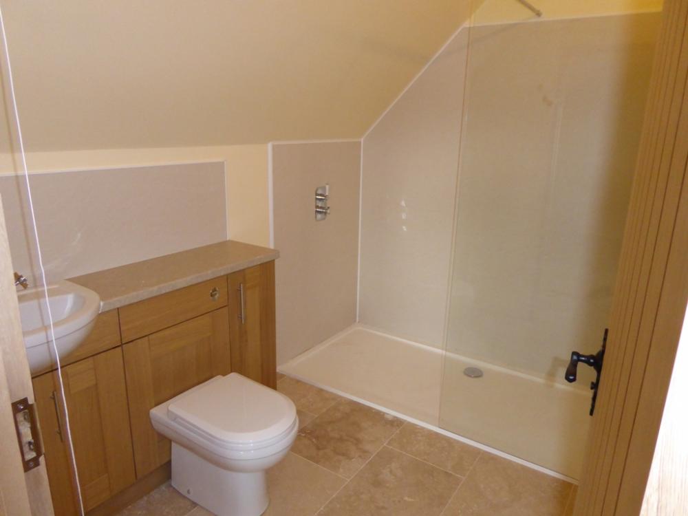
-
As above, the whole point of an un-vented cylinder is that it operates at high pressure, so is the same as a mains feed. A vented cylinder does reduce the pressure to the head from the cold water tank, but with a UVC there is no cold water tank, the cylinder is fed with mains pressure and sealed (with the rider that the incoming mains pressure must have a pressure regulating valve fitted for safety, to ensure that cylinder doesn't exceed it's rated working pressure if you live in an area with exceptionally high mains pressure).
-
I believe that one change has been that the DNO now is better at tying the N to a decent E at the transformer, so lowering the impedance and making TN-C-S as "good" an option as TT. If Ze (the earth impedance) is too high (above 0.35 ohms IIRC) for a TN-C-S arrangement you can always add a local earth rod in parallel with the earth (N) connection at the incomer to reduce the local earth impedance to a lower value (a good idea to have Ze as low as possible, in my view). Also, bear in mind that the critical factor as far as fault current is concerned is the fault loop impedance, Zs. It is Zs that will determine the maximum voltage rise at the PE/N of the RCD/RCBO and so determine the time taken to trip to some extent. In addition to sizing all the conductors appropriately (to reduce Zs) having as low as possible Ze at the incomer helps, as does having fatter and shorter cables after the incomer. The main issue with TN-C-S is if you have outbuildings with a long cable run from the incomer. In this instance, the additional cable impedance on either TN-C-S or TT (but it may be a bigger issue with TN-C-S because of the additional distance of the exported earth back to the sub-station transformer) can increase Zs at the remote end of the cable. You can always add an additional earth rod at any outbuilding to lower Ze locally and hence lower Zs on all the outlets in that outbuilding. This is what I've done. We have an incomer that is TN-C-S and because we have a fat (25mm²) three core SWA feed from there to the house, we have maintained a low Zs at the house. The garage has a 4mm² SWA feed, and although Zs remains within limits it is higher, because of the thinner cable, so the RCD in the garage could be a bit slower to act in the event of a marginal fault current. I fitted an earth rod and additional earth cable to reduce Ze at the garage CU, so reducing Zs and decreasing the fault operation time of the garage RCD. I did this solely because the garage will be used as a workshop, and there will be machine tools running in there, so the likelihood of there being a fault seemed to me to be a bit greater.
-
"remeasure" procurement contract issue
Jeremy Harris replied to ragg987's topic in General Construction Issues
My experience has been that bigger companies, in particular, tend to try it on a bit like this. We had quotes from some that were apparently reasonable, until you looked at all the things they had carefully missed out, and often the missed out items were not clear from the quote. When we were looking to place the ground works contract we had no end of problems like this, despite me having given every bidder a full and proper specification, including a volume of muckaway calculation from the topo survey versus the finished levels, including the excavation volumes for the retaining wall, house and garage foundation. The majority of the quotes we had "hid" the true muckaway cost (which we knew was going to be substantial). The company we went with in the end won the contract for two reasons. The first was they sent me their breakdown of costs from their QS and gave me his phone number and email address to discuss these with him directly if I wished, the second was that I liked the chap that ran the company and felt he was a decent and honest bloke (which he was). -
I still have the bit of bent bucket handle that was given to me by by the builder who was building the ground floor bedroom extension (for my father, who was by then a wheelchair user) with a single bedroom self-contained flat above for my grandmother (the mad Irish one). I was building a brick-built, curved, raised flower bed, for my father's roses, raised so he could reach them from his wheelchair. I remember building that wall very clearly, as I'd never done any bricklaying before. The builder gave me lots of instruction, and let me use his mixer, whilst my father sat outside watching me, whilst listening to the test match on the radio. Periodically he'd remind me that Churchill (of whom he was a great fan, to the extent of giving me the middle name Spencer............) could lay 400 bricks a day, and I would be lucky to lay 200 a day at the rate I was going. Mind you, I was about 13 years old at the time, so it was misuse of child labour, really. That means I've been carrying around that bit of polished, galvanised, bucket handle for over 50 years, and was using it only a week ago to point up some stone work.
-
"remeasure" procurement contract issue
Jeremy Harris replied to ragg987's topic in General Construction Issues
Re-Measurement Contracts are OK IF, and ONLY IF, you keep a running track of the variances on the submitted B of Q as the work progresses. In my view it's absolutely essential that such a contract includes provision for the contractor to submit a regular (say weekly or monthly) revised B of Q showing the variances, so that you are in a position to accept or account for them as they arise. From what you describe, it seems as if the B of Q was not revised during the contract, but only at the end, and now you are facing a nasty surprise. Legally, as long as the contractor can show that the final B of Q pricing is valid, and the items were included in the work, then you have to pay up. Personally I'd try and avoid a Re-Measurement Contract for domestic-scale work, as it's unlikely that there would be time for B of Q variances to be collated and agreed at sensible stages during the work, unless it was for a long-duration complete build. I'm of the view that for groundworks in particular, you are better going for a firm price contract, even though that carries the risk of being more expensive because of risk pricing, as at least you will know up front what the price will be. BTW, worth noting that a fixed price contract is not the same, and the final price of a fixed price contract may not be the agreed price, as variances for things like exchange rates are allowable. A firm price contract is a fixed price (confusing, I know) in contracting terms. I have a feeling that it is normal practice to put "unknown unknowns" as zero in the B of Q for a Re-Measurement Contract, and that legally this will be binding. I wish it weren't, because this doesn't give you a good outcome. You can certainly challenge the final B of Q, in fact I'd very definitely challenge it and ask for evidence for all the increases. You may well find that the contractor has played a bit fast and loose with their pricing, so, depending on the value involved you might want to consider getting a QS to go over the B of Q prices. -
One thing to watch is VAT receipts. I've spent the last few days collating our VAT reclaim and virtually no ebay sellers give a VAT receipt, and without the supplier's VAT number you cannot make a claim, I've found. I'd guess we've "lost" a fair bit of VAT as a consequence of this, as I bought quite a lot of electrical stuff (loads of Crabtree Starbreaker RCBOs, for example) from ebay. The same goes for Fastlec and TLC, they give you a VAT receipt most of the time, but I've had 2 or 3 receipts from both these companies that were emailed with no VAT number.