Jeremy Harris
-
Posts
26430 -
Joined
-
Last visited
-
Days Won
360
Everything posted by Jeremy Harris
-
Just be very clear what you're getting for your money, as often things can be very fuzzy when it comes to what is and is not included from any plans-drawing provider, be they and architect or architectural technician, or even some unqualified plans drawing service. Building regs approval may well be something you can do yourself, depending on the construction method you're using and any potentially complicated parts of the structure. I did our own building regs approval, the documents I submitted are all here: There are fees for building regs that aren't included in the quotes you've received, I believe, so these need to be taken into account as well.
-
Our ASHP has 1" BSPM fittings, but they are massively over-sized for a 7 kW maximum rated pump. The total flow through our UFH when it's running is only around 7.5 l/min, that's through all three loops, hence the reason for me saying that 15mm is enough and 22mm is really overkill, unless there are long pipe runs from the ASHP to the system. The thing to look at is the basic physics, what the temperature increase will be for a given power and a given flow rate. A 12 kW heat pump with a flow of 20 litres/minute will produce a temperature increase between the flow and return connections of 8.6 deg C at full power. In our case the maximum flow rate is around 7.5 l/min and the maximum temperature differential we see across the flow and return on an extremely cold (-7 or so deg C) day is about 4 deg C, so the heat pump is, in reality, only ever delivering around 2.1 kW, and that's only very rarely, most of the time the temperature differential between flow and return is 1 deg C or less, so the power is right down around 500W or so. If you needed to deliver 4 kW with a temperature differential of, say, 4 deg C to your heating on a very cold day, then the flow rate needed would be 14.2 l/min, well within the capability of 15mm pipe and DN15 valves, but fitting DN20 sized valves and 22mm pipe might be useful on long pipe runs.. You can easily work out the flow rate from the heat capacity of water (about 4200 joules per litre per deg), the power needed and the flow/return temperature differential (which will be lower than normal for a low output UFH system).
-
 You're right, a microfibre thing would be far better, as it would tend to retain the dust. I suspect a standard microfibre duster, tied with a thin cord around the centre, would be just about the right size to pull through a semi-rigid duct.
 -
Thinking about it, I can't see why a bit of cloth like a duster, with a cord tied around the middle, just like you'd do with an old school pull-through cleaning and oiling cloth, shouldn't work just as well on the small bore ducting systems.
-
I wasn't thinking of the bent offset connectors but the straight ones from McAlpine, I had to use one to get clearance, one of these: http://www.mcalpineplumbing.com/drain-connector-black-2506.html
-
When I compared the cost, because people were bleating on about in-roof being so much more expensive than on roof, I concluded that the complete GSE frame, fixings and flashing kit was just about exactly the same price as an on-roof frame kit, but that the in-roof system saved the cost of slates/tiles underneath and so was actually cheaper. Given that an in-roof system is a lot quicker and easier to fit than an on-roof system (no need to get inside the roof to secure through bolts etc) then PV installers should really be offering them at lower prices than they do.
-
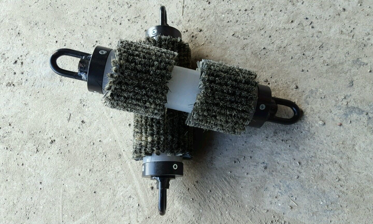
You can get short ones that go around tight bends, foam ones, "fluffy duster" one, the one above is a hard scrubber pig to get stuff off that's really well stuck on. Some of the lighter foam pigs can just be blown through ducts with compressed air, rather than blowing a pull cord through. TBH, I don't think I'd go to the expense of buying one, as a foam ball of around the right size for the duct, with a bit of plastic pipe stuck through the middle and a couple of large washers either side would be easy enough to knock up. With a bit of cord threaded through the middle, and knotted either side, you could run it back of forth through the duct, a bit like cleaning a gun with a pull-through.
-
That sums up my current experience - old school, retired (70 this week) inspector, brought back part time to help out, took one look at our build and said he didn't like it, as it "hadn't got any foundations" and things have gone down hill from there. PITA doesn't begin to describe it. I'm going around fitting water flow restrictors and taking photos of them, as requested, as he has done a 180 deg turn on the agreement I had that I didn't need water saving measures because we have our own water supply and treatment plant.......................
-
No one checks anything at all, it is entirely based on the information you provide. You just give a registered SAP assessor the as-built information, he/she produces the as-built SAP, lodges the EPC on the database and your BCO pulls it off that. You can do it any time before the final completion point, but it does need to be lodged on the database by a registered assessor before you'll get your completion certificate. You can do your own SAP calcs and send the completed data set to an assessor to lodge for you. I did this, but the saving was modest - the assessor still charged me £100 +VAT to lodge the report I'd produced. No one other than a registered assessor can access the government data base to lodge the report, so you're pretty much stitched up when it comes to trying to do the job yourself.
-
Can you use a small straight offset fitting to get around the problem? I had to fit one because my soil pipe stack coming out of the slab was very tight to the frame inside, and IIRC this gave me around 30mm or so of offset in a straight pipe connector, enough to be able to fit the soil pipe vertically with clips to fasten it to the wall. There also adjustable bends, like this: https://www.drainagesuperstore.co.uk/product/110mm-0-to-30-degree-adjustable-single-socket-bend.html that might help, I'm not quite sure what it is you need to do. There is another option that I have used in the past, although I'm not sure it's recommended practice, and that is to put some force on a length of 110mm pipe and then heat the outward facing side of the bit you need to to curve with a hot air gun, over a wide area. I've managed to induce a very gentle permanent bend in 110mm pipe like this, with no kinks. The key is to only heat the side that is going to stretch over the gentle bend, not the inside that's under compression, as that will make it kink. The BT Duct 56 that curves around under the bottom of our drive has a 2m long swept bend made like this - it worked well and retained a nice smooth bore.
-
Options for Utility Room Extension
Jeremy Harris replied to Ferdinand's topic in New House & Self Build Design
I'd say C has to be the low risk option, and putting in a beefier foundation isn't likely to add much at all to the cost (unless the ground conditions are difficult). The return on investment for the small extension will still probably be enough in terms of added value to get the cost back after a few years, assuming there's not another big crash in house prices coming along, and there doesn't seem to be any strong indicators that this will happen. -
Securing Bar Shower valves
Jeremy Harris replied to JanetE's topic in Bathrooms, Ensuites & Wetrooms
That's one of the problems with the ease of access to information we have via the web; we have no easy way of checking whether or not it's correct, unless we have a "Master Plumber" on hand to show us the errors! -
piling Piling; getting quotes and comparing them fairly
Jeremy Harris commented on ToughButterCup's blog entry in Salamander Cottage
I think there is a natural tendency to tunnel vision within the building business, generally. Solutions that have been used for hundreds of years (like piles) tend to looked at as the only solution. It's really quite rare to find anyone who stands back and looks at any problem from first principles, yet often doing that opens up a range of options that may not have been considered, some good, some not so good. For a foundation there are two key requirements, bearing stress on the ground underneath them and movement due to heave (and heave isn't just restricted to clay and moisture content - some places have to design for frost heave, too). The bearing stress limit for the ground is pretty easy to measure. The posh way is to use a penetrometer, the old school way is to use a bit of 2 x 2 and a lump hammer. For most purposes the old 2x2 test (still used by some building inspectors) is perfectly OK, as it tends to err on the conservative side and there aren't many foundations that need a max allowable ground bearing stress of greater than 100kN/m2, which is the rough result from that old school test. Bearing stress will change with moisture content for many types of ground, usually decreasing with increasing moisture content in the case of clay, but the fact that clay is a very effective aquatard has to be taken into account, so clay more than a foot of so down won't change much in moisture content in practice, unless it's just a thin clay band with an aquifer beneath and run-off above. Heave is more often than not the main problem with some types of clay, resulting from the relatively significant volume change with moisture content. My view is that it causes more imaginary than real concern, and most of the concern comes from the failure of shallow foundations within the London Clay basin. Many thousands of houses in and around London were built with shallow (often just corbelled brick) foundations, and these are particularly prone to heave damage. The result has been thousands of houses that have had to be underpinned and the horror stories that abound about building on clay, that aren't always really justified. All that's needed to remove the movement risk is to reduce the bearing stress down to a level that even wet clay will comfortably withstand, whilst providing an even load over a wide area and good surface drainage so that the clay moisture content stays fairly constant. This is why the deep ballast bed system works so well. The load spreads out into the ground at around 45 deg from the point of vertical load application, and the ballast provides a means of both spreading this load well and of draining the surface (land drains are put in around the periphery) so that the clay remains stable and well able to withstand the much reduced bearing stress. I estimated the bearing stress on the ground under our house foundation and it was around 20 kN/m2, which is very low, much lower than the typical bearing stress at the base of a traditional trench foundation -
We have 75mm OD (63mm ID) semi-rigid ducting. It's silent, the ducting creates no flow noise at all, any noise (only on full boost) is either from the terminal (pull the terminal off and the noise drops) or transmitted noise from the compressor in the MVHR when it's in cooling mode (as it's doing right now as I type this). The rule of thumb is to keep the duct flow velocity below 2.5 m/s, so if you have a high capacity requirement (kitchen extract is usually the biggest) then just double up on the duct runs to that terminal. All the terminal fittings I used will accept two ducts and have a blanking plate if only one is fitted. I doubled up on the run to the kitchen, but in practice I've found that I didn't really need to, as I've had to throttle that run back a lot to get the flow rate right and balance the system. On full boost I have some duct runs that are flowing at around 3.5 m/s, yet even these don't seem to generate duct flow noise, so I think the 2.5m/s guidance is a bit conservative. Ours is all HB+, but the duct seems identical to that sold under several different names, like Polypipe Domus, for example.
-
This is the only photo I can find quickly (from an ebay ad for duct pigs), but it gives an idea of how the things work:

-
Another cheap 12kW Kingspan Aeromax ASHP
Jeremy Harris replied to Stones's topic in Air Source Heat Pumps (ASHP)
IIRC, all of the functions that can be operated by dry contacts in that diagram I drew, can also be operated by the Command Unit. There's a lot of flexibility there, in terms of being able to programme when switched 240V is available from the ancillary relay bank in the ASHP, the one that controls the optional extras inside the red box at the bottom. You don't have to use those relays to control the functions shown as they are just programmable outputs that could be used for several different purposes. -
Have you looked at the low voltage Chinese ones? I know that a lot of Chinese stuff is not great, but I'm impressed with the quality of the DN20 ones I bought. What sort of flow rates do you have that necessitate a 28mm or 32mm valve? That's massive, as a 15mm valve will flow enough for around 10 kW or so at typical ASHP temperatures. I'm using 22mm (DN20) valves, but they are over-kill when I looked at the flow rate and worked out the pressure drop (after I'd bought a box of DN20 valves................). I could easily run our ASHP at full power through a 15mm (DN15) valve, with less flow restriction than there is in the 22mm corrugated coil inside the buffer tank. In fact the lack of flow restriction caused a small hiccup, as it seems the ASHP (like a boiler) needs to see some restriction in the circuit in order to confirm that the pump is running (what's often referred to as "pump kick" detection in boilers). It's the reason I have a thermally actuated valve on the UFH manifold, as that has enough flow resistance for the ASHP to reliably detect the pressure increase when the pump's running. My philosophy was that most valves fail (that's based on my experience of central heating valves having failed in every house with wet central heating we've owned) so there was merit in buying relatively cheap, but well-made, valves and keeping a stock of spares. For example, these £15 DN20 motorised 2 port valves will mate to 22mm pipe (via a compression to iron adapter), are cheap enough that you can use two to make a three way valve with common wiring (look at the wiring and switch options on the diagrams and you can see how to connect two together to work in opposition, from two wires or three), and you could buy a lot of them for the sort of money you're looking at: http://www.ebay.co.uk/itm/Motorized-Ball-Valve-Electrical-Valve-DN20-G3-4-12V-2-wire-3-wires-/201564641525?var=&hash=item2eee3058f5:m:mpjP6_x5zwaHxqXmPnZZWig If you needed 4 valves to make a double three way, then buying say, 12 valves would cost you £180 and you'd have two complete sets of spares. Mine have been working faultlessly for a year, and looking at them I strongly suspect that the only part that might fail is the motor, and that can be changed without touching the wet side.
-
The standard way to do it is to blow or pull a pig down each duct, either directly with compressed air, or indirectly by blowing a very light pull cord through and then pull the pig through. A web search will show all manner of foam and furry pigs for cleaning out ducts, and companies that will come and do it for you; search on pig or pigging and duct cleaning. I did think about leaving a thin cord inside every duct, so that it'd be easy to just tie a pig on, with a trailing cord to pull it back, and pull it through every few years. When I realised how easy it was to blow a bit of light cord down a duct with compressed air I decided not to bother, and only do it when I needed too.
-
I'm pretty sure the bonding requirement is as above, it really only applies when you have a large metal frame on the roof, and the idea is to ensure that everything sits at the same potential, to minimise the risk of shock. It's a bit like bonding the pipework in a house. Our current house has an MDPE water main, with a earth bonding wire connected to the stop cock just above it. There are similar bonding wires connecting the hot and cold pipes together all over the place (it's all copper). The idea was to keep all the metalwork that anyone can touch at the same potential, so you can't, for example, have the hot tap sitting at mains voltage (due to a fault) and the cold tap at earth potential - such a fault would cause enough current to flow to blow the fuse. With the advent of mandatory RCDs and plastic pipe fittings the need for bonding has pretty much gone for most situations, although there are still one or two places where it's needed, IIRC.
-
How not to run an incentive scheme
Jeremy Harris replied to a topic in Environmental Building Politics
The reason I ask is that our local police helo has an IR camera and goes around looking for hot sheds and houses, as often they find this is where all the cannabis is being grown................. -
How not to run an incentive scheme
Jeremy Harris replied to a topic in Environmental Building Politics
Out of interest, what do they grow in all these very warm sheds?................................ -
Our plasterer suggested I both cut all the pipes down to about the level of the plasterboard, so he could skim flat over the holes he'd cut in the boards, and also asked us to just coil up and record the down lighter positions, so the holes could be drilled after he'd skimmed. In my view anything that makes a blokes job easier is likely to either save you money or result in a better job (or, perhaps, both).
-
Another cheap 12kW Kingspan Aeromax ASHP
Jeremy Harris replied to Stones's topic in Air Source Heat Pumps (ASHP)
I better sit down and refresh my memory on all the settings then, as I remember looking at how the Command Unit might be used as a complete programmer/controller/thermostat back when Joe90 found a cheap ASHP, some time ago, but I haven't pulled the manuals out and had another look since. Getting the unit running to test it is easy, but ideally you want to fill it and connect it to something like a coil of pipe, so you can get a feel for how it works. You can make it run in cooling mode simply by putting a wire link between pins 3 and 6 on the ASHP dry contact connections (next to live wires, so caution is needed!) and you can make it run in heating mode by connecting a wire link from pin 3 and pin 6 and another link from pin 3 to pin 7. Pin 3 is the ground connection line for the control circuit, pin 6 is the "heat pump on" command line, pin 7 is the "heat or cool" command line. I drew this diagram that sort of explains what the dry contact connections do:
-
piling Piling; getting quotes and comparing them fairly
Jeremy Harris commented on ToughButterCup's blog entry in Salamander Cottage
If you can avoid using piles then I would, as not only is piling expensive, but is also adds cost in the form of the reinforced ring beam that joins the pile caps together and may create an access problem if you need a big rig. Tradition is at work here, as the traditional solutions for building on clay were either to use piles or to use a deep trench foundation with anti-heave measures (often foam to take out the effects of heave). The alternative solutions, of using another material to spread the load out and down, as detailed in that report (which is also available from Kore, now, I believe) are relatively new here in the UK for houses, but have been used for decades in other civil engineering works. For example, significant lengths of railway line across boggy ground has been laid on EPS, with ballast on top, and works very well. Hilliard Tanner has some good solutions for difficult ground, but it very much depends on the exact nature of the clay you're on. For example, if it's like London Clay, then piles or deep trenches are often the only solution, because of the relatively high heave potential. If you're on other forms of clay, then this may not be an issue at all; we're on hard gault clay, and that doesn't heave at all to any measurable degree, so an ordinary slab works OK. On the other hand, the gault clay we're on does shear easily when wet, so our retaining wall needed a large shear key at the base of the foundations, to prevent the base from sliding out under the side load. -
piling Piling: talking to the contractors; (now) not so clueless of Lancaster
Jeremy Harris commented on ToughButterCup's blog entry in Salamander Cottage
Time and time again throughout our build a remark made by an army chap that worked for me years ago comes to mind, "Time spent on reconnaissance is never wasted". I also became absolutely convinced that very few companies treated self-builders seriously, especially on the civil engineering side (and we had a LOT of that on our site). As an example, I'd done a fair bit of research on gravity retaining walls, how they worked, how to calculate the various loads acting on them, etc, as originally I was thinking of building either a gabion or Permacrib retaining wall. In the end, the wishes of the neighbour to have stone boundary wall on top ruled those systems out, so I had to get a structural engineer to design a vertical concrete retaining wall. In fact I did the design first, to see what the cost would be, before going out to both retaining wall specialists and a few local structural engineers for quotes (I already had a full hydrogeological report detailing the strata beneath the site). Quotes from SEs ranged from around £360 from a local chap, for a design, calculations, drawings, steel spec, etc (backed by his professional indemnity cover) to £1200 for an "initial sketch design, plus site visits at £250 each, as required, plus additional fees for steel specifications and working drawings" from another local firm. Needless to say I rang the cheapest chap, he seemed a very competent and helpful bloke, said he knew the site well, as he'd already done some preliminary designs for a motor home secure parking area on there (for the previous owner). He got the job, and produced a nice set of hand drawn sections, specifications, calculations and a steel specification table (clearly "old school", as he didn't even use email.........). Out of politeness I emailed all those who'd quoted but not won the job to tell them. The most expensive firm, emailed me a questionaire, asking if I'd fill it in for feedback as to why they'd lost the job. I did this, fairly and honestly, with the exception that they asked for the names and prices of the other quotes. I thought it unethical to give names, but did agree to give approximate prices. First I got a fairly rude phone call from a lady in their office saying that the other companies were all going to do a poor job (the second most expensive quote was around £700, IIRC) and then a day later I had one of the partners in the firm ring me, again telling me that I was taking a significant risk by not using them. At this point I told him that I had double checked all the calculations, using the method in BS8002, BS5628 and Eurocode 7 and found them to be correct, so what was his problem? He immediately changed tack and said "Why didn't you tell us that you had already done the engineering calculations?", from which I assumed that he originally thought I was a self-builder numptie that could be hoodwinked into paying three times the price.....................- 2 comments
-
- 1
-

-
- project management
- dealing with experts
- (and 2 more)