Jeremy Harris
-
Posts
26430 -
Joined
-
Last visited
-
Days Won
360
Everything posted by Jeremy Harris
-
Looks like this is a really old thread that's been resurrected from last year for some reason.
-
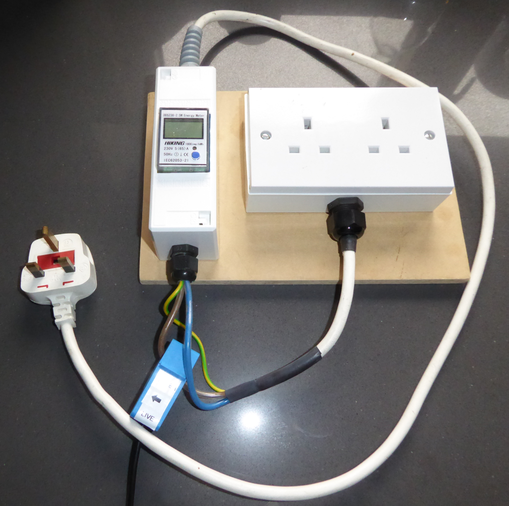
The only way to accurately know the electrical input is to measure it. As the power factor (PF) may well not be unity for a heat pump, measuring just voltage and current independently may not give an accurate indication of input power. Fitting an simple energy meter, one that has a power display as well as energy, to the supply to the heat pump will give an accurate measure of input power. Small, DIN rail mount energy meters like this are fairly cheap and seem to work well. I have one fitted in a small enclosure on a test lead that I made up: I have a similar one connected in the supply to our air source heat pump, and find it pretty useful. It not only gives the energy (in kWh) that the heat pump uses, but also displays voltage, current, power factor and instantaneous power. I think the one above cost about £15 or so.

-
OK, I should have added that the discrimination criteria includes time as well as current, but in general time delay RCDs/RCBOs aren't that common in a domestic installation, are they? I stand by the statement that it isn't good practice to daisy chain RCDs/RCBOs.
-
Some RCBOs do have an earth lead, so may cause an imbalance that can trip upstream RCDs. Off the top of my head I know that single pole Crabtree Starbreaker RCBOs have an earth lead, some other makes do, to.
-
Really because of the nuisance caused when an upstream RCD/RCBO trips as much as anything else. There's no added protection from daisy chaining RCDs/RCBOs without discrimination between trip currents. If there is no discrimination, then upstream RCDs/RCBOs may trip when the downstream ones are tested. It's usually fine. My garage feed is a run of 6mm² SWA protected at the upstream end with a 40 A DP MCB. At the garage CU I have an RCD feeding MCBs for the various sub-circuits, so there's adequate residual current protection on every garage circuit, and if there is an earth fault, the RCD in the garage is the one that trips. RCD protection is required at the user end of any circuit, located somewhere upstream of the outlet/lamp/etc, so they are all adequately protected, but there's no real need to RCD protect SWA cable runs leading to a sub-main CU, all that needs is over-current protection usually. If the cable isn't armoured, then fitting a 100mA RCD/RCBO at the upstream end makes sense and provides the required trip current discrimination.
-
You shouldn't daisy chain earth leakage devices, be they RCDs or RCBOs, without ensuring that there is an adequate difference in the trip current. For example, a 100 mA trip current RCD/RCBO upstream of 30 mA RCDs/RCBOs is fine, as there is current discrimination and the downstream ones will trip first. In your case, as you have (most probably) a 30 mA trip current RCBO upstream of the installation, that is providing adequate earth leakage protection for everything downstream. All that should be fitted down stream are over-current protection devices, fuses or MCBs, not any device that includes residual current/earth leakage fault protection. The exception to this is when a downstream installation is connected as a TT island, with it's own earth electrode, when it needs an RCD/RCBO.
-
Every hot water cylinder I've ever had has had at least one temperature display, two have had three, top, centre and bottom. Even our buffer tank has two temperature sensors, so that I can glance at a display and quickly see how charged it is.
-
Not sure it matters much, TBH. Mine is home made, and works just fine with the Sunamp, and before running the Sunamp Uniq we have now it also worked fine with a Sunamp PV. Before that the same unit worked with an immersion heater in a thermal store. All the Sunamp needs is power, and it's not fussy where that power comes from. as the power just flows through the contactor in the control box direct to the heating element, there's nothing smart inside the control box that even senses that power. It looks as if there was an issue with the Eddi that meant that it was not providing power to the Sunamp in this case. By the same token, lots of EV owners have also had issues with the Eddi controlling the Zappi charge point. I'm far from convinced that some of these "smart" solutions are a good option for stuff that is critical, like having reliable hot water, or reliably charging a car.
-
Just needs a low temperature coil. One fitted with a "solar" coil will usually, be OK, but quite a few manufacturers now offer cylinders with a heat pump coil. The difference is that a UVC intended for use with a boiler will have a coil that works OK with a high flow temperature, around 55°C to 65°C, whereas for use with a heat pump the coil needs to work OK at a lower temperature, typically around 45°C to 50°C. The difference is that the low temperature coil will be physically larger inside the cylinder, to allow it to work efficiently at a lower temperature.
-
The 9 kWh Sunamp takes around 10 kWh to fully charge, and actually stores around 10 kWh of useful heat, as the 9 kWh rating seems to just be for the energy stored by the phase change of the PCM. There's about another 1 kWh stored by the hot PCM when it's all melted and sitting at ~60°C or so. This means that in regular daily use you can get around 10 kWh out of a 9 kWh rated Sunamp, especially if you start to draw off hot water shortly after it has completed charging. Be very interested in whatever Sunamp come up with to indicate state of charge. It's a PITA not knowing what the thing is doing, or what state it's in. It shouldn't be too hard, as they already have a string of thermistors running vertically down inside the thing, so the control system knows the temperature variation from top to bottom already, it just doesn't display it.
-
 Yes, the thing is definitely fully charged, as when it is the pipe outlet at the top feels hotter than normal. Surprised me a lot, TBH, as I only went to look at it to take that 'photo, and I expected the "calling for heat" LED to be on. Had to check the generation data to be sure.
 -
It's as annoying as hell not having that information visible. I was surprised, when I took that photo a short while ago, to find that the "calling for heat" LED was off. That means that our PV system must have provided around 6 kWh of charge to the Sunamp this morning, which is pretty unusual for this time of the year.
-
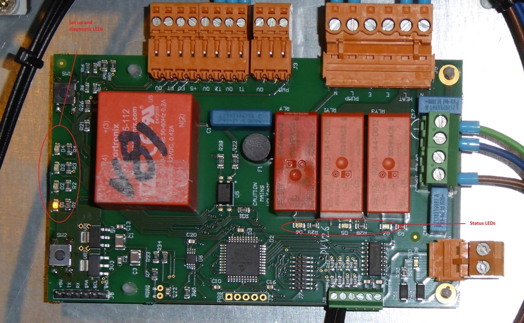
The vertical row LEDs on the left aren't much use for day to day monitoring, unfortunately, they are really only any use when setting the unit up and checking to see whether it's in cold start mode. The most useful LED is the one over on the right, under the relay that switches the main contactor on and off, as that shows whether the unit is "calling for heat" (each of the relays has a status LED underneath it, in a horizontal row). That LED is the reason my unit is still sat with it's lid off (not recommended - it exposes mains voltage connections - just don't poke your fingers inside). I glance at it to check whether or not the unit is ready to accept charge or not, something that is extremely useful to be able to see on a regular basis. Here's a photo (it's the centre one of the three on the right that is most useful to see):

-
Perhaps worth swapping the contactor over, just to eliminate it if nothing else, but worth doing some checks first. The fact that the contactor is clicking, yet the unit isn't heating up, indicates that there's no voltage getting to the heating element. Given that the Finder contactor in my unit gave up the ghost after two or three months, and that the symptoms when ours failed were exactly the same as yours, makes me suspect that you may have the same fault. The contactor is a standard 1 module wide DIN mount one, and easily swapped. The other thing to check is that the incoming power to the control box (the 16 A rated supply, not the low current control supply) is actually there. Checking the voltages at the contactor should prove that. Terminals 1 and 3 at the top should have the incoming supply voltage on them all the time the unit is being powered (in your case by the boost function I suspect). Terminals 2 and 4 at the bottom should have power on them whenever the contactor has closed. If you have access to a suitable meter and feel competent to use it, then checking the voltage at these points would give a very good insight into what may be going on.
-
Whip the lid off the control box and see if your unit has a contactor with the maker's name Finder on it, towards the lower right corner. If it has, then it's possible that's failed, as ours did.
-
The thing at the left of the photo is the over-temp cut-out. If it's tripped then you can tell when you try to reset it by pushing it in, as it will click. If it doesn't click it hasn't tripped, in which case it seems likely that the Finder contactor in the control box may have failed, as ours did. I had the same problem with Sunamp wanting to send a complete replacement unit. As ours is upstairs, and a complete nightmare to get up the stairs, I managed to persuade them to just send a replacement control box and sensor string, which seems to have done the job.
-
G3 or G4 filter?
Jeremy Harris replied to cwr's topic in Mechanical Ventilation with Heat Recovery (MVHR)
I've been getting custom made filters from Jasun Envirocare. They make filters and frames to any size you like, and were a lot cheaper than buying from the UK Genvex supplier. -
It's a pity that this myth that a passive house will need no heating is still being promulgated. It was never the case, and the PassivHaus Institut have always allowed for some heating being required in even a certified PassivHaus. Our's isn't certified, but meets the requirements set by the PHI, yet we very definitely need heating for maybe three to four months of the year. Not a lot, but the house would be damned cold without it. We manage to heat the house just using UFH run during the E7 period, and that seems to work fine. The concrete slab has the UFH pipes set into it, so acts as a giant storage heater. We only use our 9 kWh Sunamp for hot water, and TBH it wouldn't have enough capacity to be able to do anything else. There are just the two of us, and we use around 2/3rds of the capacity of the Sunamp each day, just to run showers etc. If we have guests, we need to boost the Sunamp for an hour or so between showers, in order to give the additional hot water needed.
-
Exactly as mentioned in the first reply in this thread, then...
-
Your unit will be near-identical to mine, as I thought it was the same vintage, just from the description you gave. The eDual has slight differences inside the control box, but your description of the fault sounds identical to the fault we had around this time last year. I'm also near-certain that your control box will have the same Finder contactor as was in ours.
-
Nick, from the description given, the Sunamp is powered up and seems to be stuck in cold start mode, with the contactor clicking on and off, but the heating element not actually heating the PCM. I don't think this can be related to the Eddi or the UFH, if the Sunamp is just stuck for hours in what sounds to me like cold start mode, especially as it's being powered by being switched to boost mode, which should just apply power to the Sunamp, regardless of any other settings. This is identical to the symptoms we had when the Finder contactor failed, and Simon's units is a similar vintage to ours, I think. The unit just sat there clicking the contactor "on" and off, but no power was getting to the heating element. Given that there's also no "crunching crisp packet" sounds from the Sunamp, it seems very much as if there's no power getting to the heating element.
-
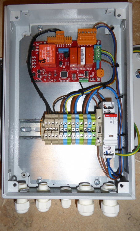
If you open up the control box and it is the version with the Finder contactor at the lower right corner, then if you have a meter you can check whether the contactor is actually working by checking to see if there is power on the two terminals at the bottom, should be marked 2 and 4, when the contactor is on. If there is power on those two terminals, going on and off as the contactor clicks, then the problem is most probably downstream of there, either the heating element, the over-temperature cut-out or perhaps a wiring problem. This is a photo I've just taken of our old control box, with the ABB contactor that I fitted to replace the faulty Finder one. It's probably a slightly different layout to yours, but I'm pretty sure they all have the contactor/relay at the lower right side:
-
Temporary heat source for UFH: Willis heaters
Jeremy Harris commented on oranjeboom's blog entry in Kentish RenoExtension
When we bought the house in Portpatrick that had a genuine Willis heater (an "Economiser") the installation instructions were left behind by the previous owner. This would have been around 1994. The diagram was a line drawing that was identical to that diagram posted above. As mentioned before, I think the issue is that these things are now made by several different companies, and it doesn't even look as if Willis Heating still make them. The companies that are now making them seem to assume that people will know how to fit them, probably not that sensible given that some are now using them for purposes that Willis never intended back when they first designed them. -
The clicking noise is most probably the relay turning on and off when the unit is in cold start mode. It needs to be continuously powered to complete the cold start cycle, as it pulses power on and off to the heating element in order to melt the solid PCM around it without risk of overheating. Once the temperature at the base of the unit is high enough to indicate to the control unit that the PCM around the element has all melted, the unit will keep the heating element on until the unit is fully charged. There are other clues to listen for. When doing a cold start there will be a crackling noise, a bit like a crushed up crisp packet, whilst the heating element is on. If you are not hearing this, and the unit is staying in cold start mode, then this indicates that the heating element is not getting hot. There are two things to check, as this exact problem happened with our unit. Firstly, check that the over-temperature cut out hasn't tripped. Isolate the power, test to make sure the power is off, and then unscrew the cover at the left side of the unit at the bottom. Behind this are the connections to the heating element, and at the far left of the opening there is a reset button. If this clicks when pressed in, then it has tripped. The other failure mode (and the one we experienced) is the contactor in the control box. If your unit has a Finder contactor at the lower right side of the DIN rail inside the control box there there is a chance this has failed. When ours failed it was still clicking on and off, but the contacts were stuck open. I replaced it with an ABB single module 20 A contactor that I happened to have in stock and the unit came back to life. At the time, Sunamp were just not responding to complaints, and didn't even acknowledge this failure, let alone do anything about it. Our unit was about 3 months old when the Finder contactor failed. Sunamp have since changed the design of the control unit, and after much badgering they supplied me with a complete new control box. I noted that this new control box has a different type of power relay, so my guess is that they may know full well about the poor reliability of the Finder units. If you get stuck, and find that it is the contactor that has failed, then I'm not far from Somerset and I still have the ABB contactor I used to fix our old control box.
-
Temporary heat source for UFH: Willis heaters
Jeremy Harris commented on oranjeboom's blog entry in Kentish RenoExtension
I can assure you that it was indeed designed to be fitted with the electrical connections at the bottom. There must be many thousands of these in use in NI, all fitted the right way up. The only cases I've seen of people fitting them upside down are on this forum and it's predecessor, so it seems to be something that has sprung up here. We have a few members here from NI, and I'm sure they will confirm that they are always fitted the right way up over there, as shown in that diagram I posted above that is a copy of the original Willis instructions.