

Jeremy Harris
-
Posts
26430 -
Joined
-
Last visited
-
Days Won
360
Everything posted by Jeremy Harris
-
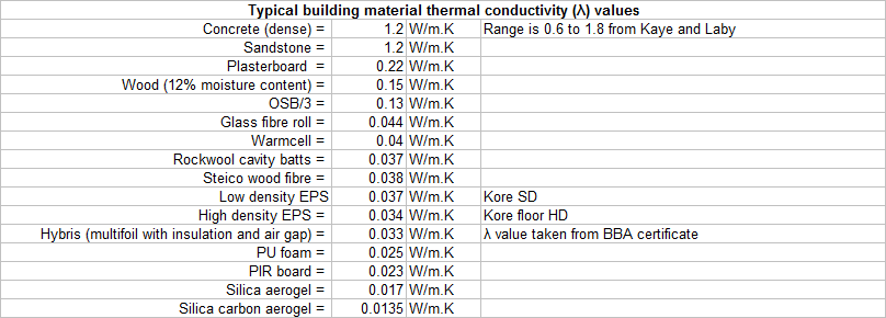
Depends very much on the moisture content, I believe. I used a value of 0.15 W/m.K for dry wood when I was looking at heat loss, a value that I got from here: https://www.engineeringtoolbox.com/thermal-conductivity-d_429.html I think (that gives a value of 0.147 W/m.K for dry wood across the grain). I collected together some lambda values for building materials in this list, that may help:
-

Electric boiler confusion, and EV charging.
Jeremy Harris replied to AliG's topic in Housing Politics
Not sure what the problem is with domestic 3 phase smart metering, TBH. Might be something to do with the meter specs, perhaps a bit like the SMETS1/SMETS2 fiasco. Could also be that the data network system for commercial metering is different to that for domestic metering. It does seem to be a consistent issue, though, as the inability for suppliers to provide smart metering to 3 phase domestic consumers seems to be a long standing one. -
Electric boiler confusion, and EV charging.
Jeremy Harris replied to AliG's topic in Housing Politics
The reason for this is that there are no smart 3 phase meters available at the moment, I believe. This means that you're probably out of luck for any tariff that needs a smart meter. Not sure what the Bulb Varifair E7 tariff is in your neck of the woods, but we've been on it for a year now and it's still best value for us. If it looks OK for you then you could use my code and we both get £50 out of it. . . -
Adding a timer to an EV charging point.
Jeremy Harris replied to newhome's topic in Electrics - Other
Me too. . . -
Adding a timer to an EV charging point.
Jeremy Harris replied to newhome's topic in Electrics - Other
Thanks, it looks like the changes proposed to Section 722.411.4.1(iv) will enable one of the magic box solutions to be used instead of an earth electrode. That bit is worded almost as if the manufacturer of the device (matt-e) wrote it. . . It also looks as if they intend to leave the door open for other protection methods, from the wording of 722.411.4.1(v). Not wholly sure this is as safe as using an earth electrode, TBH, as they are assuming the same degree of reliability for the voltage sensing device as for an earth electrode and its associated connections. Given that we know that protection devices can, and do, fail in ways that renders them inoperative, it seems that there is still a risk, especially as there's nothing in there about how these devices can be tested. -
Adding a timer to an EV charging point.
Jeremy Harris replied to newhome's topic in Electrics - Other
Trading Standards can't even make a tiny dent in the vast number of dangerous bits of kit being imported to the UK, more often than not with fake approval marks, so I doubt they are going to have the resources to go after car manufacturers (and charge point manufacturers) who are selling stuff that's non-compliant. A bigger issue, in terms of safety, is charge point installers not installing charge points in accordance with the provisions of Section 722 of BS7671:2018. There are a LOT of non-compliant installations, as installers seem very keen to avoid having to install an earth electrode, and are using all sorts of dodges to pretend this isn't needed. You and I know only full well about the risk a PEN fault presents to a big lump of metal outside, connected to a TN_C-S/PME provided PE presents, but nevertheless it's still fairly common to find that installers are ignoring this, or using some sort of magic box to pretend that an earth electrode isn't required. -
Adding a timer to an EV charging point.
Jeremy Harris replied to newhome's topic in Electrics - Other
The standards have been in place for a while now, and haven't really changed a great deal from the original J1772 standard that first saw the light of day over 20 years ago. The issue seems to be that car manufacturers aren't consistent in their interpretation of the standard, and don't stick to it rigidly enough. For example, the control pilot is an analogue signal, with a 1k source impedance. Initially this signal sits at +12 VDC, and when a car is plugged in, the car loads this line down, reducing the voltage to +9 VDC. The charge point senses this change, and starts a +/-12 V pulse train on the control pilot, at 1 kHz, with the duty cycle indicating to the car the maximum current that is available (the advertised current). The car then signals to the charge point that it's ready to accept charge, by loading the control pilot further, so that the positive going part of the pulse train is loaded down to 6 V (the negative going part has a diode to PE in the car, so still swings to -12 V). Some cars ignore the negative going part of the pulse train (which is there for safety reasons) and will work with a charge point that only sends out a 0 V to +12 V control pilot. Some cars work properly and require the -12 V part of the control pilot signal to be there. The car is supposed to wait indefinitely for the charge point to turn on power after the car has signalled its acceptance of the advertised current, but at least one car doesn't (the model I have). If all manufacturers rigorously implemented the spec, as defined in IEC61851 then I don't think there would be any problems. -
Adding a timer to an EV charging point.
Jeremy Harris replied to newhome's topic in Electrics - Other
Yes, there is, but it's not at all easy to break into this in a commercial charge point to do this. My charge point is home made, and includes an enable port, that allows the control pilot connection to the car to correctly signal that charge power is, or is not, available. The standard allows for this, and cars are supposed to stick to the protocol, but not all do. My charge point has three modes, selectable via a three way switch, off, on and timed. In the timed position the charge point signals to the car that charge power is available only during the E7 off peak period. That worked perfectly with both the Prius Plug In and the BMW i3, but is completely ignored by the Tesla Model 3, as the Model 3 doesn't seem to follow the protocol, and refuses to wake up and start charging when the charge point signals that power is available. The advantage of doing it the proper way, like this, is that the timer is only working with logic levels, not switching power, plus the charge point maintains the right control pilot signal, so the car should know that it is connected, but that no charge current is being advertised, so it should wait for an indefinite period for the control pilot to start advertising. -
Adding a timer to an EV charging point.
Jeremy Harris replied to newhome's topic in Electrics - Other
It's not easy to just fit a timer to a charge point, for a few reasons. The first one is that the current being switched is pretty high (30 A in your case, could be up to 32 A) and that means using a time switch that's capable of handling that sort of current, and they aren't that common or cheap. Another potential issue is the way that the car and charge point interact. This varies from one EV to another, but some need the control pilot signal from the charge point to be active as soon as the lead is plugged in, so the car can adjust its onboard charger to the advertised current, before any charge timing can happen. Other EVs will either just accept a charge point going live whilst plugged in and start charging, throw a charging error if this happens or refuse to charge (mine does the latter, it point blank refuses to charge if the charge point is run on a time switch). In theory timed charging like this should work OK, but theory and practice are often different when it comes to the foibles of some EVs. Was your charge point installed with an OLEV, or other, grant? If it wasn't, then you may be able to get it swapped over for a smart charge point that offers scheduled, or tariff tracking, charging, (if your car will accept this). All new charge points that are partially grant funded have to be smart, so they can all be scheduled etc. In your case there there are two grants available, up to £500 from OLEV plus £300 from a Scottish grant initiative. You can probably do a test to see how your car responds to the charge point going live after being plugged in, by turning off the circuit breaker (with the car unplugged), plugging the car in, waiting for maybe half an hour to be sure the car has fully shut down it's onboard systems, then switching the circuit breaker on. This is safe, as turning the power on initially won't draw a high current, as the charge point has to boot up and then do the control pilot handshake with the car, before it will turn on its internal contactor. If the car charges OK doing this, then you have the option of adding a time switch and contactor to the circuit supplying the charge point. This is probably the cheapest option overall. -
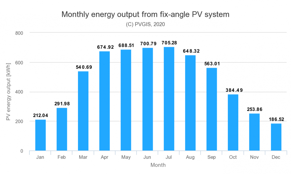
Changing electricity supplier is getting to be a bit of a minefield now, especially with some of the more complex ToU tariffs. I keep a spreadsheet of our usage profile and the latest tariffs from suppliers in this area, and in the last six months or so it's becoming clear that the usual price comparison sites are struggling to give accurate recommendations for some tariffs. Our house is all-electric (electric heating, cooling, hot water and charging my car), and we're paying about £48/month for electricity, so a bit under £600/year. We get back about £1,000 a year for the electricity we generate, though, in FiT and export payments, so we have no real energy bill to pay. I accept that the FiT payment we get is a bit of a fiddle, as it was an incentive to get us to fit the solar panels we have built in to our roof, but nevertheless it was on offer and I wasn't going to turn it down. The 25 solar panels (6.25 kWp) provide roughly 60% of our annual hot water, with the rest coming from using off-peak Economy 7 electricity overnight. We find that the electricity generation from the more or less South facing solar panel array drops off a cliff in October and then picks up again about March, so we have four or five months with very little solar power. The data from PVGIS ( https://re.jrc.ec.europa.eu/pvg_tools/en/tools.html ) is pretty accurate, and matches our pattern of generation fairly well:
-
It's really hard to do high power stuff, like warming water and space heating, at 12 V. Might be an idea to take a look at the Navitron forum ( https://www.navitron.org.uk/forum/ ), as there are a few there who are totally off grid, plus some who are partially off grid, and have a fair bit of experience of using low voltage DC. I'm pretty sure that most end up running systems at around 48 V, really to overcome the problems caused by cable power loss as much as anything else, but they may still be good source of expertise on low voltage stuff.
-
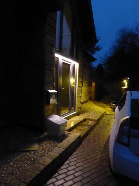
The main issue with using 12 V for lighting used to be, and perhaps still is to some extent, the power loss caused by the voltage drop in cabling. To some extent this has been alleviated a bit by the lower current demand from LED lighting, but if you want a reasonable amount of light the current at 12 V can still be pretty high. For example, I've used quite a lot of 12 V LED strip lighting, some of it powered by solar and battery systems. To get a reasonable light level I found that I needed to use 5630 LED strip that uses around 12W/m. The ~2m length above our front door draws about 2 A, and although bright enough, it's not massively bright (a fair bit of light in this photo is coming from the 10 W LED floodlight behind the car): In this case the cable run is very short, you can just make out the battery box and solar panel to the left of the strip light, so voltage drop wasn't a problem. However, when you have a fair area to light up, it's easy to get to the point where heavy cables need to be used to minimise the voltage drop and associated power loss. I originally use this same LED strip in my garage, as four 5m lengths, but ran into problems as each strip was drawing about 5 A at 12 V, so 20 A in total, and the losses in the wiring were starting to get a bit high. I ended up switching to tubular mains LED lights, just to get around the problems caused by this. Increasing the battery voltage to match the voltage of standard solar panels helps a bit, and is probably a sensible compromise. Standard solar panels have an maximum power voltage of around 30 V, so with a suitable MPPT and charge controller can charge a 24 V battery system OK. Using 24 V rather than 12 V halves the current and reduces the power loss in the wiring to one quarter of that from a 12 V system for a given power, so makes a significant improvement. It's also usually fairly easy to find bargains for this size of panel, as they are the ones used on practically all domestic scale PV systems.
-
I agree, but there is still only so much anyone can practically do. All our heating and hot water is already load shifted, as is charging my car and charging the battery pack that runs the network stuff in the house. On dull days the washing machine is also timed to run overnight. The rest is either on 24/7, like the sewage treatment plant, water UV disinfection unit and MVHR, or cannot practically be load shifted, like cooking, watching TV or running the water pump when we need water. Because our house is all-electric, we can probably load shift a fair bit more than most, but I still can't get a variable rate tariff like Agile to work well.
-
The main problem I've hit is that there is only so much load shifting that's practical. We're at that limit, in that as much as possible has been switched to overnight, and there's nothing more of any significance that can be time shifted. I would guess that many consumers just won't wish to, won't know how to, or just can't be bothered with time shifting usage to fit a variable ToU tariff. Experience seems to have shown that few consumers really make optimum use of simple long standing ToU tariffs, like E7.
-
I'm pretty sure, from watching the rates, that what's happening at the moment isn't profitable. These smaller suppliers are working on very tight margins and relying on continued fast growth in their customer base to survive (hence the attractive referral incentives they are offering - they need to grow their customer base to survive). I have a sneaking suspicion that their business model is a bit like a pyramid scheme, that may well just fail at any time. The track record for smaller, more innovative, energy suppliers is not at all good, many have gone to the wall in the past couple of years. The biggest problem that they will face when more of their competitors jump on to the flexible pricing bandwagon is that consumers will find it harder and harder to compare tariffs. This is already clear with the big comparison sites, as they are unable to fairly compare the flexible ToU tariffs with the offerings from other suppliers. I've been tracking both Go and Agile against our Bulb Varifair E7 tariff, and so far both Go and Agile are significantly more costly, even in winter, when we buy more electricity than at any other time of the year. This comparison is only possible because I have an accurate (6 minute sampling period) record of our actual energy consumption. Anyone who doesn't have accurate data to at least half hourly sampling just is not going to be able to compare tariffs at all easily.
-
Welcome @arg, I believe we may have "met" elsewhere in cyberspace. I believe that the PCM 34 units may be available again, after having suffered some teething troubles. @Barney12 may be able to shed more light on this. We have a 9 kWh PCM 58 unit, that now works very well, after a shaky start with a poorly designed control system. Our PCM58 unit provides all our hot water, with the majority of the energy coming from our PV system, boosted by E7 overnight, if needed. Sunamp seem to working with some resellers who aren't always as transparent or helpful as they might be, but I'm pretty sure you can still deal directly with them. I bought both our original Sunamp PV and the Sunamp UniQ we have now, directly from Sunamp, but I'm aware that they have recently contracted with maybe three or four different resellers, so I'm not 100% sure if they are still selling directly or not.
-
From a quick look, it seems that all Part G3 mentions is the installation requirements. In general there's an over riding requirement to comply with the manufacturer's instructions though, and from what I've managed to dig out earlier this evening, these all seem to mandate an annual service. TBH, I thought that Part G3 mandated annual servicing, too, but if it does then I've not been able to find it.
-
I spent a happy hour draining down our water system accumulators (which are really just the same as very large expansion vessels) this afternoon, and refilling them with air to the right pressure. When doing this I noticed that the label on one mentions the need to check the pre-charge (air) pressure at least every six months. One of the big ones had lost a lot of air, and it took my little 1 1/2hp compressor about ten minutes to get it back up to the 2 bar pre-charge pressure. It looks as if the Schrader valve may well have a very slow leak, so I'm going to replace them all with new ones as well as fit some metal dust caps, with decent rubber seals. I'd not checked these for about 3 years, so it's my fault they have lost a fair bit of air, but it did make me wonder what the recommendations were for checking the expansion vessel on a UVC were. The answer seems to be that all the UK UVC manufacturers I could find, that published servicing details, mandate that their products be serviced annually. Many also make it clear that this annual servicing is required in order for the extended warranty to be valid. My guess is that one of the main things checked during a service will be the expansion vessel pre-charge.
-
One thing I now regret is not having more of our windows non-opening. At least 50% of our windows never need to be opened, and so would have been better as fixed ones. It was a detail that I just didn't pick up when getting window quotes. The only issue with non-opening windows is really one of appearance, as if next to an opening pane they can look a bit odd, because of the narrower frame. Having said that, we don't have any air leaks around the windows, so it's not an issue. It just means that cluster flies have somewhere to gather in the tiny gaps around the outside of each casement.
-
Powerline WiFi options?
Jeremy Harris replied to Jeremy Harris's topic in Networks, AV, Security & Automation
That makes sense. I used to have the DHCP range limited, with a block of reserved IP for the fixed stuff that I might be playing with, like Raspberry Pi's, and the printer, which for some oddball reason only seems to work reliably with a fixed IP. I forgot to set this up in the rush to get the thing up and running yesterday. I'll need to go in and do this some time, as well as set two or three IPs in the fixed block so that they use the Pi Hole as the DNS server. I used to have the Pi Hole set as the DNS server for the whole LAN, but it seems to cause issues for SWMBO, who, for some reason, likes to see all the adverts. . . -
Some pressure reducing valves do have a pressure gauge. The one I originally fitted (before I changed things around so it wasn't needed) had one. Looked like this:
-
I deliberately hunted around and found both a 16 port switch and a router than don't have fans. I've two PCs here that don't have fans either. I even get annoyed by the fan in my laptop, and its replacement is going to be a fanless model.
-
@Alslo, I've just updated the spreadsheet link in that old post that @joth linked to, as back when I posted that the forum wouldn't accept spreadsheet files and now it does. Hopefully the spreadsheet should be fairly easy to work through, the hardest part might be getting local temperature data for your location.
-
If the expansion vessel loses its air charge, then the pressure inside the UVC can rise when it heats up. The expansion vessel is there to do as its name suggests, and allow for this expansion, as water is (as near as dammit) incompressible. Might also be worth checking that the pressure relief valve is fitted and working OK, as if the pressure in the UVC gets too high that is supposed to open to reduce the pressure to a safe level. It's there as a backup for the expansion vessel losing its charge, really, or, perhaps, if the pressure reducing valve on the inlet side fails.
-
My experience has been that expansion tanks need checking annually. We have a few here, including three big ones (two 300 litre and a 100 litre) in the water system. I noticed that the water pump was cycling on and off more rapidly than it should, checked and found all three tanks very low on air pressure. At a guess I've not checked them for maybe three years, and during that time they've gradually lost charge. One thing I noticed on the UFH expansion tank was that the Schrader valve didn't always seal as it should. I changed it for a new one, and as an additional precaution fitted a metal valve cap with a rubber seal. I remember reading somewhere, years ago, that a Schrader valve was only considered to be a secondary seal, and that the primary seal is the dust cap. I'm going to pick up some new metal dust caps this weekend and go around replacing the plastic ones, on the tanks, in the hope that it may help them maintain pressure for longer.


