

Jeremy Harris
-
Posts
26430 -
Joined
-
Last visited
-
Days Won
360
Everything posted by Jeremy Harris
-
As the flow temp from the ASHP is very low, the heat output to the air rad would be well below it's design temperature, and the heat output is highly non-linear with temperature; a few degrees higher flow temperature can give a massive increase in heat output to the room when the initial flow temperature is as low as it is. My point about the low loss header, is that they have a minimum operating power at a rated temperature, and when run a long way below that power there will be a great deal of ASHP flow and return mixing, and this may well be reducing the heat available to the air rad even more, almost by accident. Edited to add: Posted at the same time as @Nickfromwales. Choking the flow to the LLH would effectively reduce the problem, but does the ASHP have a minimum flow shutdown? Some do, our Carrier does and I know that the Samsung units do too. The fix for them is not to fit a LLH but to fit a bypass relief valve, to allow sufficient flow through the ASHP if the demand side flow requirement is low. Personally, I'm not convinced a LLH is a good solution for an ASHP, as if you look at how they work they need a significant temperature differential between the heat source flow and return to operate well (hence the minimum power rating, I think). They were designed for use on boilers, really.
-
I'd still question whether the MINIMUM operating power of that LLH at the ASHP flow temperature is within limits (basically they don't work properly much below the minimum power). My guess from it's apparent size in the photo is that its minimum rating is around 40 kW at 60 to 65 deg C which means it will have a minimum of well over 60 kW at ASHP flow temperatures. I doubt your ASHP is rated at a minimum power anywhere near this.
-
Essentially yes, but there are two types. Ours works just like a thermostatic radiator valve. When the sensor embedded in the upper, flow, manifold, cools below the set point, it opens the valve a bit to let a little bit of hot water in from the ASHP flow. When the sensor is at the set temperature it closes down the valve that lets in hot water a bit. In practice, because the response time is slow (these are capillary sensor valves with an expanding wax actuator) they work well at pretty tightly controlling the temperature as long as there is no sudden change in demand (they have a high integration time constant). Three port valves can mix flow and return to achieve the same objective. Two port valves allow the return to the ASHP to just pull across the UFH return manifold, mixing with the returns from the UFH that are injected into that manifold by the UFH circulating pump. They all do the same thing, which is to regulate the temperature of the UFH flow to a set point. There are some clever ways of modulating some valves, to allow the UFH set point to be changed, if required, for weather compensation. In a low energy house this doesn't make sense, as the changes needed would require accurate 36 to 48 hours forecast data, because of the slow thermal time constant, and it happens that the system of running at a constant low temperature works very well to just self-compensate, because of the nature of the relationship between the floor surface temperature and the heat output. Holding the floor at a near constant low temperature gives a big increase in heat output for a small decrease in room temperature, so the room will quickly heat back up to the target temperature, as long as the floor has a pretty high heat capacity and the thermal conductivity between the water in the pipes and the floor surface is good enough to maintain an adequate heat flow rate. The neat thing is that such a system couldn't really care less where the heat comes from, or what the heat source flow temperature is, as long as it's around 5 to 10 deg C warmer than the UFH flow temperature. It will work just the same connected to a boiler at 65 deg C flow as it will to an ASHP at 40 deg C.
-
TBH, I doubt that the low loss header is doing much, if anything. They all have a lowest operating power rating, which is set at boiler type temperatures (it's why they were designed - to deal with the minimum flow requirements of boilers). When run below about 40 deg C I doubt that the minimum power rating for that low loss header would be achieved (it looks as if it is a 30 to 40 kW minimum power rating one to me, probably rated at about 60 to 65 deg C). I reckon this system was installed by someone who usually installs radiator systems, where the flow temperature is controlled by the boiler heating thermostat, as that's exactly how it seems to have been set up. The good news is that reconfiguring it to with the pump circulating around the UFH, with a valve (as @Nickfromwales suggests to be able to turn off the return from the UFH) and a mixer valve added to set the UFH flow temperature looks to be reasonably straightforward. The pump can probably be re-used, a mixing valve would need to be added, plus ideally thermometers on both manifolds, and some reconfiguration of the pipes and wiring would be needed, but you would then get a system that would undoubtedly be more flexible, more efficient and allow the air rads to work normally, with a higher output if that is needed.
-
@Nickfromwales may add to this, but I've never, ever, seen a UFH manifold configured like that. I did loads of research before installing ours, and every single manifold system I looked at had the pump and mixer valve across the manifold. None had another pump is series with the ASHP pump (assuming your ASHP has an integral pump; most seem to).
-
 I think we've all found that, in practice, BC just aren't interested in calibration certs etc. A pretty simple report seems to satisfy BCOs in every case I've heard of. Mine wasn't even glanced at during the completion inspection...........
 -
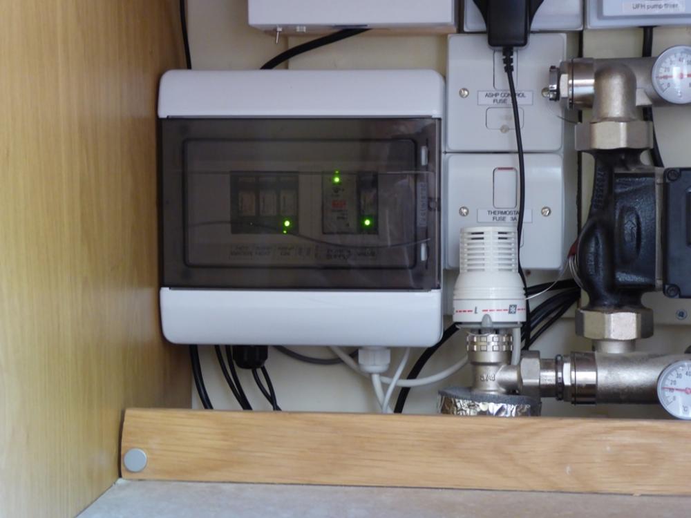
It's not that, the thermostatic mixer valve is almost always directly mounted on the manifold and UFH pump itself, or very close to it, either as shown in my photo or as in these photos of other UFH mixing valves, taken at random from the web: The mixing valves are all at the bottom or lower left of each photo, with a temperature control knob. There is almost always a thermometer in both the flow and return manifolds to, to allow the UFH to be set up properly to give the desired differential temperature between the UFH flow and UFH return (not the same as the ASHP floa and return, they are separate; not all the flow from the ASHP goes through the UFH all the time, when the thermostatic valve senses that the UFH flow is at the set temperature it throttles back the flow and so some of the ASHP flow goes through the bypass, buffer tank, other heating appliances in the circuit etc, at the ASP set flow temperature.
-
They do come in different shapes and sizes, but all do the same thing, they ensure that the UFH runs at the set temperature, irrespective of the heat source temperature. Yours may be a smaller three port blender valve, with a smaller control. I've not seen a UFH manifold without a form of temperature control valve, either a two port one like ours, or a three port one. The three port ones look very much like the ones used on thermal stores or other hot water storage systems to control the DHW temperature. The UFH flow temperature needs to be adjusted to give just enough heat to the floor to warm the house quickly enough, without too much overshoot, just for comfort. Having a high UFH flow temperature tends to result in greater swings between the maximum and minimum room temperature, as it takes time for the heat to get from the UFH pipes to the floor surface, so if the UFH pipes are running too hot, the heat will continue to soak out to the floor for a long time after the thermostat has turned the heating off, resulting in the rooms continuing to warm up for some time. We suffer from this if the flow temperature exceeds about 26 deg C; as long as I keep the thermostatic valve set down below that level things are fine. The ASHP flow temperature, just like any other heat source, needs to be set to give best performance at the load it is operating at. Running an ASHP at too cool a flow temp will tend to cause the unit to modulate down to a low level, all the time, and never operate at it's most efficient temperature. One key point is to get the difference between the flow and return temperature of the ASHP up to a reasonable level, as this sets the modulation level and also has a significant impact on the anti-short cycle timing. If the ASHP is running with the anti-short cycle system kicking in a lot, then it's efficiency will drop because of all the additional starts and stops, especially in milder weather, when the heating isn't being required to deliver much heat.
-
It's something you can probably do yourself. On the UFH manifold there will be a thermostatic mixer valve, either a two or three port one, that sets the UFH flow temperature. We have a simple two port one, you can see it here, the white control at the left of the lower manifold, in the centre of this photo, where the flow comes in from the ASHP: Then, when this is set to give the desired UFH temperature, the ASHP flow temperature can be adjusted upwards. I'd suggest setting it to around 40 deg C, as I found that seem to work very well for ours.
-
So why not just wind down the mixer on the UFH and wind up the setting on the ASHP to a tad over 35 deg C? Running the ASHP under 35 deg C isn't going to make it run more efficiently, if lightly loaded and set at such a lower flow temperature it will probably be running less efficiently, as the differential temperature between flow and return is likely to be pretty low.
-
I'm a bit puzzled. We run our UFH with a flow temp of around 25 to 26 deg C, but run the ASHP flow at a fixed 40 deg C, as that seems to give the best COP in practice. So, why couldn't the Panasonic Air Rad have been plumbed directly across the ASHP flow and return?
-
Spot on. I went through this process when designing our house, as I had to work around not having large openings on the North wall. My study gets around not needing an escape window just a narrow, high level, clerestory window to provide some North light, just because I arranged it so that the door opened on to the hall. My wife's study is accessed from the living room, so that has a French window leading to the patio. Upstairs you need escape windows, with no locks, from all habitable rooms, as the hall/staircase isn't considered a safe fire escape route from upper floors, unless it's fully enclosed and fire protected.
-
So, essentially they started the stables development to the point where the PP was locked in (looking at the Google Earth image from July this year), and have then done nothing more, other than continue to live in the caravan they put on the site as a "site hut"? Nice wheeze, as there's probably no time limit on how long they have to complete the construction of the stables, so they could pretty much stay there forever.
-
ESP are a known to be good supplier (with a couple of minor niggles about representation of stuff) and for something like this I'd say go for it, as I'm sure it will be OK. It may well be Chinese, as ESP seem to focus on direct import from China of products made for the Chinese domestic market, then getting them through UK approval, but frankly I suspect the same may well be true of stuff from a lot of other suppliers. I have a feeling that their business model is very like that of Navitron, in that they source Chinese made products, check them to make sure they are reasonable quality, then resell them here. That has to be better than taking pot luck with buying direct from China, in my experience. Not sure why UFH pipe needs to be WRAS approved, though, as generally WRAS approval is only required for potable water stuff. If it we me I'd buy it, as I've spoken to the ESP guys at length in the past and found them to be OK in the main. Try calling them direct - you might get the ebay fees waved.
-
We have a passive slab, and we're on gault clay. Essentially it's a way to get a very well insulated, thermal bridge free, foundation system with usually less excavation work and much less concrete used. The idea is an old one, and the basic principle is that if you spread the load imposed by the mass of the house over a wide area then the soil maximum bearing stress can be far lower than for conventional strip foundations, where all the load is taken on narrow strips. It's a bit like the difference in load that a flat soled shoe will impose on the ground versus a stiletto heel. Without getting in to too much detail. a passive slab relies on a layer of crushed stone to spread the load evenly into the ground, very much like railway ballast stone spreads the load from heavy trains. If the maximum allowable bearing stress of the soil is very low, then increasing the depth of crushed stone gets around this. For our hard clay we only needed 150mm of compacted stone, and the insulation was laid on that, with some grit blinding to smooth it, and a 100mm thick reinforced concrete slab was poured into the "tray" made by the insulation. As an aside, the underfloor heating pipes were also fitted into the slab, as it's very well insulated from the ground beneath and around the edges. The final benefit was that the slab was poured and power floated dead flat, to exactly the level needed for the final floor finishes, so there was no screeding etc. It took four days, start to finish, to lay our foundations and slab, with three guys. The bits of interest are here: http://www.mayfly.eu/2013/10/part-sixteen-fun-and-games-in-the-mud/ The week after that foundation was put in, the house went up: http://www.mayfly.eu/2013/10/part-seventeen-day-one-of-the-build/ and http://www.mayfly.eu/2013/10/part-eighteen-a-house-in-4-12-days/
-
The bottom line with a lot of this lender paranoia is that they are more focussed on having nice bits of paper than there are in whether the house is really sound. Valuation surveys are a bit of a joke (we've just had one on our old house) and consisted of a bloke walking around for ten minutes, making some notes on a form. The closest he got to actually inspecting anything was to poke his head through the loft hatch and shine a torch around. The daft thing is that he wouldn't use the loft ladder, or the light in the loft, but insisted that for H&S reasons he had to use his small telescoping ladder and a small maglite torch. I'd expected an examination of the roof, the new flat roof we laid last year, checks on loft insulation, state of the roof timbers etc, but it was clear that he was more interested in the folder of bits of paper than the house itself.
-
You want standard outdoor building mastic probably. It's not expensive, but to ensure the render people are happy with it, give them a call and ask what they normally use, as you don't want the mastic to have some unwanted reaction with the render.
-
The mastic has to stay slightly flexible to deal with expansion and contraction, and I doubt that expanding foam would. I also think that the render would find it's way into the holes in the trimmed foam, rather defeating the purpose.
-
A Robust Non-Gas Heating / Water System for Rentals
Jeremy Harris replied to Ferdinand's topic in Boffin's Corner
All electric is the obvious way to go in terms of reduction of ongoing maintenance and inspection cost, but will hit the EPC quite hard. One option may be to mimic what the big boys do to get around this problem, and fit small PV systems. A few panels can earn you a fair number of EPC points, and may well be cheaper than more expensive insulation work. It goes against the grain to suggest this, as clearly better insulation and airtightness would be a more responsible option, but you'r fighting costs here, and I suspect a small PV system may well be cheaper than something like EWI, and earn as many, or more, EPC points. This would be particularly true if installing systems on several houses, as the chances are that you would get a better deal. I'd just keep any revenue yourself, and let the tenants benefit from the slight reduction in electricity use, as the paperwork to do anything else would be too much hassle, I'm sure. -
Beam theory says it has virtually zero effect of stiffness or ultimate strength, and I beam joists are designed to meet maximum allowable centre deflection criteria, so are massively under stressed, anyway. Take a look at the main spar on an aeroplane - that's a simple beam that's massively loaded in comparison to anything in a house (the margin may be around 1.5 for an aircraft, versus around 5 for buildings, where there is a greater probability of unknown loadings being applied) where the web will often be full of whopping great holes. The problem with OSB web I beams is that the OSB used is not great, plus OSB relies on having lots of bonded wood chips over a large area to gain its shear strength. Anyone who has cut a bit up will know that small bits of OSBare really weak in shear compared to large sheets.
-
I've heard of several tales recently where sellers have had to rush around spending money to get proof that the house they are selling is compliant with the building regs that applied at the time it was built. It's one reason I ripped out all my workshop wiring at the old house a couple of weeks ago and refitted the single socket, light switch and pendant light that was in there when we bought the house. I've also carefully collected together all the paperwork on things like the new windows and doors we had fitted years ago, the new gas boiler and all it's annual service chits, the paperwork for the new flat roof we had fitted a couple of years ago, and the couple of wiring jobs where I have a chit, ready to sell the house. I've also heard that there's now a pretty good chance that a lender will want to see an up to date electrical installation cert, as the house wiring is over 25 years old, so I'm arranging to get one of those as well, just in case. I've already tested every circuit so with luck the official EIC will be quick and easy. The last thing I want is last minute hassle with the sale because a lender throws up objections!
-
Pretty much any radiator can be turned into an electric one just the same way as any towel rail can, as the fittings are all the same. Heating elements are available in a side range of lengths and power ratings, so if you like the look of a particular radiator style, then just fit a towel rail element and fill the thing with suitably mixed car antifreeze, the type with corrosion inhibitor. If you're a cheapskate, then make your own mixture - it's only ethylene glycol water and sodium nitrite (as the corrosion inhibitor), mixed roughly as 30% ethylene glycol, 0.5% sodium nitrite and the rest made up with water to 100%. I tend to buy bulk chemicals that are used in common stuff like this, as it's a heck of a lot cheaper. My home made windscreen de-icer spray (just isopropyl alcohol, mono ethylene glycol and a tiny amount of salt-free detergent, has been doing well over the past week, when both cars have been well frozen in the mornings. A 1 litre spray bottle of my home-brew de-icer is around 20% the cost of buying the stuff ready mixed.
-
In essence, you can make stiff beams lots of different ways, but all use the same core principle of having the primary load bearing elements as far away from the centre as possible in order to increase the second moment of area (or moment of inertia). The objective is to have as high a second moment of area as possible with the least amount of material. The shear web (which is really noggins in the Larsen truss design) only takes shear loads and keeps the structural member separated so as to maximise the second moment of area. It's very common to have large holes in sheet shear webs, to lighten the beam and reduce cost. The stress in the centre of the shear web is zero, which is why it can have big holes cut in it. The most common example of this we see is with Posijoists, where the shear web is just a load of shaped nail plates keeping the two structural members apart. There are some timber I beams around with punched out holes in the shear web, really just to make it easier to run services, but these could just as easily be used to reduce thermal bridging in a wall or roof structure. The problem is cost, I think. Basic I beams are really very cheaply made when you look at them, and the OSB shear web is the cheapest way of doing the job. OSB is OK for a lot of things, but if you cut lots of holes in it fairly close together it's shear strength isn't great. Ply webs would be ideal for this, but the cost would be a fair bit higher, I'm sure. The reason for twin stud walls using noggins and not ply spacers, as John Larsen originally used, is down to ease of manufacture. It's a great deal quicker to just position noggins and press on nail plates than it is to faff around nailing on ply webs.
-
There's only three noggins per storey, though, with a twin stud. and the timber is standard stud work timber, so 89 x 38, inside and out. The noggins are also 89 x 38, as are the top and bottom plates. The fill point is really more about speed, as every bay has an individual fill hole at the top with a twin stud wall, just as with an I beam. The difference is that the cellulose partially fills the adjacent bays through the big gaps, so once the first bay has been filled the rest along a run are a bit quicker. The high pressure ensures the fill is even, either way. FWIW, our roof is cellulose filled I beams, with an added bit of studding spaced 10mm off the bottom of each I beam to increase the depth to 400mm.
-
Trees with TPAs can be condemned if they are diseased or rotten. Scraping away some soil around the largest roots, drilling some small holes and filling them with old car battery acid has the curious effect of making a tree look pretty rotten after a few months...............


