Jeremy Harris
-
Posts
26430 -
Joined
-
Last visited
-
Days Won
360
Everything posted by Jeremy Harris
-
Mice can apparently live without water, as long as they have food that they can extract a bit of moisture from. They need to eat around 20% of their body weight every day, which seems a lot. For me that would mean eating around 17kg a day...
-

Ramblings on automatically reading meters
Jeremy Harris replied to TerryE's topic in Boffin's Corner
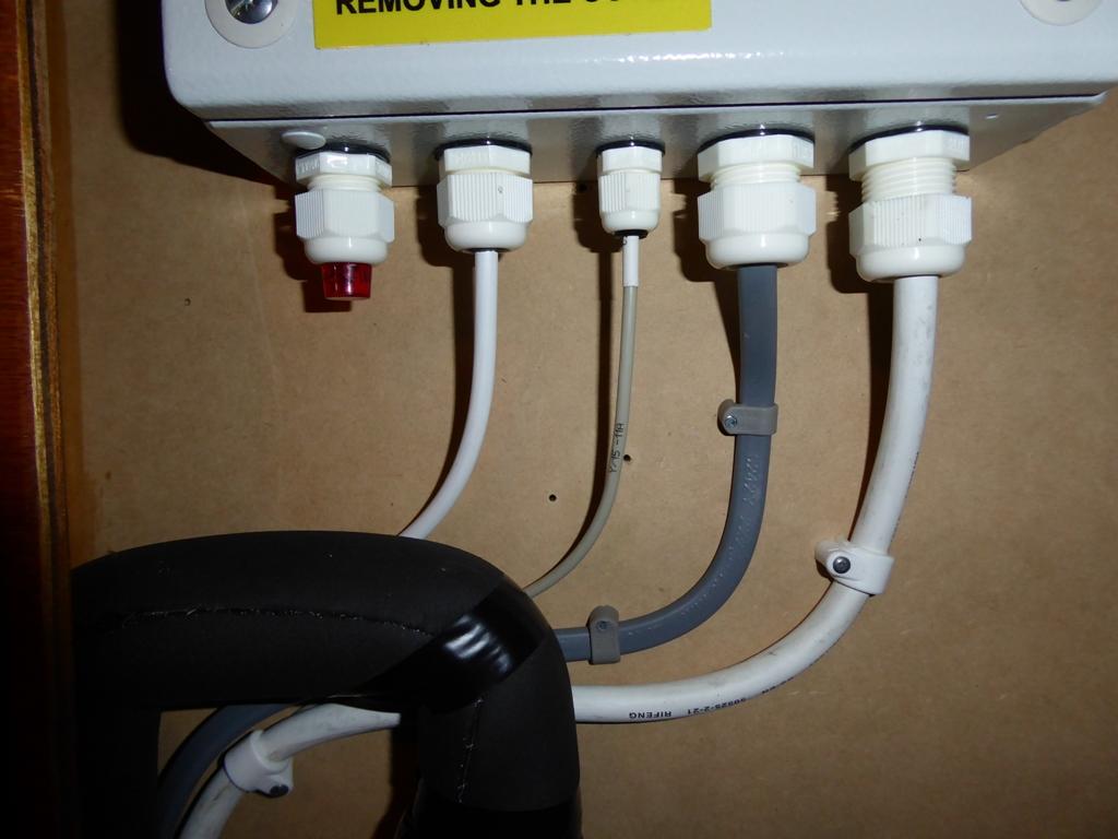
Dead easy on this one, as the case is just clipped together. Inside there is a small circuit board with the burden resistor and lugs and strain relief for the two core cable that's normally fitted. I removed the cable and burden resistor and fitted a three core screened cable and two burden resistors in order to get the balanced signal needed to feed the AD7755. These current transformers are readily available on eBay, just search for SCT-013 and loads will pop up, with different current ranges. -
Ramblings on automatically reading meters
Jeremy Harris replied to TerryE's topic in Boffin's Corner
No, it doesn't require anything other than clipping a current transformer core around the meter tail. I have the power cable for the unit hard wired to a 6 A DP RCBO, but it could just as easily be wired to a 13 A plug to power the unit and obtain a voltage reference. This is the clip-on current transformer I used, which is similar to those used by PV diverters: http://vctec.co.kr/web/product/yhdc/pdf/SCT013.pdf Here's a photo of the (blue) clip-on current transformer in the meter cabinet: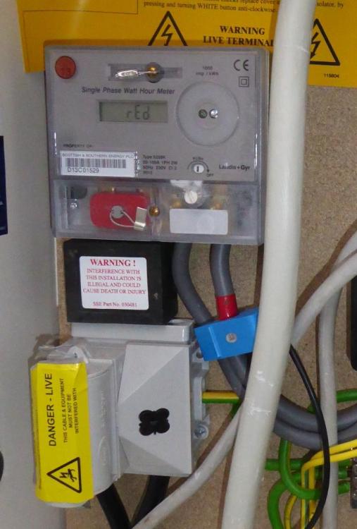
-
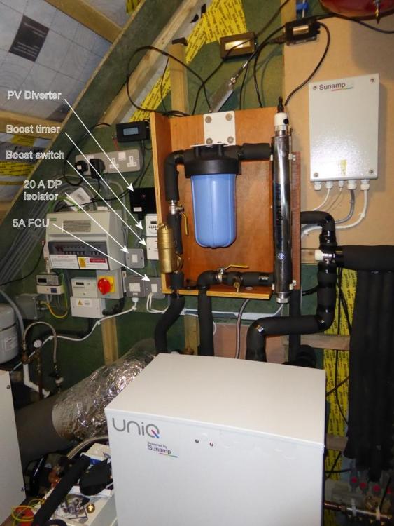
This photo isn't that clear and doesn't show that there are four wires coming from the PV diverter into the timer and boost enable switch, an always-on line direct from the 20 A isolator, a switched line from the PV diverter, and a neutral and PE. The switch in the time switch is connected in series with the boost enable switch below, so timed boost only works when the boost enable switch under the time switch is on. The timer has an over ride push button that allows a manual boost at any time. The RCBO protected 20 A supply from the consumer unit runs to the 20 A DP isolator, and from there one cable runs to the PV diverter and another runs to the 5 A fused connection unit. The two cables from the FCU run to the Sunamp control box and the flow switch that controls our preheat pump. The PV diverter only switches the line conductor on and off, using a 25 A solid state relay. It's fine to just bypass this solid state relay with the time switch contacts.
-
I can't understand why a PV diverter needs to know the temperature of anything. Mine only knows about the power flowing into or out of the house supply and needs nothing more to work perfectly. Others are similar to the way mine works, as I looked at how a few work before building mine, although I haven't heard of the Apollo GEM before now. The main variation between the different makes available is how they switch excess power to a load (and it can be any load, doesn't have to be a water heater). Mine uses an energy bucket principle, with bursts of power being zero-crossing switched to the diversion load, others use a variable power switching method, either by using phase control or by using a zero-crossing pulsed control. None should need anything other than instantaneous power sensing at the meter tails to work properly. I just boost mine by switching out the PV diverter and applying power directly from the supply to the Sunamp. I have a time switch to do this, in series with a 20 A switch to isolate the boost function in summer. Dead easy to wire up and allows the time switch to provide an early morning two hour boost in winter when there's not much PV generation, or a manual boost by pushing the over ride button. The neon I used came with nice long leads that will easily reach the relay A1 and A2 connections, £1.90 from eBay, including postage. It's 10mm in diameter so is a nice snug fit in the spare cable gland: https://www.ebay.co.uk/itm/Red-Neon-Indicator-Pilot-Signal-Lamp-AC-220V-w-Cable-UK-Seller/372357642057?hash=item56b23eb749:g:vTAAAOSw7mpbPRpC:rk:1:pf:1
-
Shouldn't be a problem at all for a properly designed PV diverter. Any PV diverter that senses true power at the meter tails will work fine, as all that happens is that it will sense the relay opening as a reduction in metered demand, which will then cause it to try to divert more power by leaving its SSR on. As soon as the Sunamp power relay closes then the diverter should automatically sense the increased demand and start adjusting the on/off cycling of its SSR in order to ensure the maximum level of self-consumption. My PV diverter isn't in any way unique in the way it operates, and it had absolutely no problem in dealing with the start up pulsing from the Sunamp controller. Having said that, as the start up mode only lasts for ten to fifteen minutes, it makes sense to just switch the PV diverter to bypass mode and apply full power to the Sunamp input. That will ensure that the start up warming process happens as quickly as possible. From then on it's unlikely that the Sunamp heat cell will cool down to the point where it needs to do a cold start, as this only happens when all the heat has been taken from the cell and the PCM is completely solid.
-
I'll lay money on them being able to get in and out, too. I can't see a mouse living in a dry sealed space for more than a day or two. Time to go looking for ways in which they are getting in and out, which may well be very challenging indeed, given how small a hole they can get through.
-
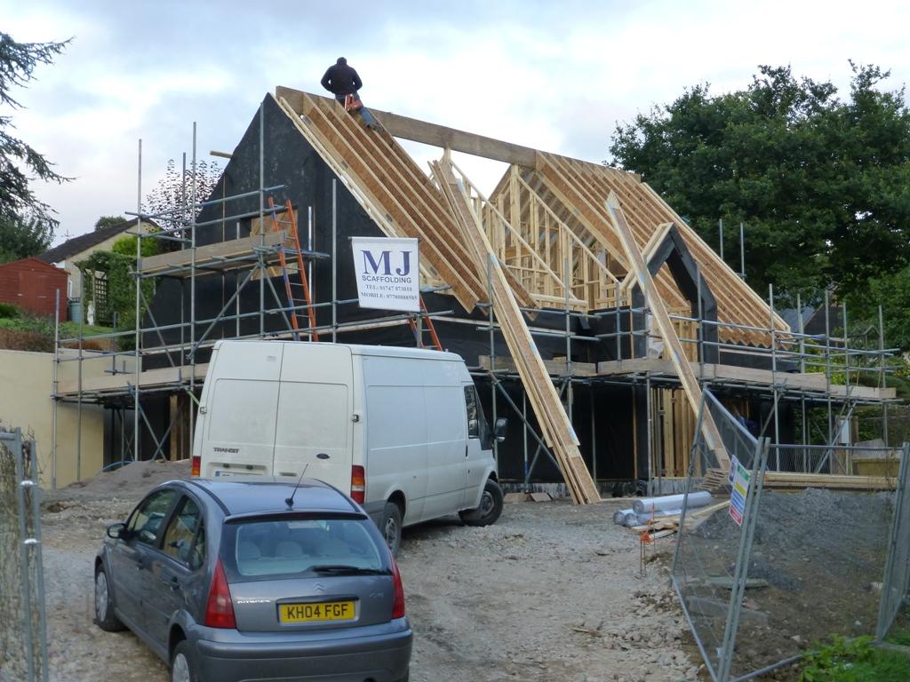
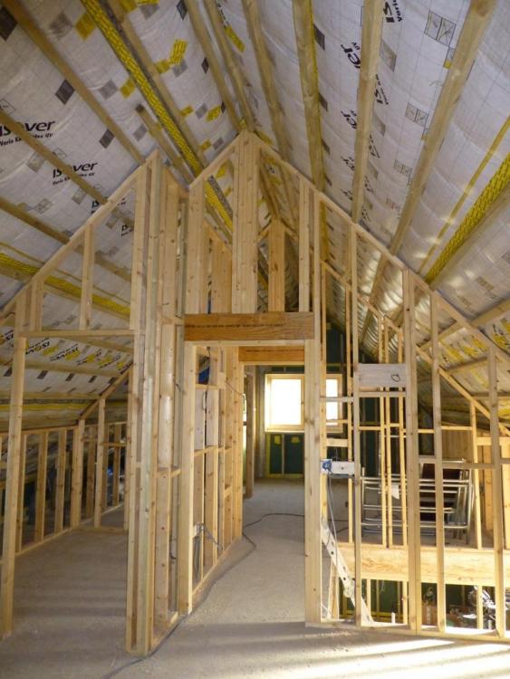
We have Posijoists and a big ridge beam supporting deep I beam rafters for our room-in-roof design. Works well, but does need a deep ridge beam to take the load of the rafters hanging from it. With this design there are no tensile loads transmitted to the first floor joists, as the rafters hang from the ridge beam. Some photos:

-
It's not a problem, as the relay in the Sunamp control box works much like the thermostat in an immersion heater, so when the relay opens the PV diverter can't divert power, senses this, and so switches the power on continuously (as there is no load). When the Sunamp main relay connects again, maybe 15 to 30 seconds later, the heating element starts drawing power and the PV diverter may then start switching power on and off again, depending on the excess being generated. This warm-up cycle only happens when the Sunamp heat cell is completely exhausted and cold, so really only once during commissioning, and again if the power has been off for a long time. Most of the time the PCM will stay liquid around the heating element and the cold start pulsing won't come on. The duration of the cold start pulse period seems to be around 5 to ten minutes or so. As soon as the lower temperature sensor in the heat cell reaches a warm enough level the cold start mode is disabled and the power relay stays on all the time. One slight snag with the Sunamp Uniq models that have an electric heating element is that you can't tell whether or not the power relay is on. I fixed this on mine by adding a 230 VAC neon indicator to the power relay A1 and A2 terminals, with the indicator fitted into one of the spare cable glands on the box. I can now see at a glance whether the Sunamp is calling for heat or not, which is very useful, IMHO.

-
Ramblings on automatically reading meters
Jeremy Harris replied to TerryE's topic in Boffin's Corner
Yes, you can. The only thing to watch is the effect of small changes in current demand by the electronics, which changes the sampled voltage. I got around this by using a transformer with two separate secondary windings for the power supply, as the voltage drop is almost entirely due to the winding resistance. This is the circuit diagram for my unit; the PIC outputs serial data to the wireless link. The local display port connects to a small LCD with another PIC that translates the frequency and direction signals into import/export power: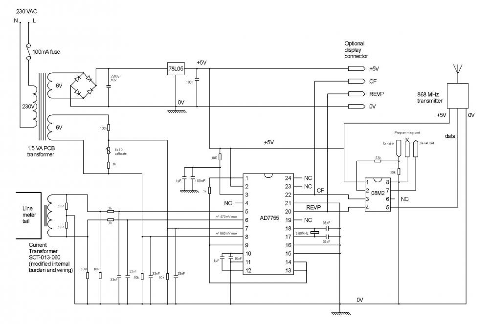
-
Ramblings on automatically reading meters
Jeremy Harris replied to TerryE's topic in Boffin's Corner
You might also want to look at energy metering chips, as used in electricity meters. They are dirt cheap (around 50p or so) and have pretty accurate 16 bit A/Ds for measuring voltage and current at a fast sample rate (much, much faster than something like the Open Energy Monitor, that uses the Arduino A/Ds). I'm using an Analog Devices AD7755 (now obsolete, but there are loads of others around) which measures current and voltage right at the meter and sends instantaneous power data back to the house via an 868 MHz data link. Anything can then use that data. I have a display unit built in to a plug top that shows import/export plus the power, the house data logging system records the data and also the PV diverter unit uses the data to turn the Sunamp heating element on and off, via a 20 A SSR. It would be dead easy to add one of these metering chips to something like an ESP8266, as the output is a pulse train with the frequency proportional to power plus a pin that indicates direction. No need to break into the meter tails, either; I use a 100 A current transformer for the current signal and a small mains transformer to give the voltage signal. This old datasheet for the AD7755 might be of interest: AD7755.pdf -
ESP are another importer of Chinese made heat pumps, which isn't an issue if the price is right and anyone buying one accepts that there is a high probability of long term support being unreliable at best, and in all probability unavailable. Having said that, the people at ESP are honest and reasonably open, with the sole exception that they have been shown t be a bit deceptive about the products they have sold in the past. My specific gripe is that they advertised an active MVHR for a time and the manual they provided for it was actually a copied version of the Genvex Premium MVHR manual, even down to exact copies of the product illustrations, despite the fact that the product they were selling was a Chinese copy of the Genvex. My view remains that what they were doing was "passing off", in consumer law terms, albeit, perhaps, unintentionally. To give them credit, they no longer sell this product, I believe.
-
The Kingspan branded Carrier is a pretty good ASHP, so it's very well worth trying the get it going if you can. Carrier are the worlds biggest manufacturer of heat pumps, with over 100 years experience, so even if you need to spend a fair bit in order to get yours running I think it will be worth it.
-
Our house also has a big laminated timber ridge beam (~450mm deep) that runs the length of the house, supported by both end gable walls and two internal walls, 2m apart, 1m either side of the longitudinal centreline. We have 403mm deep rafters, hung from the ridge beam down to the top of the walls. The rafter pitch is 45 deg, which gives us an external appearance that's close to that of a bungalow (which is all the planners were inclined to approve), yet gives us around 4m of height in the vaulted ceiling first floor rooms, plus is gives us a 6.5m high vaulted ceiling in the entrance hall, that definitely makes a relatively small house seem a lot larger and more airy inside. There are some photos on our blog, along with the whole build tale: http://www.mayfly.eu/
-
Air blower treatment plants - power consumption.
Jeremy Harris replied to ProDave's topic in Waste & Sewerage
My guess is that they have changed the pump from the Secoh EL-100C to the Secoh JDK-S-100, which has the same air delivery rate and pressure but uses 30% less power. -
Acceptable tolerances and out of spec windows
Jeremy Harris replied to Besidethewye's topic in Windows & Glazing
Getting the levels right in a slab for Part M compliant thresholds was a pain, I found. Getting accurate dimensions from the door frame suppliers was the main issue. In the end things worked out OK for us purely by luck, as I opted to get the slab level at the door threshold locations the same as the slab level internally, as I just couldn't get any reliable information from the door and window suppliers. My plan was to grind down the slab in the door area if the doors ended up being supplied with thresholds that were over 30mm deep, but in the end I didn't need to, thank goodness. We were fitting 12mm thick travertine up against two of the door thresholds and 12mm thick bamboo flooring against the French windows, both bonded down with ~3mm of adhesive and it turned out that the doors were all supplied with ~28mm deep thresholds, so we've ended up just being compliant with Part M, with a threshold height of ~13mm to 14mm on all the external doors. I can understand why this detail causes a bit of pain and grief, though, if my experience of trying to get accurate dimensions from a supplier was anything to go by. -
ASHP, SUNAMP, UFH, PV Panels
Jeremy Harris replied to Coops85's topic in Air Source Heat Pumps (ASHP)
The simple answer is that it can't be enforced at all, and should never have been a condition in the first place, given that CfSH was abolished years ago. Our planning officer removed the condition on our draft approval that said we had to get enough points to meet CfSH level 5 just before it was signed and sent to us in 2013, so there's no way that a planning consent that's still valid now, over five years later, can have a valid CfSH level requirement, as there's no underpinning legislation to back any local planning policy any more. -
ASHP, SUNAMP, UFH, PV Panels
Jeremy Harris replied to Coops85's topic in Air Source Heat Pumps (ASHP)
When we submitted our planning application in December 2012, the Code for Sustainable Homes was still in force and we were required, by local planning policy, to build to level 5. By the time our planning application came up for approval, Code for Sustainable Homes had been abolished, so I rang the planning officer and he told me that we no longer needed to build the bicycle store, following that up with an email to confirm. So, any condition that came about as a consequence of needing points to reach any CfSH level became void by early 2013. There have been no changes to re-introduce anything like CfSH since then, either. Your planning consent must be after CfSH was abolished, as consent only lasts 3 years, and on renewal after that time any unenforceable conditions should have been removed, as the underpinning policy would no longer be valid. Although it's clearly very worthwhile to reduce energy consumption as far as practical, and fit renewables if possible, there isn't any way that a local authority can continue to enforce a planning condition that was reliant on legislation that has long since been rescinded, so I would be very inclined to ask for the condition to be lifted, as that then gives you the freedom to choose to do what best suits you. -
ASHP, SUNAMP, UFH, PV Panels
Jeremy Harris replied to Coops85's topic in Air Source Heat Pumps (ASHP)
I agree with @ProDave, what electricity supply you have is not a valid planning consideration, so the local authority cannot have any say in it and it is not a valid planning condition - ask that it be removed on the basis that it's not supported by any planning policy. The DNO determine how much export current per phase they will allow for microgeneration, although they have an obligation to accept 16 A per phase, under G83, without the customer having to obtain consent. We have 6.25 kWp on a single phase, and I was told by the DNO that we could have up to 10 kW if we wished, as there are only three properties fed from the run of 95mm² Wavecon cable that runs from the nearest distribution transformer. I did need to get written consent from the DNO for the 6.25 kWp installation, under G59, but it was a formality and came through very quickly (less than a week). -
Air blower treatment plants - power consumption.
Jeremy Harris replied to ProDave's topic in Waste & Sewerage
@Ed Davies, your thinking mirrors mine. Although we're not off grid, we have enough PV generation capacity to more than cover our annual electricity use, and it helps a fair bit if I can reduce our power consumption during the hours of darkness. Even in mid-winter the PV will generate enough to power the house normal background load, and I've been gradually looking at ways to reduce this during the night. I run the house network stuff (VDSL2 modem, router, switch, file server etc) from DC via PoE, with the DC coming from switched mode DC-DC converters running from a battery bank. The charger for that battery bank is currently just on a dumb timer, that charges it up during the day, allowing the batteries to power everything in the evening and overnight. The next step will be to add some intelligence to the charging system, so it only charges when there is excess solar (pretty easy to do as I have an 868 MHz RF data link from the meter cabinet that transmits instantaneous true power and direction data every 10 seconds). The borehole system doesn't draw power overnight, as it takes around 300 litres to be drawn off before the pump comes on, and water consumption in the evening and at night is fairly low. My car charge point only normally triggers a charge when a high export power is detected, not perfect, but a reasonable compromise given the inherent limitations of the J1772 protocol. Reducing the treatment plant background demand makes a worthwhile difference, especially if I can add some intelligence to it later, so that the duty cycle varies in proportion to the amount of use the unit gets. I may well be able to do this by using the discharge pump on time as a trigger, as that operates from a float switch. Night time operation of the discharge pump seems unlikely, and so just detecting when it's operated, waiting a set period of time with no operation and then reducing the aeration pump on time, may be a good way to reduce overnight power consumption. @dpmiller, thanks for another data point on acceptable on/off cycle times. -
Air blower treatment plants - power consumption.
Jeremy Harris replied to ProDave's topic in Waste & Sewerage
Thanks, that's a useful data point to add to the various different on/off times that I've heard of, and as it happens we also have a Biopure 1, and the same Secoh pump. I'll change the duty cycle on the timer next time I have the lid open and a laptop handy to programme it and see how it goes. Our unit will only be lightly loaded with the two of us, and I'm pretty sure that it's still over-aerating at the moment. -
Air blower treatment plants - power consumption.
Jeremy Harris replied to ProDave's topic in Waste & Sewerage
From what I've been able to find out, leaving the pump off for more than a few hours may well cause sludge to settle over the air outlet holes and cause blockages or increased back pressure. The timer systems seem to pulse the pump on and off, with on times being long enough to cause any sludge to get recirculated back into suspension (so around 15 minutes to half an hour minimum I think) as well as cause enough oxygen from the pumped air to dissolve into the effluent. It seems to be an imprecise art, getting the pump on/off times right, and I've arranged for the duty cycle on the timer I've built to be programmable, so that I can change it around to see what the effect is. Right now it's operating for 20 minutes off, 40 minutes on, but that's a pretty conservative setting, I think, as I've heard of much longer off periods with some other timed units. Changing the pump flow rate isn't easy, as they all run synced to a half wave rectified mains supply. Adding a valve to throttle the airflow stresses the pump diaphragm, much the same as high back pressure from sludge build up. @PeterStarck found that high back pressure from excessive sludge build up caused a pump diaphragm to fail, IIRC. Almost all aerated units seem to massively over-aerate, because they all use pumps that were originally designed to aerate Koi carp ponds. Over aeration errs on the side of caution, as it does no harm and ensures the output always has a pretty low BOD. The main disadvantage of over-aeration is the higher than strictly necessary power consumption. There are higher efficiency pumps available that reduce power consumption a bit. Our unit is running on a Secoh JDK series pump, which has a lower power consumption for the same air delivery rate as the older Secoh EL series pumps. -
As above, there shouldn't be smells from the unit, as that suggests that the foul drain isn't well vented. The pumps aren't usually variable speed, but the way they are mounted can make a big difference to the noise level. At first I just lifted the pump out and put a layer of dense neoprene foam underneath it and that reduced the noise level a fair bit. I went on to glue some acoustic foam inside the GRP housing and that quietened it down even more. My reason for moving the pump up to the new stone and concrete box was as much to do with making access to the pump for annual maintenance easier as anything else. The fact that it almost completely reduced the humming noise from the unit was a useful additional benefit.
-
Airtightness and first fix
Jeremy Harris replied to dnoble's topic in Environmental Materials & Construction Methods
It's debatable as to whether it's worth the trouble of pulling things out and putting sealant in, TBH. In our case all the nail heads where the boards were fixed to the frame were covered with airtightness tape, but our lining is 12mm Spano Durelis, rather than Smart Ply. At a guess I'd say that Smart Ply may well be more tolerant of nails going though it. -
Inverter control allows the heat pump compressor and fan to run at a speed that's proportional to the heating/cooling demand, very like the way a modulating boiler works. This means that it has a very much lower starting current, so no starting power surge, and much reduced defrost cycling, as the heat pump will rarely run at a high enough power output to ice up the evaporator. Generally, inverter controlled units are a fair bit more economical and are always a lot quieter, as they will spend much of their running time at a lower than maximum power output. Non-inverter controlled units are "all or nothing", so when on they run at maximum power, and cycle on and off in order to control output. The give away that this model is not inverter controlled (apart from it not being advertised as such) is that it has a direct online starter and associated starting capacitor to the left hand side of the electronics compartment.