LA3222
-
Posts
1185 -
Joined
-
Last visited
-
Days Won
11
Everything posted by LA3222
-
Cable is 5 core SWA so £650 (excl vat) from what I can see. Hager TP&N DB - three phase & neutral Sorry, should have said that my supply is three phase?♂️ Yeah, the containment has me a little puzzled. AIUI the regs now state that the distribution board has to be metal? So what is the containment?
-
Just after a sanity check on what sort of price I should be looking at. Quoted £1500 for following (£1000 parts £500 labour): 12 way TPN distribution board with main switch kit 55m of 25mm SWA and a 63A supply from main board (kiosk has the service head/main board in it) Containment unit around board - not sure what this consists of? 3 metal clad sockets on a 20A radial circuit From what I can see the parts quote is there or thereabouts OK, not sure about the labour cost. I reckon 1 day to do all this? He said needs other bod to pull cable through, thats still £250 each if one day which seems high? TIA
-
I'm using Ejot TKE to fix 70mm insulation to the internal face of my SIP (15mm OSB). Kingspan Tek technical sent me to Ejot who said the fixing needs to penetrate 20mm beyond the OSB. I wouldn't recommend the TKE as the heads are a type of philips and an impact driver destroys them. If I was you I'd get some 80mm Spax SS screws with a torx head. Job done. I'm using Ejot washers too ...you will need washers of some description, I'm using SBH T 65 25.
-
Movement Joints between brickwork and blockwork
LA3222 replied to MortarThePoint's topic in Brick & Block
I dont seem to have any pics of my render being done. The renderers use some sort of grip (whichever brand is their preferred weapon of choice) to 'glue' all the beads in place during the prep stage. This includes the expansion bead. Once that is done and everything is covered a base coat went on, followed by mesh and then painting with primer coat and then the silicone coat went on. Took 5 blokes a week to do my house, 280m2. They used Johnstones Storm Shield, the manufacturer have warrantied their work - if the shit was to hit the fan i have no idea if that will prove to be worth anything?♂️ Most people on here will say K Rend, that particular brand seems to have become synonymous with rendering. Much like a hoover is called a hoover when there are many other makes out there than just 'hoover'. My renderer said Johnstones is better than KRend but then I'd be surprised if he told me KRend is better whilst working with Johnstones product. I'm sure @nod will say KRend is the mutts nut. I think you likely end up using the product ypur contractor likes to work with. -
Movement Joints between brickwork and blockwork
LA3222 replied to MortarThePoint's topic in Brick & Block
Nope. That is a plastic render expansion joint placed over the blockwork expansion joint and then rendered over. Gives a nice clean finish for the render. -
Movement Joints between brickwork and blockwork
LA3222 replied to MortarThePoint's topic in Brick & Block
Yarp...pretty simples. You need a load of wall ties in as well either side of the expansion joint. I filled the joint on mine with a load of white silicone, render bead went over that and then all covered with render. -
Don't think a lecture will be forthcoming on 'thermal mass', a lot of the protagonists who would 'bite' on this topic seem to have disappeared from the forum. Where is @Jeremy Harris nowadays?
-
@andy did you ever get around to producing an updated version of your schematic from what you originally posted here? If you did I would be interested in seeing it if at all possible? Ta
-
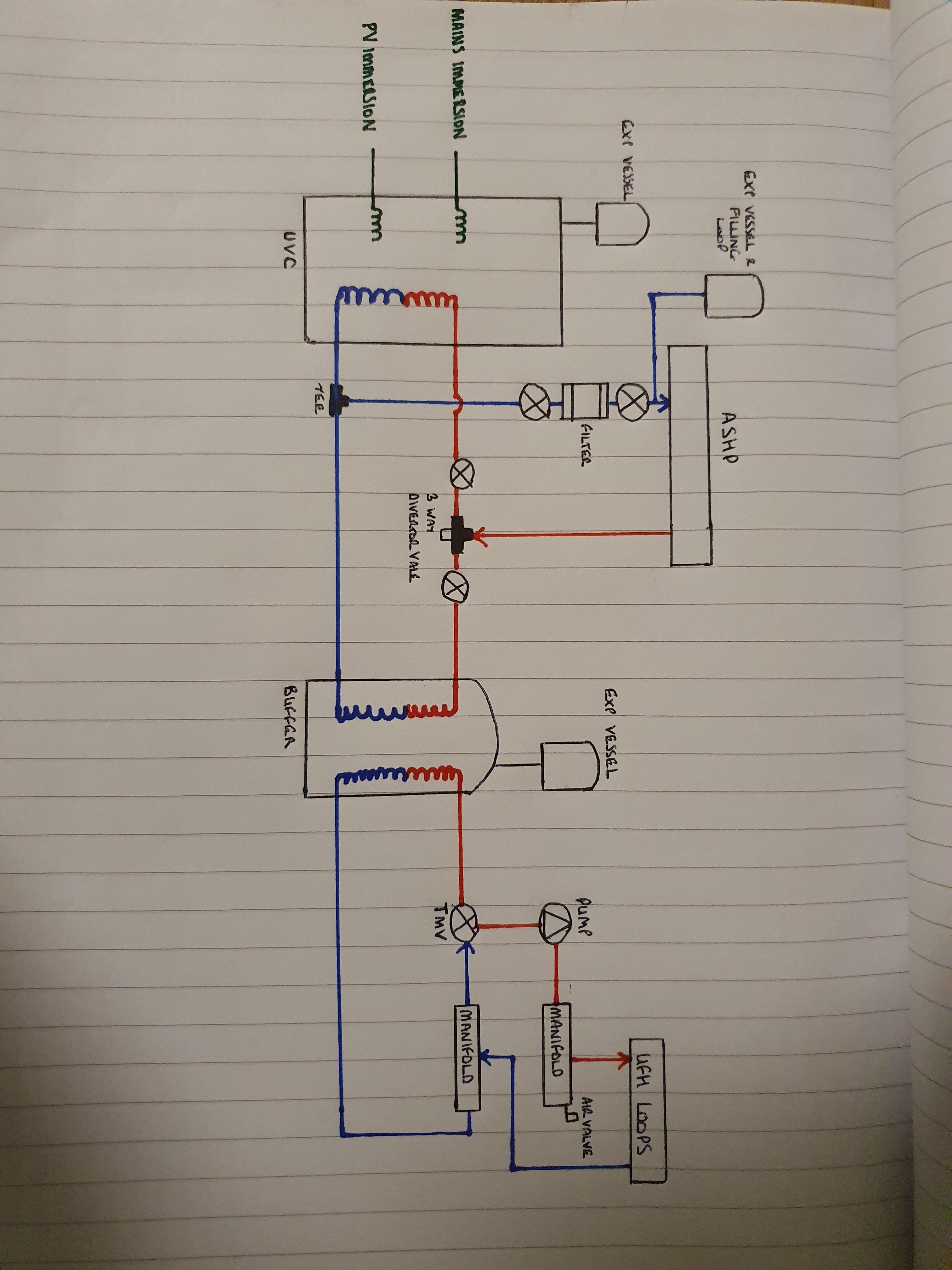
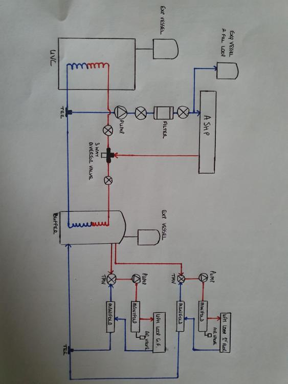
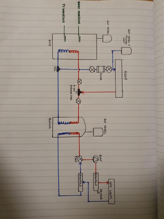
Thanks for the feedback Peter. So a bit of reading tells me that inhibitor goes into the UFH loops to stop bacteria etc. growing and potentially blocking pipes. The loop which goes from ASHP --> UVC/Buffer is filled as you mentioned elsewhere: Now I want to try and understand things a bit better if you don't mind giving me a steer?: Expansion Vessels on the UVC & Buffer - is this a standard detail due to those systems being a closed loop and pressurised? i.e the UFH loop which draws from the heated water in the buffer needs somewhere to expand into as it heats, the UVC is a 'closed' loop until a tap opens up to draw water from the tank. The circles with an X through them - these are something I've merged into my drawing from elsewhere, what are these and their purpose? Valves of some description, to isolate parts of the system? Are there any other components that should be included which i have failed to include which i should take into consideration? Thank you
-
I will be, just trying to work through it in baby steps so I understand what goes where/why and to make sure I don't miss anything.
-
Thanks Peter, F&E - fill & expansion? So make the expansion tank on the Buffer a fill loop aswell? Good shout on the immersions in the buffer.
-
Manifold system versus hot return system
LA3222 replied to Russell griffiths's topic in General Plumbing
I agree with you bud, a hot return is something I dismissed pretty early on. I wasn't able to centralise my plant room so its stuck at one end of the house with hot taps all over the shop, so my hot runs vary between 10-20m. I looked at how much volume is held in the pipe over those runs and assessed how long it would take hot to flow versus what the tap served and came to the conclusion that although instant hot is a nice to have, its not going to have any detrimental affect on our life not to have it. So good idea, but far from critical. -
Thanks for the steer. When drawing version 1 I forgot about the fact I have two manifolds tapped onto the buffer vessel rather than a coil (as per previous discussion on multiple manifolds!). Version 2 now attached, any feedback is much appreciated.
-
Hi folks, I've read everything I can on here and have tried to blend all the drawings I came across into one. The sketch below is where I am at so far, if advice can be given as to whether I'm on the right track, if not why then that would be much appreciated. TIA
-
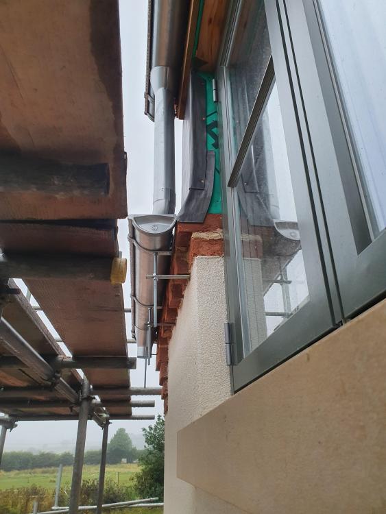
Nah, once the system as a whole is installed it will be fine. This is one of those things where all the parts work together to keep it dry. When I installed my velux I installed the felt correctly but it still leaked until I fit the flashing kit.
-
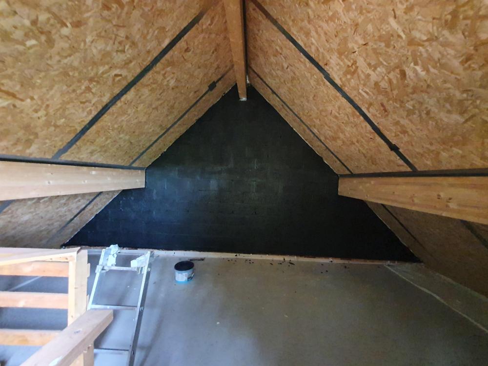
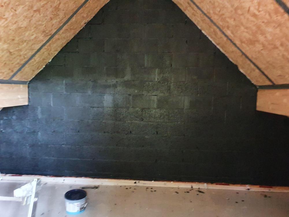
Just sticking some pics up of what it looks like in case anyone in the future is interested. Its really easy to use, just paint it on. It goes on navy blue and then dries black so you can easily see where you have been. I have put two coats on, could probably get away with one if you wanted to use it sparingly. Its texture is slightly rubber like, probably the best way I can describe it. As a parge coat it is a lot more expensive than using a cement parge but then I'd argue its a far superior method so on balance it comes down to a personal choice of what you are willing to spend in order to tackle the issue. I only had a couple of small areas to do so was happy to part with the money for it.
-
- 1
-

-
Grey/Green here - they tend to look one or the other depending on time of day/angle etc. White inside as we plan on using oak internally and the wood look of the windows wouldnt match.


-
DIY Solar Panel Installation
LA3222 replied to Triassic's topic in Regulations, Training & Qualifications
G83 application I believe? -
Ah right, @PeterW so if a coil is in it at all then its called 'indirect' and no coils at all is 'direct'. I was thinking that the direct refers to the UFH side having no coil but it is both sides. So if I understand it right now, a buffer tank with a coil in for the ASHP but no coil for the UFH side is still an Indirect buffer? I dont have anything specific in mind yet @Nickfromwales, I'm trying to understand the 'how' of things at the minute. So, i don't want the ASHP antifreeze running through the entire UFH system which means an Indirect buffer is the weapon of choice and Nick mentions not wanting to draw two supplies through one coil, so each manifold will need a tapping direct onto the buffer to circulate that water through the UFH system? TLDR: More than one manifold, use an Indirect buffer and have each manifold flow tapping on the buffer tank, tee the returns together then onto the buffer tank. I hope I've got this tight now?
-
Right, after a little bit of reading I have a few questions that I'm hoping someone can clear up for me if they would be so kind @PeterW or @Nickfromwales? Peter, you mention indirect/direct buffer and that has got me to thinking which you would use and why. What I think I understand: Both direct and indirect have a coil in them which the ASHP fluid travels through in order to dump heat into the buffer. Direct has a coil in, which is what the fluid within the UFH system travels through in order to extract heat out from the buffer. Indirect has no coil, so the fluid within the buffer is what travels through the UFH system. So, regarding putting heat into the buffer it makes no odds - it is the same for both. Taking heat out: Indirect - separate coils, bad for space in the buffer? A single shared coil, so the flow and return would need to be tee'd together? Direct - separate feeds to each manifold with the returns tee'd in? Each manifold draws heat seperately as required direct from the buffer. Question: which is the best way to skin the cat so to speak in terms of feeding two manifolds from a single buffer and why? My best guess - direct would be better as each manifold can draw separately from the buffer? Wheras indirect they would be sharing a coil? Thanks for any advice you can give.
-
Comparing heavy duty breathable underlay.
LA3222 replied to epsilonGreedy's topic in Roofing, Tiling & Slating
@epsilonGreedy I used Roofshield, everyone I've spoken to say its the best you can get. Not saying it is or it isn't, just what I was advised so I rolled with it. -
You won't be able to change the online version - at least I havent been able to. I downloaded a desktop excel version, split everything into individual tabs I.e. prelims, foundations, SIP, brickwork, roof......etc then work through each tab in isolation. Link them all to an overarching running cost on the first page which has all the tabs linked so if you amend a cost on a tab somewhere then the running total updates. I split each tab so it also has a 'spent' column next to the projected cost column, that way you can track where overspend have occurred.
-
That would be useful. I started off thinking about SunAmps when I started but have since decided to walk the well trodden route of UVC/ASHP/UFH. There seem to be a lot of threads on this topic but no 'definitive' schematic. I would have thought there would be a simple ASHP --> UVC & UFH layout out there with all component parts listed but that does not seem to be the case. Surely the setup should be fairly standard regardless of house type, size etc
-
I used estimators online too - its a good baseline to start from but I have made a lot of changes to my quote to get it to where I think it needs to be. I would recommend downloading the Excel version and then adding/changing etc. anything that requires it. Hopefully you should then reach a point where you have a good cost capture for your build, giving you a target to work to.
-
Thanks for the response Peter, I will have to digest/think about this later and hopefully it will make sense - plumbing seems to be an area that is pickling my brain! I have no issue with everything to the 'right' of the manifolds etc, its the stuff to the left where hot/cold water is supplied to the manifolds that pickle my head! I'm running with an ASHP to three way diverter supplying a buffer and UVC - its a work in progress. Trying to work through all the threads on this subject in order to cobble them all together as a design, I get the gist of it - once I've put pen to paper to draw something I will post it up in order to check I haven't made any fundamental mistakes!