jayc89
-
Posts
1389 -
Joined
-
Last visited
-
Days Won
1
Everything posted by jayc89
-
My assumption was based on this - https://www.heatgeek.com/condensing-boilers-efficiency/ Suggesting a "wide" DT is required, and a DT10 would be more inefficient than a DT of 20?
-
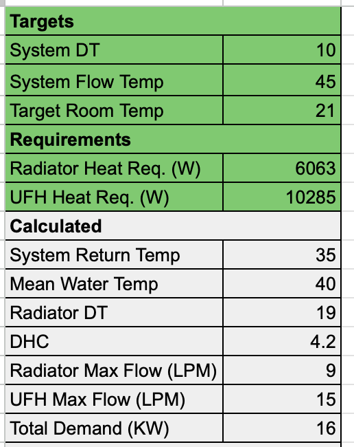
Is there a DT that's too low for a gas boiler? If I understand correctly, to get full efficiency from a condensing boiler, you want the flow above the dew point, but the return as cold as possible, so quite a wide DT. I.e. flow 55 and DT 20, for a return of 35? But I've also heard suggestions of some manufacturers now moving towards DT15 which contradicts this. Ideally, I'd have the system set up to run the same flow rate for both my rads and UFH, removing the UFH mixer (perhaps a pipe stat and zone valve as a fail safe to protect my tiles), and letting weather comp do it's thing, but to achieve this, assuming my calcs are correct, I'd need a boiler flow of 45 and a DT of 10, with a radiator DT of 19 (which makes them pretty big!) Whilst it simplifies the system, allowing me to remove mixing valves etc, am I sacrificing efficiency?
-
That's pretty much how I've ended up where I am. Before we knew better we got a local plumber to fit a new system; boiler, UVC, rads. All spec'd to, what I think was, a 70c flow temp. Even at that, all bedroom rads were undersized and have been replaced as part of going down to DT25. Whilst he was commissioning the boiler/tank we found the ground floor joists were rotten so had to deal with that and decided on a slab + UFH as a replacement. He didn't want to know anything about the UFH and just offered to leave a terminated flow/return pipe for someone else to connect into. This is why I've always been concerned the system hasn't been running as well as it could be. There are a lot of old school trades out there that don't necessarily do a bad job (although I'm far from pleased in my case), but they certainly don't work to more modern practices.
-
That looks very similar to the conclusions I've started to draw here. I assume the "Kimbo Pipe", is the oversized CCT at the boiler arrangement already discussed in here? A large piece of that design seems to be able to have different flow rates for DWH, Rads AND UFH, whereas, AFAIK, my boiler is only capable of two different flow rates; max when DWH is calling for heat and a weather curve otherwise. The video also suggests that the electronic blending valve on the UFH flow is also on a weather curve, controlled by the boiler. It was hard enough to find a weather comp unit for my boiler (Baxi discontinued it a couple of years ago), I highly doubt it will natively support a proprietary blending valve too. Looking at the ESBE actuators, it looks like you can fit a separate, external, weather comp sensor to it, but I then worry two weather comp units run the risk of working against each other, different curves etc. In the video it's also suggested to do away with 2 port zone valves, but surely something's still required on the rad circuit to avoid it receiving heat when only the UFH is calling for heat, no? That looks much better than my rudimentary calcs, thanks for sharing. Interesting that the max flow rate of the system wouldn't be much more than the boiler pump should be able to supply. I assume it'd still be best to keep the separate UFH pump as to not have the boiler pump running at max when both rads and UFH are calling for heat.
-
A couple of options are banded about on that video; 1) his original, which Andrew responded to 2) an updated version of it in response to Andrew's comments 3) Andrew's proposed design, which he tries to debunk 4) an alternative using an electronic blending valve instead If I understand them correctly, option 2 (his updated version), proposes to fit a pair of tees across the flow/return to the UFH, after the UFH pump/zone vale, with a gate/lockshield valve in-between the tees to balance at this point to the same DT as the rest of the system (so DT25 in my case). I don't think this is strictly a CCT set up, as the tees are actually bridging the flow/return pipes, not both on the flow, is that correct? Similarly, the "alternative" proposal is to fit an electronic blending valve ahead of the UFH pump, and again, bridge the flow/return to the UFH with a couple of tees and balancing valve, ahead of the UFH pump too. In this set up, isn't the purpose of the electronic blending valve to do the same job as my existing UFH mixer (albeit more accurately)? So the blending valve/existing mixer does indeed provide the hydraulic separation, what's the need for the additional tees and balancing valve?
-
Similar dawned on me this afternoon, albeit by slightly different means; replace the UVC 2 port valve with a 3 port valve that diverts all flow to the UVC when it's calling for heat (as it'll be > 80c) and thus protect the heating zones from overshooting. I guess similar could be achieve by just setting the system to only heat the UVC overnight when the heating zones will never call for heat? (Save for some freak cold snap)
-
A CCT was advised alongside a mixing valve in this topic. What determines whether one is/isn't required?
-
I've never been convinced the heating system as a whole has been working correctly, mainly because things like the UFH were "bolted on" as an after thought when the original system was designed. I want to confirm, if there are any problems with the current set up, what they are, and ensure I understand what any more suitable set up should be - if there's no problem to fix here, it's one less thing I have to worry about. Nothing, it was in reply to the suggestion of replacing my boiler now - I want to make the best of what I already have. When it does finally give up the ghost is when I'll replace it, for a heat pump.
-
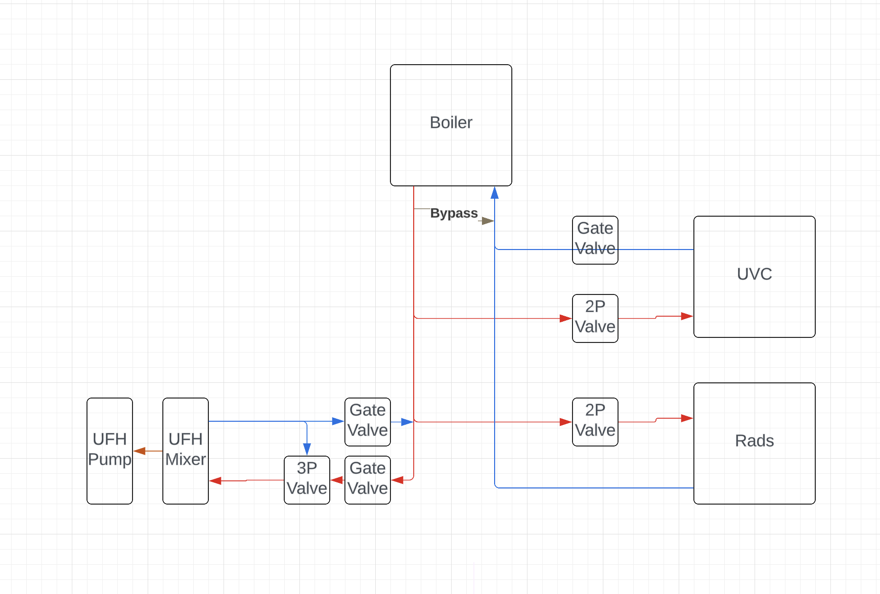
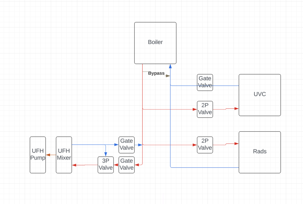
Looks similar to what I had seen in the Heat Geek videos. To ensure I'm understanding that diagram correctly; - Close Couple Tees on the flow pipe - 2x gate valves for isolation one each leg - 3-port valve to replace the existing 2 port valve, and connect the two legs ahead of the UFH pump. Which would allow the UFH pump to run as fast as it needs to, assuming it's capable of doing so (Grundfos UPS3), and would look something like this; The biggest differences between this and the Heat Geek videos, that I can see, is; 1) they suggest a gate/lockshield valve to connect the two legs, opposed to a 3-port valve, and to balance that to the same DT as the rest of your system (DT20 for me) - still balancing the UFH loops down correctly further downstream. 2) The UFH would be "returning" into the flow pipe, so anything downstream to it would receive a lower flow temp (in my case that's probably not an issue, as the rads and DWH are teed off earlier). 3) When the UFH mixer closes, whilst the 3P Valve is still open, the flow has no where to go. I assume that would just trigger the bypass at the boiler earlier, so is acceptable? I don't quite understand what the close couple tees do opposed to just fitting the 3P valve alone, is it so if the UFH pump does start to suck, it will most likely suck from the UFH return and not the Rads/DWH? That doc also states; Why does the 3-port valve need to be open for the rads? I assumed, in my set up, it would only need to be open when the UFH is calling for heat and the rad circuit would behave as standard.
-
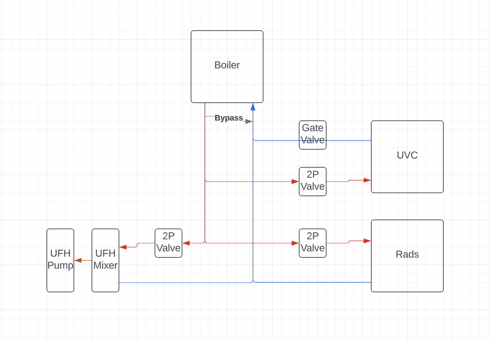
Ah I used DT20 for the UFH flow calcs. I was using Flow Rate (LPS) = KW / (DHC * DT), so Rads 6.2kw / (4.2 * 25) = 0.059 LPS (or 3.54 LPM) UFH 10kw / 4.2 * 7) = 0.34 LPS (or 20.4 LPM) Total requirement, minus DWH approx 24LPM which is more than the boiler pump alone can supply. Currently looks something like this; DWH and heating can be on at the same time, the boiler doesn't have priority hot water, nor differing temps for water/heating. I'm looking to make the best out of the boiler we have rather than considering replacing it - when I do, it'll be for a heat pump. The way the Baxi Weather Comp works is by using a curve if it's only rads/UFH calling for heat, but boosts to max flow temp as soon as the DWH is calling for heat, which is why I need to keep there UFH mixer has a fail safe. It was this clip, at 11:55 that suggested the CCT at the UFH end - https://www.youtube.com/watch?v=mNcRx45DQ8M

-
Current setup; 32kw Baxi Platinum+ System Boiler, with weather comp, fitted upstairs, believe max flow rate is 20 LPM. 250L UVC (same cupboard as the boiler) assuming 3kw requirement. Upstairs rads, heat loss approx. 6.2kw. Rads spec'd for DT25 (lowest I could reasonably go) Downstairs UFH, heat loss approx. 10kw. 150mm centres. All single zone. Automatic bypass valve fitted before any zone valves/pumps Boiler was spec'd by plumber before I had even heard of BuildHub and therefore pre-renovation. So it's massively oversized for what we now need. Currently all 3 are separate zones with their own zone valves and pumps. The boiler, rads and UVC were fitted by a plumber, the UFH came as a kit, including zone, pump and mixer, that I fitted myself, the plumber just left me the flow/return pipes to connect the UFH to. I've never been convinced the system as a whole has been running efficiently. When the UVC is calling for heat, the boiler flow rate goes to max (approx 80c), otherwise it runs on a weather comp curve. If my calcs are correct, for a system running at DT25, I'm assuming the UVC will require a max flow rate of approx 1.8 LPM, the rads will require a max flow rate of 3.54 LPM and the UFH requires a max flow rate of 5.7 LPM, resulting in a total max flow rate of 11.04 LPM. Which appears to be well within the capacity of the boiler pump. Long term my aim is for an ASHP to be, near enough, a drop in replacement when the boiler eventually gives up the ghost. I've been geeking out of Heat Geek videos recently, especially with regards to hydraulic separation and the dos/don't of close coupled tees on UFH systems. So my questions are; - Should I remove the UFH and/or UVC pumps and let the boiler pump do its thing? Feels like they're all currently competing against each other, and just feels wrong? - Should I consider fitting a close coupled tee, and lock shield valve balanced to 25DT, just before the UFH mixer? Videos that got me thinking, in case anyone's interested; https://www.youtube.com/watch?v=mNcRx45DQ8M https://www.youtube.com/watch?v=K_OWE2dJht0 https://www.youtube.com/watch?v=Gk4Mzvcaen0
-
We had rotten floor joists so replaced with a slab and UFH. Fitted 100mm PIR as advised by a builder at the time, and wish we'd gone thicker, will be doing so for the extension. It's certainly no more expensive than rads though, and IMO is a far superior distribution of heat.
-
Diathonite is mixed with NHL5, so if breathability is what you're looking for, that ain't it. Given you already have pebbledash externally, is external wall insulation an option? It's far "safer".
-
Could be a real faff if finishing with compriband.
-
How old's the house? Looks like it could be solid wall construction, especially as the plaster looks like it could be lime... Is the render cementious? You could have a crack/leak in it (that's saturated the wooden lintel (?) ) and the only way for the water to go is inwards.
-
I showed BCO my spreadsheet with the per room flow rates, they haven't, yet, asked for anything else.
-
What size Hot Water Cylinder for family of 5?
jayc89 replied to Meabh's topic in Boilers & Hot Water Tanks
Whilst we were down to 1 bathroom and were showering "serially", 250L was fine for us. When our old ensuite was still functioning, 2x concurrent showers would drain the UVC. When we refurb the bathroom, which is where the cylinder is located, I plan to swap it out for a 400L one, joists allowing... -
Loops are fine, they allow for max flow. Assuming an unvented cylinder, you need to be careful to avoid back pressure from any mixer taps, so you'd want; 1) a PRV on the mains coming in, before the cold manifold 2) a NRV on the supply to your hot water manifold
-
I bought mine from Travis Perkins for 40.96 each
-
I paid 40.96 each for my HEP manifolds. (end of last year)
-
Insulating MVHR Ductwork in the loft
jayc89 replied to richo106's topic in Mechanical Ventilation with Heat Recovery (MVHR)
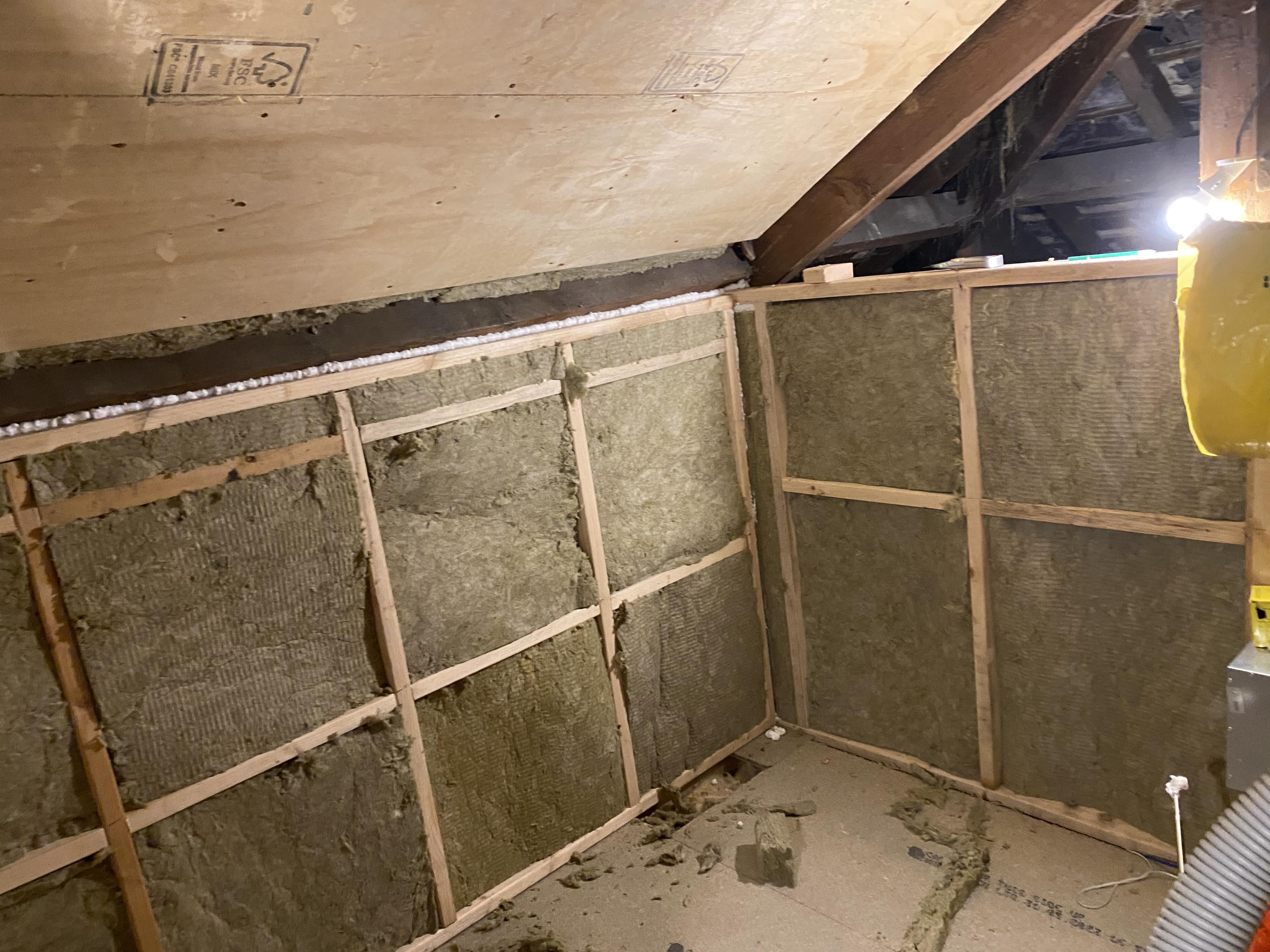
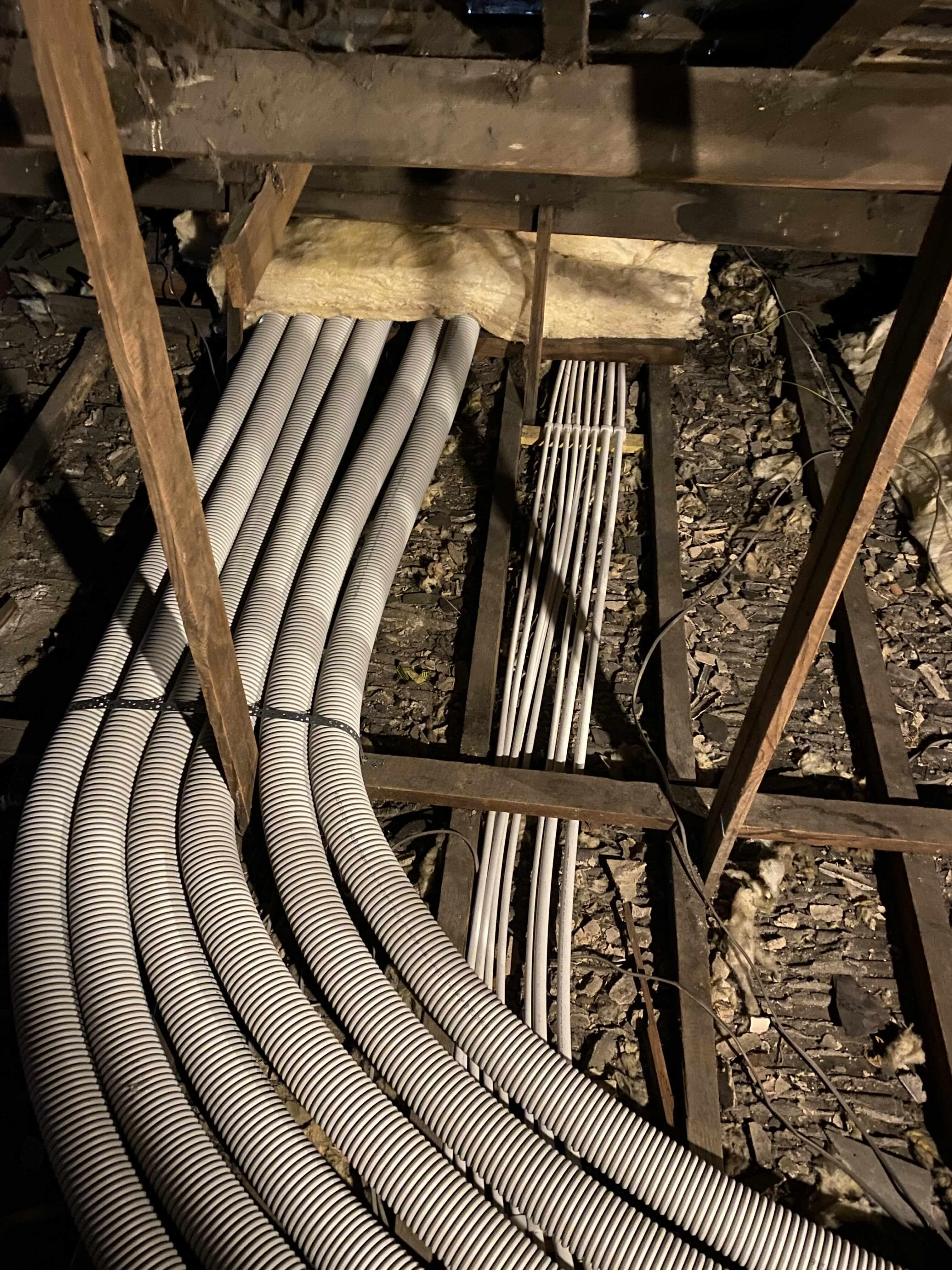
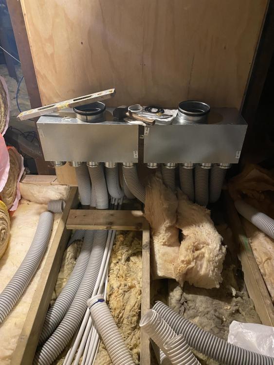
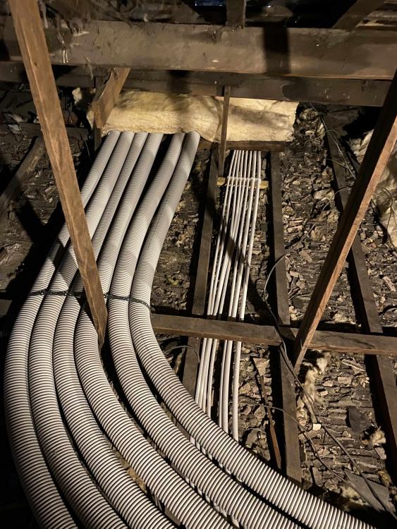
I ran them under the loft insulation and built an insulated "room" in the loft for the MVHR unit, water manifolds and any other, lightweight, plant I may need (comms etc)
-
Installation cost
jayc89 replied to Mr Blobby's topic in Mechanical Ventilation with Heat Recovery (MVHR)
It probably took me a week to run 7x supplies and 8x extracts in my renovation, that was traversing solid joists, hiding them in stud walls etc. fitting all the plenums (inc. sealing the first floor penetrations), creating a stud wall to mount the 2x distribution boxes on and hooking everything up. Certainly DIYable, but it depends how much you value your time, £1,500 isn't a massive amount in the grand scheme of things and it could allow you to be cracking on with something that's far more expensive to have done by someone else. -
I just press the right arrow across to "holiday" and then press the tick, drops it down to 12c (I think) until it's cancelled.
-
It shouldn't really leave the pan off the wall much at all, just to fill the undulations of the tiles/pan, allow for full contact and a longer lasting seal than your typical bathroom sealant.
-
I squirted a load of CT1 behind my pan, tightened it up and wiped off the excess with baby wipes. Once the CT1 had cured I went over it with a bathroom silicone.