Moonshine
-
Posts
2094 -
Joined
-
Last visited
-
Days Won
6
Everything posted by Moonshine
-

Dipping a toe into MVHR
Moonshine replied to Moonshine's topic in Mechanical Ventilation with Heat Recovery (MVHR)
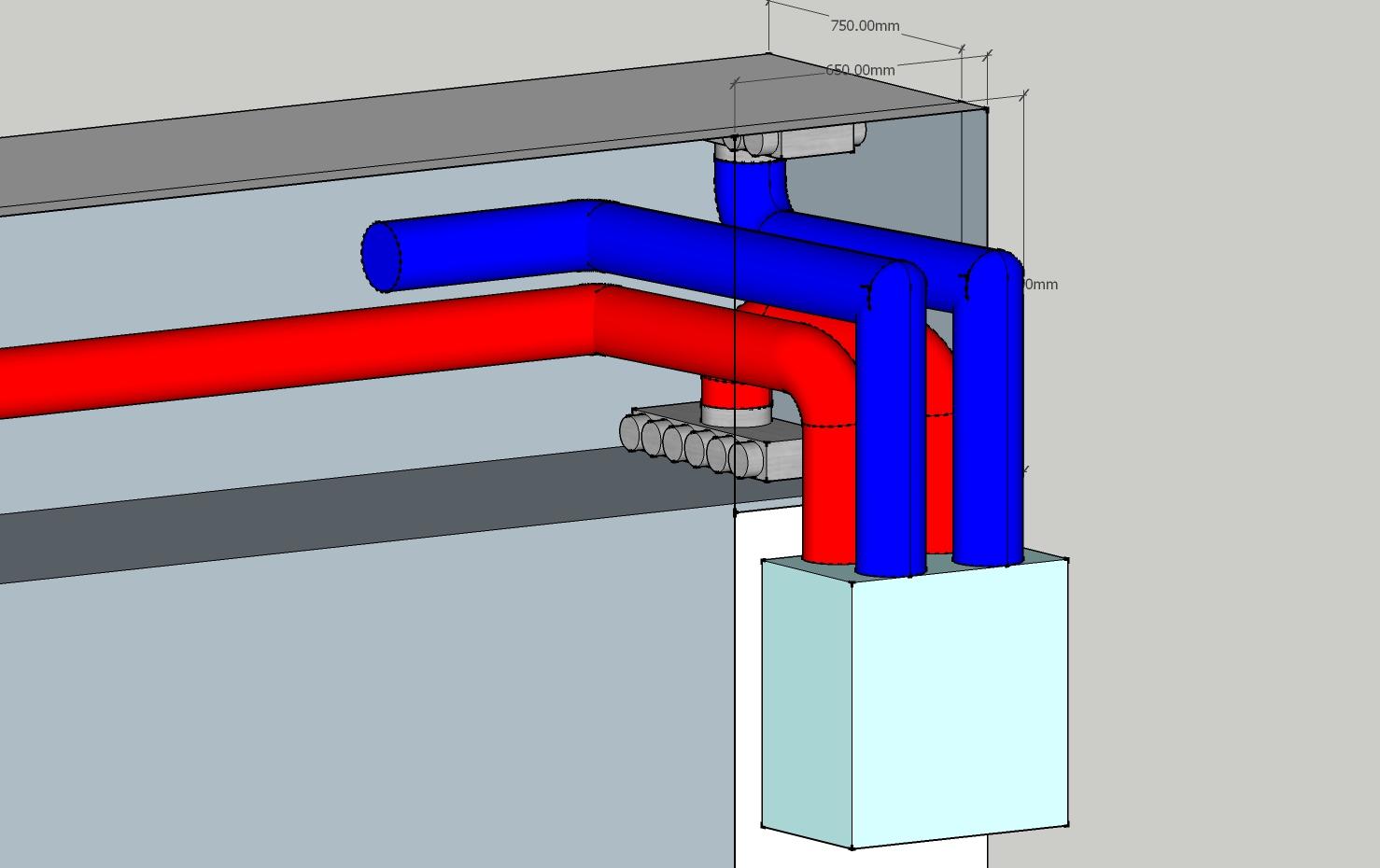
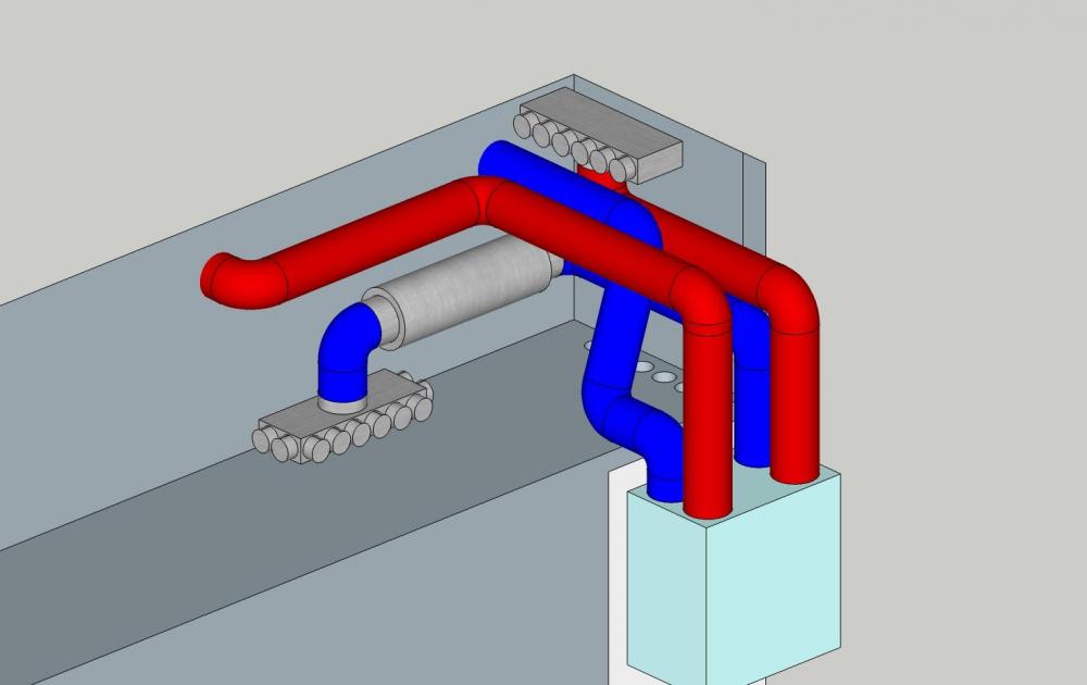
The silencer is not typically required on the return air, and looking at the noise data for the MVHR return is 9 dB quieter than the supply side, so i have just put a silencer on the supply, with a 10 port manifold for supply (may only need 8) and a 6 port manifold for the return. So a couple of tweaks of getting a silencer on the supply side, as below. Its a mess and too cramped in, with the silencer tight over the ground floor riser, and the silencer going through a 100mm internal wall, also there is a ridiculous long extract so have tweaked it to be (a more space efficient design may be achievable with different manifolds, but its enough for now); This gives frees up loft space / maintenance, gives 275mm clearance over the riser, and 1m between atmosphere pipes on the facade. In addition, all ducts are 150mm, and for the MVHR model quoted they are 125mm so some clearance tolerances allowed for.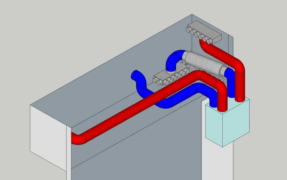
-
The sad thing is, in this current timeline i really can't tell if that is satire or not!
-
I can almost smell the British sovereignty in that picture
-
Dipping a toe into MVHR
Moonshine replied to Moonshine's topic in Mechanical Ventilation with Heat Recovery (MVHR)
Good points, which ducts need to be wrapped in 20mm? the 150mm atmosphere side ones? Bends are going to be tight, and may need to put rigid 90 degree bends for the ducts from the floor manifold going down the riser. Something else i haven't factored is silencers on the room side ducts (supply and return), between the mvhr and manifolds. These are typically 600mm long, with a further 150mm allowance. With the current layout these won't fit and a re-design is needed to fit them in the space. -
Dipping a toe into MVHR
Moonshine replied to Moonshine's topic in Mechanical Ventilation with Heat Recovery (MVHR)
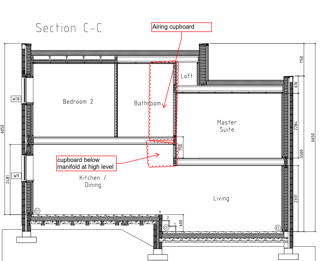
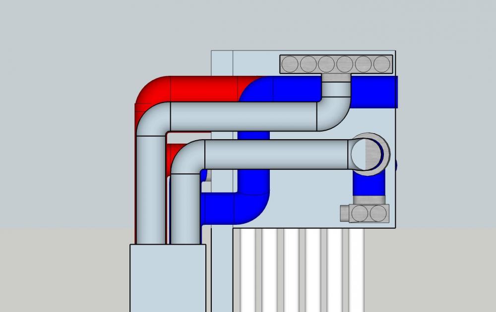
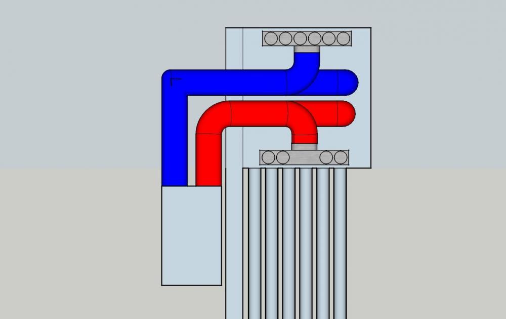
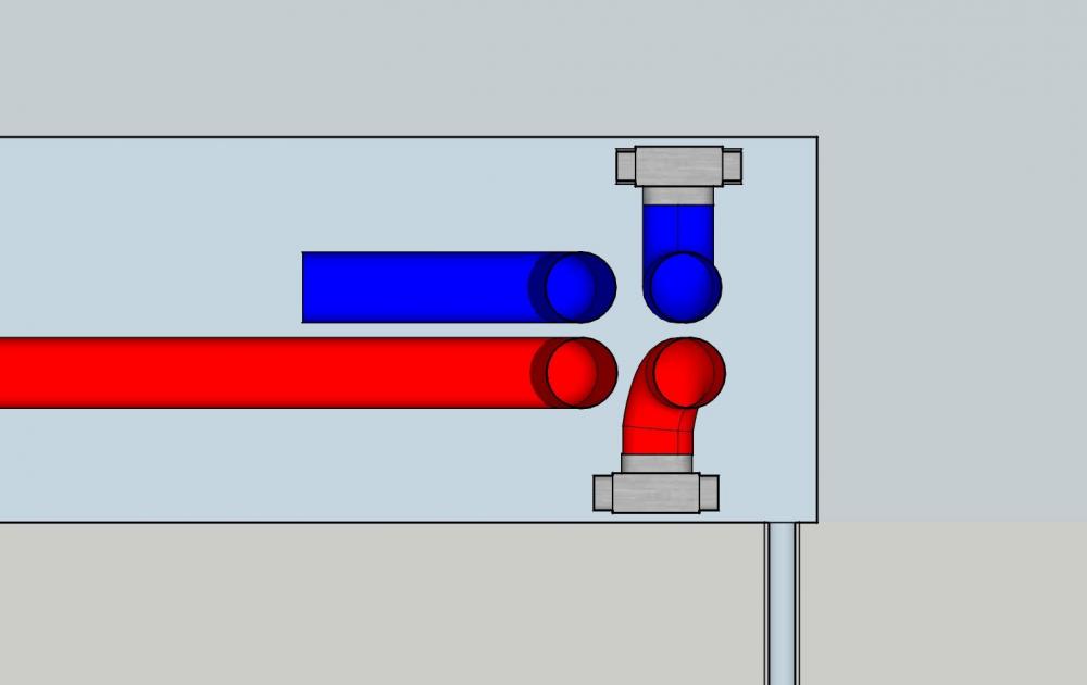
I have been giving this a bit more thought and have sketchup'd the following arrangement in 3D, with the MVHR in the airing cupboard, and ducts running down a riser It seems that it works (Just!), with the return manifold on the floor, and the supply manifold on the the ceiling, as below Section through loft (short section) Long section through loft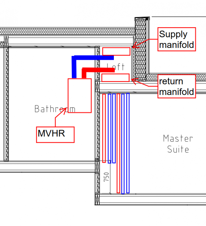

-
Dipping a toe into MVHR
Moonshine replied to Moonshine's topic in Mechanical Ventilation with Heat Recovery (MVHR)
absolutely -
Dipping a toe into MVHR
Moonshine replied to Moonshine's topic in Mechanical Ventilation with Heat Recovery (MVHR)
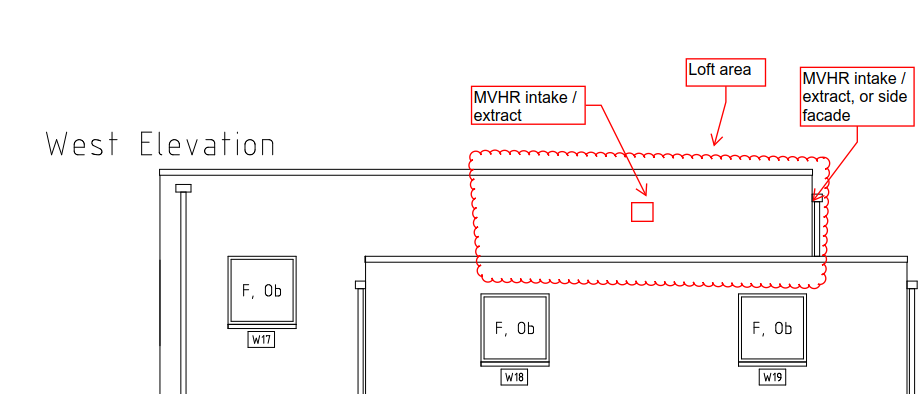
That is a new bit of information, thanks. I assumed best to be on separate facades to stop mixing, looks like they can be both on the west elevation with a decent (> 1m) elevation. -
Dipping a toe into MVHR
Moonshine replied to Moonshine's topic in Mechanical Ventilation with Heat Recovery (MVHR)
tbh i want to minimise the amount of roof penetrations as its a flat roof and paranoid about leaks, my plan would be to take them out of the exterior walls of the loft area on separate facades as below. The Loft is looking as though it is going to be a MVHR duct area.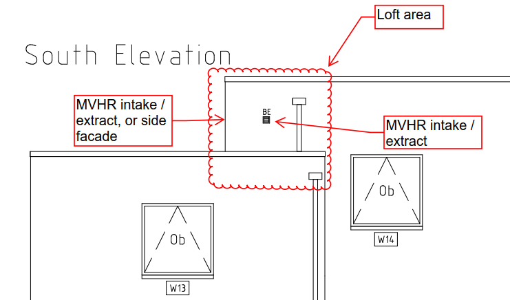
-
How high can those lifters go? Oops didn't see the 4.8m!!!
-
Sealing between wood and plasterboard - what silicone?
Moonshine replied to oranjeboom's topic in Decorating
Why not just standard decorators chauk? It has flex to it, so will allow some movement. -
Dipping a toe into MVHR
Moonshine replied to Moonshine's topic in Mechanical Ventilation with Heat Recovery (MVHR)
I think that i have mis understood that part then, so its one manifold for return air, and one for supply. In that case i think that it could work by having the MVHR in the Airing cupboard, with ducting to the loft above to the side (see section C-C above), and both the manifolds in that loft space (may be tight! its 750mm x 800mm section), and then i put a boxed in riser in the master suite which will take a number (no. 5-6) 75mm flexi ducts down to the joists of the floor below for supply and return air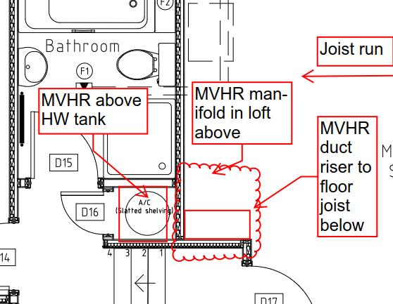
-
I spoke to a alu window manufacturer today, they said the same, that those windows and frames are going to be circa 160kg each and the frames below won't support it. It was either their windows with some kind of structural steel under each window to support, or a full blown supplied and installed curtain walling system (that they don't do). My thinking is the cost will be lower with the window option with a steel support, buts its a question of how to do it, without large horizontal sections under each window, plus where the steel will be supported! time to get my thinking cap on, and seek the advice of a structural engineer.
-
The planning officer has been pretty good (if slow) so it may happen, but...... i wouldn't be surprised if it didn't
-
interesting, so if i did go back in to planning (there are some tweaks that may need doing) and state that it was going to be a phased development then i could get out of paying CIL on the house i wasn't building yet, but the planning for all houses is enacted. Edit: i have just spoken to and e-mailed the council if i can split the CIL liabilities as per the existing planning permission, lets see what happens, not hopeful but best to try.
-
Good news, the council have issued a revised CIL liability letter for the amount I was expecting. Still a WTF letter, but better that it was!
-
This is exactly it, and it's for two houses, one is CIL excempt as we will move into it, but we have the very real factor, to build it we need to pay the CIL for the other one even though we won't be building it straight away. I am looking for a way I can apply for the two houses as separate planning applications, one that doesn't get started, but don't think that will fly.
-
Dipping a toe into MVHR
Moonshine replied to Moonshine's topic in Mechanical Ventilation with Heat Recovery (MVHR)
I am thinking that maybe the MVHR unit can go in there, but the manifold (first floor) can go up in the mini loft as below, and the ground floor manifold would go in the cupboard below at high level, so that would only be two trunk large ducts going down before the octopus legs spread out.
-
Dipping a toe into MVHR
Moonshine replied to Moonshine's topic in Mechanical Ventilation with Heat Recovery (MVHR)
yep that is the stage i am now. The floor plans as they stand rely on a standard ventilation strategy, and i want to see how much compromise is needed if MVHR was used. -
Dipping a toe into MVHR
Moonshine replied to Moonshine's topic in Mechanical Ventilation with Heat Recovery (MVHR)
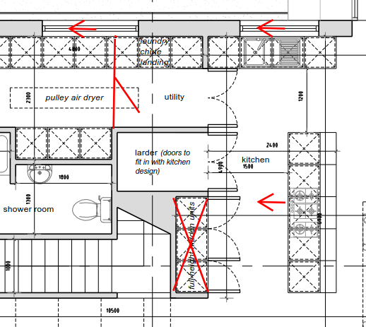
Thanks both, especially those pictures. I have attached some very rough marked up drawings of the house plans which is where i think the duct runs may have to go, as well as the joist orientation. I am proposing that the airing cupboard is uses as this is on the first floor and has the smallest atmosphere supply and extract runs. I think that its going will be very tight to accommodate the MVHR and also manifolds. Any comments on the layout and better siting for things (note, there is a mini warm loft area above the master bedroom which could accommodate a manifold, and atmosphere supply and extract runs. floor plans - 200220 - MVHR.pdf -
Dipping a toe into MVHR
Moonshine posted a topic in Mechanical Ventilation with Heat Recovery (MVHR)
I am thinking of installing MVHR in my proposed house and have a quote from BPC for the kit (no design provided). However for my own curiosity and to try and determine the PITA factor, i want to see how feasible it would be to integrate into my current house design. Its using I-Joists so i would want to minimise the penetrations through these, so starter questions. Where can i put the MVHR unit? is an airing cupboard suitable? What are the typical duct sizes that need to be accommodated? is it flexi duct? Can ducting be rectangular? Where in a room do supply vents need to be located? e.g. room centre? for toilets, does the MVHR constantly extract at 15 l/s or is there a boost based on the light being on? -
Internal Walls on Floor panels or direct on the joists?
Moonshine replied to MikeSharp01's topic in General Joinery
What is one of those? and is it needed on internal floors? As for the boarding out, i have only ever seen boarding done over the whole floor level first. -
Drawings ready for the pre planning.
Moonshine replied to Mike_scotland's topic in Planning Permission
I was thinking something like below, gives approx 600-800mm extra width to the living space, and retains the full height cupboards (kinds off) and larder size. HOWEVER the stairs may need to go over the 'full height' cupboards to get the left to right rise.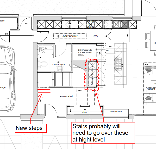
-
Drawings ready for the pre planning.
Moonshine replied to Mike_scotland's topic in Planning Permission
Fair enough, though that shower room is looking a bit lardy / fat, and if you took a bit off that you could keep the larder size, could these cupboards be sacrificed, and the shower room re-shaped? I think these areas were nice to have when the house was 1.5m longer, however now the house has been shortened things need to be condensed a bit to maximise the important internal areas. Do you really need two doors to the garage from the house? if you loose the one from the bottom of the stairs, and have the shower room door on to the utility then this may allow the stairs to be redesigned with a couple of stairs at the bottom, then a quarter turn in the corner. The effect of this is that the stair run towards the kitchen would not be so long, and allow the kitchen to be wider.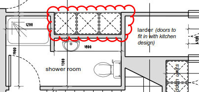
-
Drawings ready for the pre planning.
Moonshine replied to Mike_scotland's topic in Planning Permission
What i was proposing would keep the 1500mm between the stairwall and the island, as the 600mm full height units would relocate (Exterior wall) and larder would get smaller, and storage put under the quarter turn of the stairs. -
Drawings ready for the pre planning.
Moonshine replied to Mike_scotland's topic in Planning Permission
Think about this from the outset though, as if it eventually becomes a habitable space you will want to get things in place now rather that later retrospectively (e.g. thermal envelope) thinking about it this is what i would try to do, move the counter and cooker 600mm to the left, loose the full height cupboards from this location (cupboards could be put below the quarter turn of the stairs. Truncate the size of the utility room, and loose the current larder, to create more of an larger L shaped kitchen and play with this type of layout, the full height cupboards could go on the exterior wall.