SimonD
-
Posts
2175 -
Joined
-
Last visited
-
Days Won
13
Everything posted by SimonD
-
That's actually what I do when I have a space like a hall or landing and when I have rooms with large open plan openings, so I create a non-existent door - as long your room dTs match, and set to 0 then it doesn't impact the fabric losses. It also shouldn't affect the ventilation losses because the exposed envelope is set and the calculation uses that. It's a bit prescriptive on the ventilation, so there isn't anything immediately available to make adjustments to this ventilation factor. There are still some questions about how BS EN 12831:2017 treat ventilation and the CIBSE guide uses a bit of SAP in there. I'm going to have a think about this one. It's really the way it's calculating infiltration leakage which is giving you the high figure, but you've got to be a bit careful how you interpret the Ventilation - Emitter Sizing. This calculation isn't saying that you are going to use this amount of energy at a given time, which is your Fabric loss and Ventilation - Generator Sizing. The Ventilation - Emitter sizing, although provided as a total, should really be looked at in relation to individual rooms because it's essentially calculating the effect of high winds on each room based on the exposed area. So at any given time the rooms won't be losing all heat to the outside, but transferring to other rooms within the building. But high infiltration will increase the heat load within the room subject to high infiltration and so the standards are encouraging us to install slightly larger radiators and thus improve efficiency. Does this make sense?
-
No worries. Thank you!
-
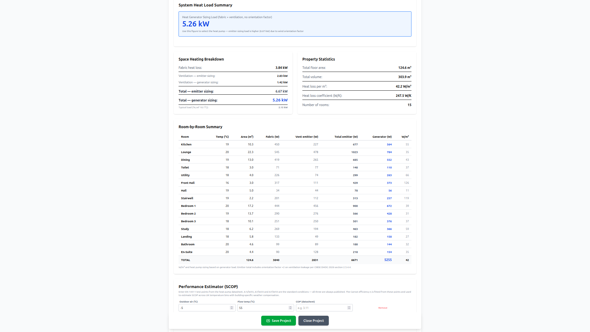
Here you go. This is a lot better. Not quite there yet, but about 1/2 of what you were seeing, but as you can see the calculated fabric losses of 4.22kW are much closer to yours, but this is at -4.6 which is the conservative MCS post code lookup: In the rooms editor, there is a column labelled Design dt (C). When you add a new element, it default to the Design dT of room temp - outdoor design temp. Then next to it is another column for ref dT which is the default delta T between room temp and Typical Outdoor temp. For all internal elements this needs to be set to the difference between internal rooms, or 0 if there is none. I've just gone and updated all your internal settings to this, which has made the difference. I may have incorrectly amended some of your insulated ceiling which may be external? I've then gone and change the outdoor design temp from -4.6 to -2.5 and as you can see, the fabric loss is now down to 3.84kW and generator sizing is 5.26kW: The total emitter sizing is quite large compared to what you're experiencing with your low flow temps etc. which means I need to dig into the calculations to make sure I haven't got something wrong in there, but I suspect that because of the way it has been implemented, there's been a cautious approach taken by CIBSE in how they've implemented the new method. It wouldn't surprise me and is actually a good thing as it's better to upsize rads for worst case scenarion and reap the benefits of lower flow temps over the long term. But I will need to check. I'd also recommend you go over your element inputs just to check the assignment of U-values from your U-value library and some didn't quite match. Hope that helps?


-
14.83kW emitter sizing load? That seems massive. Something doesn't seem right there. Do want to show some of the room inputs? Or PM me screenshots?
-
No, not stupid at all, just something you need to get your head round for heat loss calcs. In the 2 story: - Ground floor gets 1 x Ground Floor (Slab) or (Suspended) + Ceiling - 1st Floor get 1 x Floor + Ceiling You're not really double counting because if both rooms have the same design internal temp, the Design dT is set to zero on both the ceiling of ground floor and floor of 1st floor so there are no losses between them. If there is a difference in internal temp, you just need to keep in mind that the Design dT becomes either + or - the difference. So if one room is 21C and the other 18C, it's +/-3 either way on floor & ceiling. You'll not know this now because the standard U-values aren't in the global database yet, but one thing to keep in mind is that the floor always has a lower U-value than the Ceiling for the same buildup - The CIBSE standard for plasterboard, joists, floorboards, with 100mm insulation is 0.32 I think. The same buildup as a floor is 0.25. Hope that clarifies it?
-
Shrinkflation and filling gaps in plasterboard
SimonD replied to SimonD's topic in Plastering & Rendering
Clearly, I've never measured them properly to begin with 🙄 My assumption was that as with timber products which is what I'm more used to working with, or pipes, you get what's specified. And maybe it explains why I had to get rid of the plasterer I was using? I was just told that gaps above 3mm must be prefilled, nothing about leaving a gap when boarding but he and another did most of the boarding so far. Oh dear! -
I've just plaster boarded up a ceiling and while doing so realised that plasterboard sheets seem to have shrunk? First I thought it was either me or my tape measure and then I twigged the sheets are all actual 2395mm and not 2400 long - my mistake was not taking this missing 5mm into account when I cut short ends of the plasterboard. So rather than waste a load of sheets, I now have some very annoying gaps in my ceiling. Main question is: what should I fill these gaps with? Drywall join filler or some expanding foam? My sense is drywall filler is more sensible. The other thing I also realised is that all my sheets are 3mm less than 1200mm some along both the walls and ceilings the screws get closer and close the batten/stud edge. Is this sheet dimension new or have I just been blind to it before?
-
Windows or Linux machine? I'll test on my windows 11 machine to see if I can replicate. And put it in the bug list for further investigation.
-
32.6/66.2 (although you can just use room internal measurements) = 0.492
-
Hmm interesting. The card you should be seeing looks like this: I wonder whether you have the older version of the app from before I sorted the radiator saving issue locally. Can you close your browser and/or do a hard refresh? On both my browsers - Chromium and Firefox, decimal entry in the form I have is fine from keyboard. and I have the add & select button rather than add to database. Would be interesting to see what you get following full refresh. Ah, no sorry! You're in the Radiator Library editor on the multi project beta! So the card is correct. Inputs on both my browsers work fine for decimals on water content. What browser are you using?
-
Yes, of course, share the numbers.
-
Best thing to do with odd shaped rooms, it just calculate the P/A ratio yourself and enter it into the calculator. In the Floor Dimensions and Exposure Card, select Manual P/A, then measure the length of the exposed perimeter of the room and divide by the total floor area - then you can just add the p/a ratio into the Enter P/A Ratio Directly - this is specifically designed for complex shapes. You can the ignore all the other dimension inputs in that card. Hope that makes sense?
-
Because this is an implementation of the CIBSE reduced method, these are really the only choices for this particular version. However, when I get the full BS EN 12831:2017 method tested and run, there will be full freedom for proper and complete fabric inputs for the calcs. The CIBSE method covers pretty much 90% of projects we see, which is why I went for the quicker win to begin with. The tool will still give you a pretty good result right now as fundamentally this gives you a conservative result as that's what all the methods tend to do. However, to get around this now, you can select the tab to the right of SAP Estimate and select the Measured/Tested air permeability and then add your SAP design figures, that completely gets around the problem and is the better approach right now.
-
It is, and applied well and in the right place, it produces an extremely good finish. I've been in many houses where it looks stunning. A lot of the other paints like the trade ones are developed I think to go on easily and hide a multitude of sins.
-
Absolutely, they are all about the surface area, which does dictate output. The app just uses the shortcut of the Delta T 50 and then applies a correction factor for the system design temps, so we don't need to worry about the surface area being involved in the app. We could, but it was enough to resolve the UFH output calcs as they are calculated based on the variables input for each room and those took some effort to resolve and get right - or at least in the ballpark. If there is enough call for it, I may add a calculator based on surface area for rads as I know the question comes up a lot with older existing panel rads with no fins. It's in my backlog. Yes, that's what I should have said ...
-
Thanks for letting me know. That's my fault. I was playing around with users and authorisation earlier to create the new beta engineer test and in doing so seemed to break how radiators are saved to specific users - it was saving fine for anonymous but not any registered users! Anyway, it should be fixed now 😊 Yeah, the width is actually termed length in catalogues so you always have dimensions = height by length e.g. 600x1200 or 1800x445 Glad to hear you're getting on with it okay!
-
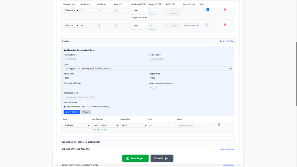
Any radiators you add go into your own 'company' radiator database linked to you as a user, so if you had several projects, you'd build up your own database of radiators. Nobody else has access to those or can edit/change them, they're yours. In the wider version for managing several projects, there's even a project settings page where you can add edit and delete you own database. If you want access to this wider version with multi-project capability, ping me your registered email address and I'll change your settings to 'beta' test engineer in the system. I'll add flat tube radiators to the type as a system addition, but for now, two column would work fine - the type doesn't really matter that much, it's more for your own reference. The important bits are output at DT50 and water volume really. And then size if you're putting a new one into a space... Not at all, I've done that to check volume on existing rads myself, but luckily most rad manufacturers now provide l/m figures in the tech spec. Stelrad actually even provide Kv. To get the l/m min take your total measure volume and divide by length in meters - so in your case the 0.578m Best thing to do in the workflow is add all your standard elements into the U-value tab and create your U-value library. Do this especially for all your floor U-values by using the Floor U-value calculator as floor U-values vary according to the Perimeter/Area ratio. Once that's in you'll get an automatic drop down when you add an element in the rooms tab. These will then auto-populate and add the thermal bridging addition. I've been back and forth on the editing of value directly in the room as if you skip creating the U-value library and you're working on a large project, inputing into individual room elements gets very tedious, which is partyl why I locked it to force users back to the U-value library. I ought to put a user hint in there about this. The other bit to bear in mind here is that if you add a door or window to the room, you'll get another automatic drop-down where you can select which element area this door or window needs to be subtracted from. So if you have an external wall added, this will be listed in the dropdown and you just apply it. The reason to do this is because this will apply the correct calculation for fabric loss, but at the same time used the full external element area for the ventilation & infiltration calculation. To make things easier to follow, I tend to add the wall element, then add any corresponding window or door to that element and subtract it. Then move onto the next element. Then in the elements also remember to change any internal element's Design Delta T (e.g.partition wall) to the difference between the two adjacent internal spaces and not leave it at default. Elements roof, ground floor suspended, external wall are all automatically added to exposed envelope so if you have a ceiling that is the external envelope, then you need to add this to exposed area by selecting Exp. I have on my to do list a load of videos to walk new users through the tool. If you spend a lot of time inputing this stuff, it follows pretty much a normal design workflow but it's not obvious at all for someone not in the industry.
-
Ah okay. The finished Readme is now up on Github so should contain all you need to know for Linux install: https://github.com/OpenHeatLoss/OpenHeatLoss You'll notice in the Readme that while the UI is completely functional there is room for improvement especially for mobile and accessibility. With the amount of input for a design, I'd hesitate to use it on a phone unless I was just accessing it for reference and using the survey checklist. But obviously it's all ready to go with the hosted service
-
Is this for installing locally from Git or using the hosted version? If installing locally, it's currently designed to work as a web stack using React/Express/Postgresql, so you'll need to install those and access it through your browser. Initial development was on windows, so it can be installed on a windows machine, but the majority of the development has been on Linux as that's what all the hosts use. The hosted version is best through PC & browser, but it will work on both tablet and phone through browser. I'm currently completing the Readme for Git which will guide you through the setup for self-hosting.
-
yes and with some controls they're intelligent enough to balance load between 2 units to keep them both in more efficient operating conditions, or separate dhw from ch.
-
Either or, whichever is easier for you. I'm happy to be fully transparent about any issues or problems as well as suggestions for improvement but email certainly helps me to collate them into relevant patterns. Thanks!
-
Yes, a cascade is 2 or more units connected together. An advantage of a cascade in a large domestic situation is modulation as a very large single unit may not be able to modulate down low enough and therefore cause short cycling during mean temperatures. But this is entirely decided through design of the system and what your typical outdoor temperature is compared to the coldest design temperature. There are obviously other considerations to cascades v single units, but this is a big one. Some manufacturers like Nibe design their cascade systems so you can add new units onto to older ones etc. over time, or even run ASHP with GSHP and pool heating. There is more complexity in the commissioning and control of a cascade. 3 phase shouldn't really be an issue for the heat pump installer. The 3 phase units I've seen are very easy to wire up and it's really up to the electrician (I get my electrician to do all the mains connections because he's got the necessary crimping tools for the terminal connectors and testing tools etc.) including then balancing the phases.
-
Plenty of those around on 3 phase. In fact some of the larger units are only available in 3 phase (e.g Panasonic M series over 12kW), but it all depends on the system design and whether single big unit or cascade is the better way to go. You need a good designer to look at it and justify the decision.
-
I'm actually not sure where the best place is to post this but as it's primarily about heat pump system design, I'll put it here. @marshian and @mads ,and maybe @MikeSharp01? you've expressed your interest so mentioning you here too. I hope the admins don't mind me putting this up here, but maybe if it is found to be useful, could be pinned to help so many of the people who come here struggling with poor heat loss calcs and designs and want to complete their own. I've finally deployed the tool I've been working on for initial public use. It's available free and open source, so repository on GitHub if anyone wants to host locally. It's currently in a bit of a test mode so I can get some feedback and bug reports to refine it and add further important functions. Just bear in mind I've been developing this myself along with everything else in life and it's been quite a major piece of work since last summer. It is now based on the CIBSE 2026 Domestic Heating Design Guide implementation of BS EN 12831:2017 and BS EN12831:2017 so complies with MCS design requirements. I have been using this tool for MCS heat pump projects in house that I'm doing. It's at https://openheatloss.com Important user notes: At the moment when you arrive, you can complete a whole project anonymously without logging in but this persists only for 48 hours or until you close the browser. The save a project, just register using name and email, nothing else. If you want to remain largely anonymous, you can just add the post code prefix to the installation address to set outdoor design temperature and Typical reference temperature. No need to put in loads of personal information. The workflow design is to work you way from left to right across the app tabs. Current limitations: I have not populated the database with standard wall build-ups and U-values. If you're a self-builder or doing major diy hopefully you'll have this info already for your project, otherwise you'll need to look it up manually. There is, however, a comprehensive floor u-value calculator and a simplified one in the room elements input too, so these can be calculated for you. Same thing with radiators - no standard sizes or outputs in a global database yet. I will do a scrape at some point. All outputs entered should be the Delta T 50 catalogue values and if you want system volume calcs, also input the radiator water volume. The UFH sizing calculates volume automatically based on your set pipe diameter, spacing and room area. Text based design - I've tried some of the design tools that are trying to be like cad design software, so you've got do draw your project. Having used cad software, I didn't warm to any of them because they're not proper cad software but in house bespoke design. As I also found out they have limitations so you have to fudge some shapes - roofs in particular. Text based means you can input elements more flexibly according to your needs. Well, I hope so anyway. What you will find different if you've used other tools, although I'm sure they'll either be doing it already or soon, is that the tool provides 2 different heat load figures. is for the heat generator which calculates the whole house fabric and normal ventilation includes a full fabric air infiltration calculation and is usually higher than the generator load To explain this, the new heat loss calculation methods according to BS EN 12931:2017 and specifically those implemented in CIBSE 2026, with wind load under certain conditions, parts of the building and rooms may require higher heat outputs, whilst other parts may need less. This 'total' value comes to a higher result than the generator. In my own test projects that I've run through the new software, I can attest to this working quite well. For example, in one design and installation project of mine, one particular room in the house was designed for 23C but over the winter, whilst never cold, the room never managed more than 21C. I had thought it was a balancing issue, but no. When I ran this project through the new software it predicted that I would need larger radiators in this particular room, base on the new ventilation infiltration calculation, so that is what I will be installing before next winter. Anyway, please have a go and let me know what you think, and ask any questions you have here, or email me at the tool - heatloss@openheatloss.com Does anyone need a user guide to the design workflow and inputs? Let me know..
- 59 replies
-
- 14
-

-

-
It's funny you should raise this difference between heat pump installer and electrician. The electrician I use as part of all my heat pump installations called me a while ago pretty p***ed off. He'd completed a new house wiring installation plus solar & batteries on 3 phase. The heat pump people came along and just installed a single phase heat pump cascade, causing a bit of a headache. At least yours are talking about it. What is the size of your heat pump? And I'm guessing it's been confirmed the model is available on 3 phase? Probably a silly question. I've had a similar experience with solar design for my place where the designer didn't seem to understand modular and phased approach. It's a bit infuriating. With the right system design there should be no problem scaling up if you need to, just as @JohnMo suggests.