


SimonD
-
Posts
2214 -
Joined
-
Last visited
-
Days Won
13
Everything posted by SimonD
-
Difficult to say as there are issues with both and I wouldn't trust either of them. If you can bear the pain of re-inputting your data, you can use OpenHeatLoss.com (which I have developed) to complete a calc and design to current design standards. This also provides the ability to look at your ufh design in relation to heat loads etc. The only thing it doesn't do right now is Fan coil sizing
-
As an installer, I can tell you that many products aren't even designed for the sole benefit of the installer, but that of the manufacturer, so we have to fiddle around unnecessarily and deal with call backs, hence why you get to spend a long time finding the products you stick to. When you find the good ones you find they're for the benefit of both installer and customer.
-
Full RdSAP10 (from June 2026) construction library is now in the tool. It's under the U-value library similar to floor u-value calculator.
-
I'll need to think on this as the logical extension would be to add this function to all internal elements and party walls. It could be done by changing the workflow so that all rooms are added, like U-values, into a library and then the following the tab is elements - that way each element can be tagged for adjacent room and dT between those spaces calculated and auto applied. It would require quite a bit of change, but definitely worth mulling over.
-
Yes, I agree. That's all coming, but as an ancillary support doc/instruction videos with links from the app itself, rather than notes within the app itself. This is already there - it's a full EN 1264-2:2021 output calculator. If you input ufh into a room, when you go to emitter sizing, you can either import exiting UFH or Add New in there. You'll then see then full options available. This is currently so unusual, that yes, if I get a number of requests, I'll build it, but at present, it's on the back burner. This one is a bit of a difficult compromise. My original design did do auto save on blur, but when it was deployed to the cloud app server together with a linked database server, performance was not very good. I though there was too much lag, so lots of functions were re-scripted to calculated and produce local results for better ui/ux. The project doesn't need to be save constantly, just before closing the project of closing the browser. You can navigate between tabs and complete a whole project without actually clicking save, but for back up purposes I save when moving from one tab to the next, or when leaving the pc for a bit. Personally, I wanted to confirmation that the project has been saved when I clicked. This is probably more down to user instruction on when to save? In what sense? You can add your target design air permeability in the measured/tested tab - which could do with the addition of Design to the tab or associated note? Is this what you're referring to? Or something else?
-
Is this a reasonable cost for plumbing first fix?
SimonD replied to Great_scot_selfbuild's topic in General Plumbing
I think you must live on a different planet, Nick. I see series plumbed all the time with absolutely no thought whatsoever. Plumbers (who do very good quality work) who mindlessly just go, 'oh it's unvented so that needs 22mm to the bathroom, bla, bla, bla. Show them a manifold and the tilt function goes into overdrive and they ask wtf? Yes, radial all the time for me. And just like you, rads should also be connected through a manifold - ideally with flow regulators -
Quote for 7kw Vaillant - surely not enough?
SimonD replied to Michael_S's topic in Air Source Heat Pumps (ASHP)
No, it doesn't. All it presents are long term disadvantages and dissatisfaction for you. Even with the immersion you appear to need to compromise, and even then, if you're reheating during the day, you've got a long reheat time at just 3kW, or you're having to deal with control between heat pump to a certain temp, and apply immersion over, but then you're better off just using the heatpump to max output. There are plenty of slimline cylinders to choose from and sometimes twin slimline cylinders can be made to work. Presuming that this is as little work as required, then this hardly sounds like zero disrupt prices with zero upgrades. What have they actually detailed in the quote? As a gas install comparison, the 6.2k you're talking about is probably enough to cover a boiler and cylinder installation, depending on where you live. Sounds to me that you have too many questions about their proposal, you need to speak to others to get comparative prices. If your job is this straightforward as you say, then the other big players plus an independent are worth speaking to. -
Quote for 7kw Vaillant - surely not enough?
SimonD replied to Michael_S's topic in Air Source Heat Pumps (ASHP)
Are they proposing to plate load the cylinder? Even then, as an MCS installer myself (with the full Heat Geek training) I'd be seriously suggesting a cylinder upgrade, especially given the existing one is 15 years old and having lived with high storage temps, and given you've got them in on BUS Grant and zero VAT now. -
That's amazing, thank you very much. I totally understand where there needs to be better notation and explanation of the tool. The instructions are one of the next big steps. So too is a methods for importing measurements. I decided against Lidar as the kit is very expensive (if you don't already have the top of the range phones or tablets) and it's still a bit fiddly to work. So I'm working on a way to use bluetooth lazer measures that import into an app and can then export the data, but this may be some time. U-value data is being structured and imported as we speak, so maybe there by next week. And then next step will be the radiator library too. Noted on the links to room below or above as you have to hold that in mind quite carefully while inputting the data. I tried one other app that did this is a semi drawing/semi text way and it fuddled my mind - I found it even more difficult than without the facility, so need to give it some careful thought on implementation. But thanks again for your input.
-
Quote for 7kw Vaillant - surely not enough?
SimonD replied to Michael_S's topic in Air Source Heat Pumps (ASHP)
Are you going for Zero disrupt? How many people is this cylinder serving and do you have any data yourself on hot water usage? -
Quote for 7kw Vaillant - surely not enough?
SimonD replied to Michael_S's topic in Air Source Heat Pumps (ASHP)
The Aerotherm 7kW catalogue output at -2 is 9kW and the heat loss calc is probably on the conservative side, so in theory, it's just about right. The only question to run by them is the known percentage of under performance by Vaillant units which could put you very close to the edge. You can have a geeky look at the data here: https://energy-stats.uk/vaillant-arotherm-performance-data/ But generally, you can trust Heat Geek designs especially if you're going through them and the performance assured route. If it doesn't perform, they will sort it out. -
That is the answer to the ventilation anomaly. The reduced method by CIBSE only accounts for naturally ventilated (with extract fans etc.) or continuous MVHR, not for unbalanced whole house situations such as PIV or MEV. In these cases the full BS EN 12831:2017 method needs to be applied - hence coming soon to the tool. There are a couple of notes in the app, but I don't think this is clear enough at the beginning where the initial Ventilation and Air Permeability settings are input - so I will make sure it's clearer and explained properly for users. There's also a drop down at the bottom of the room editor to select continuous mechanical ventilation and if unbalanced is selected there is a note to say it is outside the current method scope. Again, something natural for me as the designer, I therefore easily overlook it as not that sensible for a user! Thanks.
-
If those are known quantities, then yes, change the dT. The standards just ask for default values, so an MCS design requires the use of the default Design Outdoor Temp as the difference with suspended floors. There are some aspects where deviation is okay for MCS designs but you have to be prepared to justify them if asked.
-
That's actually what I do when I have a space like a hall or landing and when I have rooms with large open plan openings, so I create a non-existent door - as long your room dTs match, and set to 0 then it doesn't impact the fabric losses. It also shouldn't affect the ventilation losses because the exposed envelope is set and the calculation uses that. It's a bit prescriptive on the ventilation, so there isn't anything immediately available to make adjustments to this ventilation factor. There are still some questions about how BS EN 12831:2017 treat ventilation and the CIBSE guide uses a bit of SAP in there. I'm going to have a think about this one. It's really the way it's calculating infiltration leakage which is giving you the high figure, but you've got to be a bit careful how you interpret the Ventilation - Emitter Sizing. This calculation isn't saying that you are going to use this amount of energy at a given time, which is your Fabric loss and Ventilation - Generator Sizing. The Ventilation - Emitter sizing, although provided as a total, should really be looked at in relation to individual rooms because it's essentially calculating the effect of high winds on each room based on the exposed area. So at any given time the rooms won't be losing all heat to the outside, but transferring to other rooms within the building. But high infiltration will increase the heat load within the room subject to high infiltration and so the standards are encouraging us to install slightly larger radiators and thus improve efficiency. Does this make sense?
-
No worries. Thank you!
-
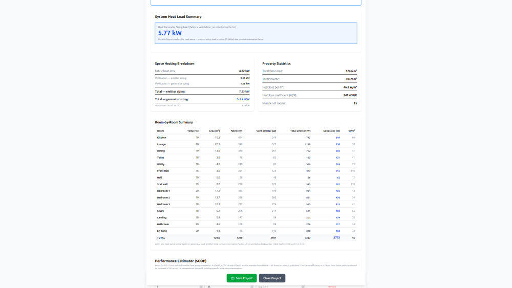
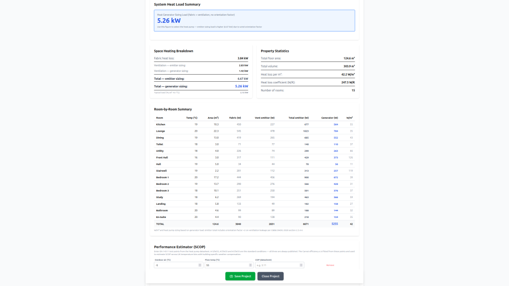
Here you go. This is a lot better. Not quite there yet, but about 1/2 of what you were seeing, but as you can see the calculated fabric losses of 4.22kW are much closer to yours, but this is at -4.6 which is the conservative MCS post code lookup: In the rooms editor, there is a column labelled Design dt (C). When you add a new element, it default to the Design dT of room temp - outdoor design temp. Then next to it is another column for ref dT which is the default delta T between room temp and Typical Outdoor temp. For all internal elements this needs to be set to the difference between internal rooms, or 0 if there is none. I've just gone and updated all your internal settings to this, which has made the difference. I may have incorrectly amended some of your insulated ceiling which may be external? I've then gone and change the outdoor design temp from -4.6 to -2.5 and as you can see, the fabric loss is now down to 3.84kW and generator sizing is 5.26kW: The total emitter sizing is quite large compared to what you're experiencing with your low flow temps etc. which means I need to dig into the calculations to make sure I haven't got something wrong in there, but I suspect that because of the way it has been implemented, there's been a cautious approach taken by CIBSE in how they've implemented the new method. It wouldn't surprise me and is actually a good thing as it's better to upsize rads for worst case scenarion and reap the benefits of lower flow temps over the long term. But I will need to check. I'd also recommend you go over your element inputs just to check the assignment of U-values from your U-value library and some didn't quite match. Hope that helps?
-
14.83kW emitter sizing load? That seems massive. Something doesn't seem right there. Do want to show some of the room inputs? Or PM me screenshots?
-
No, not stupid at all, just something you need to get your head round for heat loss calcs. In the 2 story: - Ground floor gets 1 x Ground Floor (Slab) or (Suspended) + Ceiling - 1st Floor get 1 x Floor + Ceiling You're not really double counting because if both rooms have the same design internal temp, the Design dT is set to zero on both the ceiling of ground floor and floor of 1st floor so there are no losses between them. If there is a difference in internal temp, you just need to keep in mind that the Design dT becomes either + or - the difference. So if one room is 21C and the other 18C, it's +/-3 either way on floor & ceiling. You'll not know this now because the standard U-values aren't in the global database yet, but one thing to keep in mind is that the floor always has a lower U-value than the Ceiling for the same buildup - The CIBSE standard for plasterboard, joists, floorboards, with 100mm insulation is 0.32 I think. The same buildup as a floor is 0.25. Hope that clarifies it?
-
Shrinkflation and filling gaps in plasterboard
SimonD replied to SimonD's topic in Plastering & Rendering
Clearly, I've never measured them properly to begin with 🙄 My assumption was that as with timber products which is what I'm more used to working with, or pipes, you get what's specified. And maybe it explains why I had to get rid of the plasterer I was using? I was just told that gaps above 3mm must be prefilled, nothing about leaving a gap when boarding but he and another did most of the boarding so far. Oh dear! -
I've just plaster boarded up a ceiling and while doing so realised that plasterboard sheets seem to have shrunk? First I thought it was either me or my tape measure and then I twigged the sheets are all actual 2395mm and not 2400 long - my mistake was not taking this missing 5mm into account when I cut short ends of the plasterboard. So rather than waste a load of sheets, I now have some very annoying gaps in my ceiling. Main question is: what should I fill these gaps with? Drywall join filler or some expanding foam? My sense is drywall filler is more sensible. The other thing I also realised is that all my sheets are 3mm less than 1200mm some along both the walls and ceilings the screws get closer and close the batten/stud edge. Is this sheet dimension new or have I just been blind to it before?
-
Windows or Linux machine? I'll test on my windows 11 machine to see if I can replicate. And put it in the bug list for further investigation.
-
32.6/66.2 (although you can just use room internal measurements) = 0.492
-
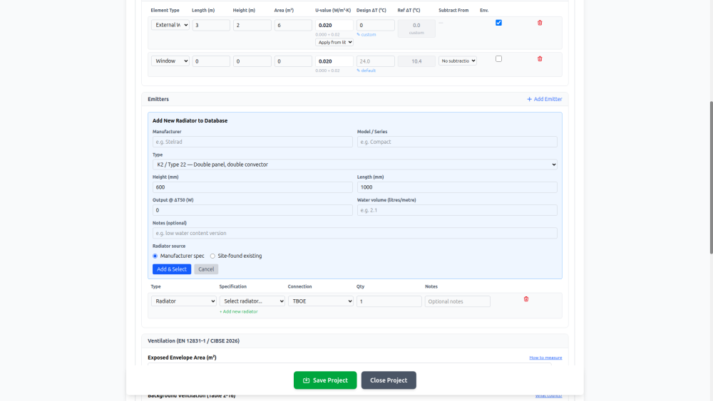
Hmm interesting. The card you should be seeing looks like this: I wonder whether you have the older version of the app from before I sorted the radiator saving issue locally. Can you close your browser and/or do a hard refresh? On both my browsers - Chromium and Firefox, decimal entry in the form I have is fine from keyboard. and I have the add & select button rather than add to database. Would be interesting to see what you get following full refresh. Ah, no sorry! You're in the Radiator Library editor on the multi project beta! So the card is correct. Inputs on both my browsers work fine for decimals on water content. What browser are you using?
-
Yes, of course, share the numbers.
-
Best thing to do with odd shaped rooms, it just calculate the P/A ratio yourself and enter it into the calculator. In the Floor Dimensions and Exposure Card, select Manual P/A, then measure the length of the exposed perimeter of the room and divide by the total floor area - then you can just add the p/a ratio into the Enter P/A Ratio Directly - this is specifically designed for complex shapes. You can the ignore all the other dimension inputs in that card. Hope that makes sense?




