


Gus Potter
-
Posts
2339 -
Joined
-
Last visited
-
Days Won
29
Everything posted by Gus Potter
-
When designing raft slabs and screeds I set a level and flatness tolerance so this should not happen. It can add to the initial price but at the end of the day someone has to do it. Remedial works always cost more than getting it right first time.
-
Welcome to BH by the way Deborah. That is glowing report. Agree. But there is always an inherant risk about buying from abroad. If things start to go wrong then there may not be a local resource you can call up to fix things on site in the heat of battle... like phone a friend. If you are on a tight programme then it's a balancing excercise.. do we go local or not.
-
You have my sympathy and I feel for you. All the best. Once you get it all sorted out, if you feel able, post about how you concluded as it would be helpfull to BH folk to read about your unfortunate experience.
-
Structural warranty company dilemma
Gus Potter replied to Amateur bob's topic in New House & Structural Warranties
Hello Bob. I was rooting for you and hoping you had got this sorted. For all this may be of interest as it lets you see under the bonnet in some respects. Here is how I might be able to chip in. My PI insurance allows me to act as a PD. Now you'll appreciate that I need to excercise reasonable skill and care.. a condition of my insurance. This might work for work for you? The objective as I see it would be for us to work together. 1/ I would review all the design information. I would then generate a list of items I think are key elements and areas of the design that pose a risk if they get changed on site. Could be structural, could be say weathering details etc. This is part of what a PD does. We check to see what changes have been made / proposed and if they impact on the building; either in terms of health and safety risk (during and post construction) or say Sturctural / Architectural deisgn risk. 2/ You would then provide me with evidence that the works to date have been carried out in strict accordance with the design. Now it needs to be real evidence.. not a whitewash as I can't then say I have excercised reasonable skill and care. 3/ Nine times out of ten I'll find a non complance. Now a non compliance is not a bad mark.. the design often eveloves on site and in the heat of battle. What we need to show is that any design changes are still ok. Say it is structural. The easy way is for me to phone up Harely Haddow (with you authorisation) , explain my involvement and have a chat with them. If it's say an Architectural detail or an insulation thing say then we will put our heads together to show that the design change is still ok. 4/ I would then write an evidence based report to say.. I have reviewed the design information and have concluded, based on the information that has been provided to me and after reasonable enquiry that the house has been constructed in compliance with the design. I would then say.. if the design has deviated.. he is what we have changed and here is the evidence / say calculations / drawing details to show that all is still ok. This lets Protek see we are being sensible. My fees: The big risk for me is that I'm coming late to this. It sounds innocuous, acting as a PD.. but it's not.. ProteK are laying off their the risk. They will no doubt ask for a copy of my PI insurance... which will probably be plenty enough to cover your house and they know they can make hay with that if something goes wrong later. As a ball park. Say it takes us four days to sort this out. My rough rate is £300.00 a day give or take. Site visits would be extra. Much will depend on the evidence you have at hand and how much time you are yourself are able to spend giving me the information I need and discussing how we progress this on the phone say. If you want to follow up then PM me. I'm away on holiday soon so may not be able to respond in depth intitially. On the other hand have you considered just writing off the Protek fee? If you are going to hang on to the house for a while then maybe just cut your losses? -
@Saul. So lets say they have made a complete bollocks of this and the houses need to come down. I have had a case like this. You need to discuss this with your legal team, hopefully your specialist Lawyer has already had this discussion with you? Explore the options that might be available to you compensation wise and how you costs and lost opprotrunity are going to be covered. Also plan for the builder going bust? It happens. Do you know how big they are, are there problems on other sites?
-
Starting a business helping Self-Builders, advice?
Gus Potter replied to LDNRennovation's topic in Surveyors & Architects
It can be done but it is a long journey. For me I was a local Scottish Borders Building contractor for the first 15- 20 years of my carear (I'm paraphrasing) have done a self build, like a real one.. doing 99% of the work myself. I reinvented myself at the age of 40 by going to Uni. I'm now an SE and Architectural designer with my own consultancy for about the last 6 - 7 years. But to get there I had to spend about 6 years training after uni.. to become competent and learn how this side of the design business work. How you set out a design brief.. how you get paid and when. How you build relationships to get repeat work from Clients who pay promptly.. which will pay the bills. On the face of it even now (6-7 years later) I don't earn what I could if I went to be a wage slave at an SE consultancy ( I don't get holiday or sick pay but they have you working 60 -70 hours a week once you get to director level). But my quality of life is much better. I have my bread and butter work locally that pays the bills.. extensions, loft conversions and knocking holes in walls. I do quite a few jobs in England.. but these are only the ones that interest me. I like raft slabs and converting agricultural buildings to homes for example. I have other sidelines.. I do some steel detailing for an Aberdeen fabricator and so on. I take on whacky renovations.. lime mortar and old stone. @LDNRennovation I think you can do it.. but to do so at the beginning you'll have to take on anything that crops up.. you'll probably earn less in the first five years but at the end of the day if you put your back into it it will be worth it. -
What will remove this paint?
Gus Potter replied to ennogs's topic in General Self Build & DIY Discussion
Often the case.. but will it be safe? -
What will remove this paint?
Gus Potter replied to ennogs's topic in General Self Build & DIY Discussion
It's a good idea and can work.. but always check with an SE before you do this as the effective depth and end restraint conditions of the trades can change massively and make things unsafe. -
Ha! Save your money folks. I'm balding, a bit deaf, glasses.. long list of latent defects. That said would still like to attend if possible, if not this time then maybe the next.
-
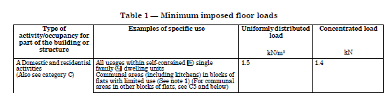
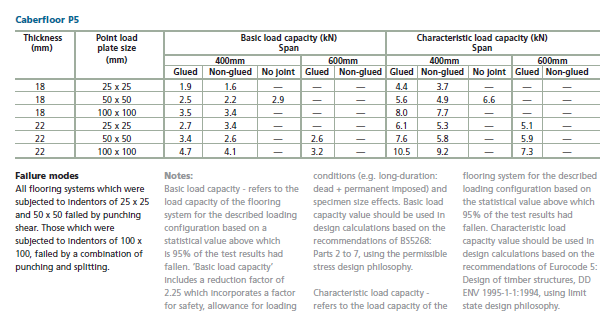
Hello @richo106. Good question. This bath thing crops up on BH from time to time. For a bit of fun I've had a go below to explain in broad terms.. how to have a bathtime without ending up in the sitting room say below. Bit of techy stuff first. I'm going to use loads that don't have an apparent factor of safety explicitly shown as the values I present are based on what is called "permissible" or "safe working loads" that have the factors of safety built in but hidden. I'm also going to refer to the British standards (very much still in use) rather than the Eurocodes... which are not bathtime reading. Let's start with the loads that a domestic floor often is required to carry. BS 6399 part 1 on says: Ok the 1.5 kN/m^2 (about 150 kg per square metre of floor) uniformly distributed load is often seen when you look up any basic joist manufacture's data tables and suppliers of chipboard flooring. But what you rarely see is how much point load say 22mm thick P5 flooring can carry. We want to know this to ensure your bath legs don't punch through the floor in the first instance. The table above requires that the floor can carry a point load of 1.4 kN (about 140 kg). Now say you have a penchant for cowboy boots or high heal shoes. This is a concentrated load which causes punching shear (like bath legs) and we can, if we have the will to live, work this out mathematically to some extent but this would give a very conservative result. For design purposes we want to look at test data. But to make things a bit easier (broadly speaking) we could find some manufacture's data that tells us what the safe working punching shear capacity of chipboard flooring is! Now as luck would have it Caberfloor have a nifty table as below: Start at the top left of the table. For an 18mm thick flooring loaded with a 25 x 25mm contact area the floor can carry 1.9 kN (~190 kg) on glued on joists spaced at 400mm apart... but this is away from the floor edges which are much weaker. This is true but for the doom merchants (if heard of this) if you are daft enough to fill the bath up to the overflow and then step into it when you are still standing you don't displace that much water. That is when it will fail. Motto is.. keep your pants on until fully submerged to avoid embarresment. For me I would be inclined (if the bath is heavy) to take other posters advice and add a few noggings under the bath leg positions. If tiling with large format tiles I would be double up the joists under the bath leg area to avoid differential deflection that could crack the tiles. Also if the bath leaks a bit then the performance of the flooring drops off dramatically so having some solid timber under the legs of a heavy bath is a good idea.
-
This meet up thing is good, would like to participate. I've met a few BH folk in person... but not that many. It's a bit of a journey for me as coming from Scotland. I would try and tie it in with a holiday break.
-
Rebar suppliers that can do 90mm h10 links?
Gus Potter replied to WannabeBob's topic in General Structural Issues
Good, just make sure that you can vibrate the concrete ok and get the pour sequencing right. Go back and just check the design with you SE, in case there is an annotation error.. it happens. -
Fair enough if you take the slab in isolation.. but often these things require a holistic approach. As a designer folk often ask me.. why is your raft slab thicker.. I've seen some slabs at 100mm thick internally.. and I say because that little extra thickness allows me to shed load into it which makes the other parts of your design cheeper. Why have you got the extra complexity in my attic conversion.. often because it lets you get the stair to fit and complies with BC regs We are renovating a historic building so we can't apply standard rules and need to design from first principles this is the way to go I say.
-
Post your design drawings if you want and see if folk on BH can put some reasonable cost numbers / suggestions to this. In terms of pricing raft slabs ideally we want to split out any excavation and back filling cost from the slab and then further split out the insulation cost.
-
Structural warranty company dilemma
Gus Potter replied to Amateur bob's topic in New House & Structural Warranties
Hello Bob. I've not been tracking this thread much and have been busy with the day job. I'm assuming you are in Scotland? A few comments as best I can which may relate to your build. I've made a few assumptions, correct me if I'm wrong. To get your building warrant I think you got your pal to do the drawings (call these the Architectural Drawings) and for the structural design you went the SER route and got an SER certificate from an SE? As an aside there is another route which I use and that is to submit structural calculations to BC who then get their in house Engineers to check. It's not true that you must have an SER registered Engineer to do self builds in Scotland. Either way the process in Scotland is much more rigerous than often in England and the warranty providers often do not recognise this.. particularly if you have a case handler that knows little about the diffrent ways the Scottish system works. What can often work is to educate and lead them through the process.. you can instill confidence that you know what you are doing. The warranty folk are trying to do is to limit the worst of their exposure. After a while on Buildhub you get to see the folk who want to do things properly and at the other end there are those that cut every corner under the sun and bend the rules. Now Protek call you up and ask if there is a Principle Designer. Under my PI cover I have an element that allows me to act as PD, but always within the limit of my compentence. My insurers ask what experience I have and to wrap the PD bit up they say ok.. Gus we will cover you so long as you excercise reasonable skill and care. If you run about and do daft things we will not pick up the tab. Now the same ethos applies all the way down the food chain to the self builder. But the remit of a PD does not extend to ensuring what is shown on the drawings is actually built properly on site! Now @Amateur bob the same rules apply to you and you can use them in principle I think to solve the problem you have. 1/ You have a building warrant. 2/ You have a structural design. 3/ You need to be able to demonstrate that you have built everything in accordance with the drawings. How do you do that in Scotland? Well when you get a building warrant in Scotland there is a bit called the Construction Notification Plan (CNNP). This means that you have to notify BC where you are at and they often come out to inspect. @Kelvin may be able to offer some help here as will @saveasteading. If you educate your insurance case handler on the Scottish process then that may be enough to get you over the line. You can also add loads of photos to show you are being dilligent and following the design drawings, employing where you can competent builders and so on. To get a completion certificate in Scotland you often need,if going down the SER route, a thing called a form Q. You can get the warrant to start the work but the SER Engineer needs to see all the design calcs from everyone that has a hand in the design. A good example is calculations for roof trusses which are not available at the start of the job. If all this info is not forthcoming at the end of the job and gets the SER approval then no completion certificate from BC... and then you are totally stuffed. This is where I gain an advantage over the SER route in that I'm doing all the calculation work up front most of the time. @Amateur bobOn no account offer up the below until push comes to absolute shove! as it will cost you money. I think you can navigate this ok without getting into a bind. You are not the first Scottish selfbuilder that has encountered this issue so take heart from that. But say that does not work and it goes nuclear! One option is.. You could call me for example. I would intially ask for all the design information and site photographs, spend say a day reviewing that. I would then come to site and look about.. ask you to walk me through how you have got to where you are, listen lots and then ask you lots of questions! I would then provide a evidence based report on what I have observed and whether what I have visually seen complies with the design drawings. This would be based on my 20 years experience as a building contractor / my 20 years design experience and all that gets backed up with my PI cover. Now say I find something that is not in compliance with the drawings? Will BC see this also, maybe, but at the end of the day you want a safe house. I'll have a look at any non compliance and see if what you have done is still ok in my view.. say it is a structural thing. Now to get your completion certificate under the Scottish regs the BC officer may say.. hey you have deviated from the SER design certificate and it's now invalid. What I do is to work out if it still is ok, maybe do a drawing or two and some calcs, phone up the SER Engineer, have a chat and resolve any issues. The same rules apply if say you have deviated in term of DPC, weathering details and insulation details.. call this Architectural things. Bob. There is a fee attached to this and I would be looking at what you signed up for and see if you can get your premium back and go with a different insurer. For all on BH. As an SE I carry professional indemnity insurance. My insurer's look at my experience and competancy. The fine print says ok.. Gus we will insure you provided you don't take on designs that are outwith your competency or try and manipulate the terms and conditions of you insurance contract.. in other words.. don't be an idiot and expect us to pick up the tab. What they absolutely do is to insure me if I make a genuine mistake or get pelted by other folk that have made mistakes and try and pin the blame on me.. which is quite common in the construction industry. @Amateur bob This could be a way of solving your problem at the extreme end, try and avoid by educating Protek. -
Rebar suppliers that can do 90mm h10 links?
Gus Potter replied to WannabeBob's topic in General Structural Issues
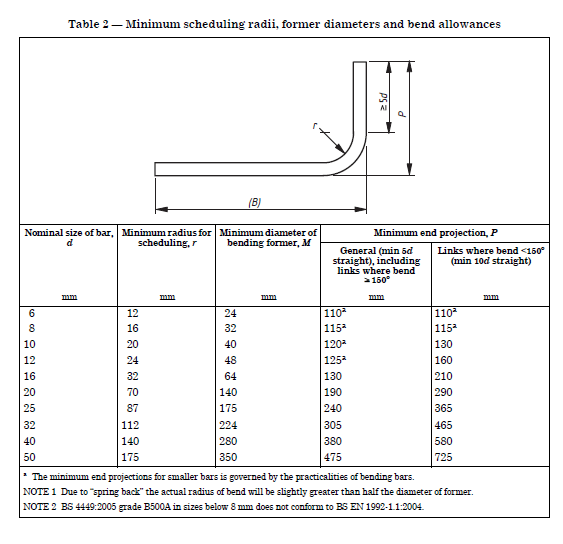
Shape code 51 is this Table 2 says this And there lies your problem. I suspect your SE has made a bollocks of this link / beam design. 10mm links with only B = 90 mm? even if in terms of buildability and cost.
-
I'm cack handed, good at the maths but not good at spelling and grammer. I'm going to try and distill but add a bit to my last (long and admittably long rambling post with less ramble).. Seriously folks. @Saul.. you buy a house in good faith, you see something that worries you, do some research and kind of know you are right.. then you get fobbed off, you get over that and then you encounter the delay, deny and defend tactic. This is standard industry procedure. Now as I've said I do a bit of claims work 95% probono . I've represented Architect's that have got sued and domestic clients.. I've only been in court once and won hands down! It's not that I'm a fair weather SE it's because I know how to approach a problem and "change the conversation" if need be. Also, If you ask me to fight on you behalf and think you are swinging the lead.. I'll turn your brief down. The pragmatic objective is to not go to court but get a good settlement. In @Saul case the opponents have much to lose. If they don't settle then their insurance premiums will go though the roof, they could end up featuring in the daily mail or getting a black mark from the HSE. Now even if there are a few houses with the same problem then in the grand scheme of things it's not a big financial problem for say the NHBC.. they have huge resources and "lay off" in the insurance market for example. It sounds brutal but that is how the industry works. @SaulYou must absolutely must get your head around this for your own sanity. Now what about @Saul issue. This will be dealt with at maybe middle management level. One of the secrets is to make it easy for them to just pay out. Everyone has a boss. What you seek to to is to find a few things that are very difficult to contradict. Often you see folks in dispute about cracks in the walls. But that may or may not be structurally unsafe.. the insurer / builder will say " general shrinkage" we told you that in the fine print when you bought the house. As an SE it is very hard for me to argue this case as it's subjective. The Eurocodes make it even harder to argue this case which we call serviceability.. the Eurocodes almost allow the builders to pick their own crack and shrinkage widths.. as an SE I'm often on a hiding to nothing trying to argue this as the NHBC et all chuck professor x and y at me. But as soon as I talk (in an evidenced based way) about the strength of say beams and how they rely on not having too much movement of the walls the Professors point to their fine print and back off! At that point the game is nearly over. I don't discredit the Profs reports I just point out their limitations and how they are invalid to the context of the arguement... by simply asking a few targeted questions. Also I find that some same Professors have had a hand in writing the design codes.. where they stress the importance of say beam bearings, wall ties and building stability systems. @Saul may have been povided with a report.. but you need to know enough to know what it says and means.. but basically look at who paid for it! To understand the meaning you need someone like me! There is no way on this good earth that a laywer will know this.. unless they have a dual qualification.. laywer and SE! Now again @Saul says there is a report that ok's to have a weak mortar. I'll bet that said report is highly qualified. Yes, it may be written by an expert, I'm not challenging that.. what I'm saying is you need to look at everything else that relies on the mortar being of sufficient strength and durability in terms of fire and damp proof protection. You can get this information by phoning up the manufactures. and talking to their experts. At the end of the day they can be quite helpfull. They don't want their name tarnished either! Just imaginge the daily mail saying.. 40 houses need to come down because of wall ties.. when in fact it was shite mortar! Summary : My own view on what I have read on BH is that @saul has a good case.. but to get the best out of it Saul needs to control and lead the laywer.. if not then the case could be potentailly lost or pay badly, the house blighted., and the personal stress and damage to health is just not worth it. I've had a case where the developer has just bought the house back, paid a healthy compensation and you need to sign an NDA. @Saul don't rule this out as an option. I made this work by pelting them so heavily on the cost of HSE compliance, structural safety that a deal was done. The Client wanted an element of "punishment" for what the developer had put them through. That came as part of the deal.
-
Taking people to the small claims court
Gus Potter replied to Alan Ambrose's topic in Party Wall & Property Legal Issues
All good stuff Alan. For me as an SE and the thing that keeps me awake at night is the thought of designing something that falls down and hurts or kills folk. If I did that then there are many examples of SE's that never work again. Persoanlly I would find it a hard thing to live with, I hope it never happens. I've seen fatalities on site. In that context sometime I see folk on BH doing stupid things structurally or things that I can see are going to cause problems with say BC compliance. But this is social media and you all wear big boy pants. Good advice. -
This is pragmatism and actually very clever.
-
Hello Saul Sorry to hear you are having a hard time. Here are a few comments. They are just general but may help you, even if just to rule out. Often ruling things out let's you focus. I do a bit of Claims work now and again, not a lot as I would rather be having fun designing stuff. I'm off the day job so excuse the spelling, grammer and hope you get the jist of my comments! When you get sight of a professional report you must read the caveats and scope of the brief. But as a lay person you will still struggle to understand what these actually mean. This type of report is carefully crafted. You have a lot riding on this and so do the insurers etc. Ok I see you have gone a bit legal.. part of the torture these folk put you through. I was interested when you discussed about the diffferent views on the mortar compressive strength. There was professional who: Now that is almost / true in some context.. An example. Say you have a building that is made out of quality Bath Limestone. The beds are just there to keep the weather out and allow the stone to move so we don't get movement cracks...and shed some of the local stress in the stone. Anyway.. You are in dispute, your text and posts exhibit an often observed pattern from my end. You may be feeling that you are getting stuck as you are focusing on the mortar. Now there are lawyers and so on thta add to the confusion. I often feel this is a standard appoarch by say Contractors / Insurers. From their end it's about numbers, size and frequency of claims. Let me paint you a picture: Let's say you find an SE that is a crusty bugger and who does everything based on evidence, knows how the game is played. Let's also say that this SE knows how to inform your Lawyer, who may be young and wants to learn / win and pocket a bit of cash. For me as an SE part of my claims work is to provide the tools to allow the laywer to fight the case. I always go back to basic design principles and most laywers can make hay with that. You write to your opponent and ask to see the original design calculations for the house and if there are any "as built drawings" Now 99% of the time these will not be provided. No calcs / drawings you now have opened the door! Saul you are focusing on mortar strength, say durability, a professional report is introduced about 1:10.5 mortar mix. Your opposition is tying you in knots, taking up your time, causing you stress, potentially blighting the value of your house. This is standard fair and practice when you go up against developers and say the NHBC.. especially when there may be more than one house at risk. What can you do: Ok you are feeling that you are fighting a big wall. BUT it's an old expression.. just change the conversation!.. it's an old addage from I think 1960's marketing.. but still true to this day! Go around the wall! I do claims work now and again.. I don't take on a Claim unless I think I have a decent chance of winning. The NHBC et all have huge resources.. the trick is to find a way round their firewall. I focus on structural safety / fire safety and how all the other ements of the building rely or not on the wall and mortare for example. You can quickly turn the tables on them and rack up their costs! Importantly you can highlight structural safety issues which puts the shiters up them. They have to address this quick as you might report them to the HSE. You are concerend about say the mortar falling out over time.. I'm concerned as an SE about the current structural safety! To fix this the NHBC often need to fix the structural safety aspect which fixes the thing we started argueing about in the first place which is the mortar strength..there are different ways to skin a cat! Well as a home owner you can write, I'm just touching on a few examples here.. but in my day job I go to town! I'll go into any beam bearings on soft mortar, durability.. the whole lot. Once I get going with my SE design safety hat on it can be free for all. In my experience most insurers just throw in the towel.. but you must educate your Lawyer and a good SE for example will do that. Some question you may ask as a lay person: 1/ I know the roof sits on the walls and puts vertical load on the walls does this report (1:10 etc) take the behavoir i=of the buildingninto account. I would love to see copy of said report for interest. 2/ I know the wind blows on the roof and to stop it moving sideways or upwards it needs to be tied to the walls. I know that the regs require the masonry to be of a certain standard so the vertical and as equally important the sideways wind loads are transferred to the walls all the way down to the foundations. 3/ The floors tie into the walls and for these to work the walls need to comply with the assumptions in the floor design. 4/ The wall ties as recommended rely on a certain strength of mortar bed.. if my mortar is not strong enough then that invalidates the wall tie design. 5/ Fire protection. Now I can see the mortar is falling out on the outside. If it is happening on the inside then the fire pretection in the cavity may be compromised? How do you know it's not? 6/ Bridging of DPC's and wall ties in the cavity.. is the mortar falling out causing bridging? 7/ I have windows and doors.. my supplier needs to verify that the walls they are fixing into to comply with the standards. I've just touched in laymans terms on some questions you may want to ask. Gus (that's me) What I do from time to time is to phone up the technical department of say the wall tie manufacturer and say I'm in a bit of a bind what do you think unoffically ? Is this defensable or do you think I'm right? Remember folks that from time to time I may defend a builder? To close: To win this I think you need to change the conversation.. focus on structural safety and how the weak mortar has invalidated the rest of the design. Try and rack up the cost and time to defend for your opponent. At some point they will come to the table and want to negotiate. That is a story for another day.
-
Fire protection of steels
Gus Potter replied to Post and beam's topic in General Self Build & DIY Discussion
I agree with you. there are a lot of conspiricy theories.. but I'm inclined towards looking at what I know. The fire protection got blasted off the steel.. it got hot, failed, which cuased the building to collapse. The planes impacted on more than one floor. Where the plane hit was at the height where there was a lot of dead load from above. Once that dead load started moving the dynamic effects were multiplied. You only need to lose say 1.0 or 2.0 metres of column fire protection over a number of columns to promote what we call disproportionate collapse. I still find it personally uncomfortable to distill and write about it in this way when so many people lost their lives. No is a hotpoint and looks good! I'm in awe of the Space X Engineering team. Stainless steel is a wonderfull material.. it's ductile, forgiving but comes at a cost. I love what Space X is doing.. they have the best Engineers.. we British used to be like that! For me it's about how the marry up the best young talent with old school testing engineers. -
xxx for you! Yes you are right.. I can't think of a time when you have been wrong! wish I could., just kidding. For low rise domestic design we try and limit the SE fee. At foundation formation level (the depth of the hole we dig) we dig a bit of soil out and put some concrete back in. But then we often make the founds wider for buildability and call it a day. Good point. We as SE's have a term called load sharing and load spread..,. similar to electrical diversity when sizing a supply or consumer unit. The piano and Eltons "charisma" gets spread about by the time it reaches the founds. While we do calculations some of these are based on a best guess and experience. The soil under the founds is variaible , best guess. If we are blessed with say 4 Eltons on a floor then that is where the safety factors come in. Anyway Elton does not stay more than a few hours which will not impact on the long term settlement.
-
This is a good point. On normal low rise houses we may go to site and dig a few trial pits and find CLAY soil. We can do some tests on the soil (or just look at and mould it in our hand) and based on that information we can calculate how much load we can put on the soil before it fails, like just totally gives up the ghost big time. We don't want that to happen so we may say let's put a factor of safety of 2.0 on that. An example would be.. say we calculate that we can put thirty tonnes (about 300 kilo Newtons kN) per square metre on the ground before it totally fails. Puttinga factor of safety on that of 2.0 and that gives us a number of say 15 tonnes a square metre. But CLAY soils settle over time. The next calculation is for settlement. In the UK for normal low rise housing we often limit this to 25mm over 50 years. This gives us another load that the ground can carry without settling excessively. We pick the lower of the two numbers.. and often you'll see on you SE drawings what is referred to as say.. "this design is based on an allowable soil bearing capacity of 100 - 150 kN/m squared which is about 10-15 tonnes. When we have a SAND soil ( I capitalise as the use of upper case denotes the dominant component of the soil) we carry out a similar calculation but are very keen to know about the level of the ground water and where it might be in the future as this can half the strength of a SAND soil. Ben. The biggest number on your drawings is 12.5 /5.0 unfactored load. Now take that as is and add the dead (the weight of things) and live load (people, snow, roof access and so on) together which give 12.5 + 5.0 = 17.5 kN per metre run of wall. Now say that sits on a simple strip concrete foundation with a bit of A142 mesh to stop it cracking too much. Also say that your soil can carry an allowable bearing pressure of 100 kN per metre squared. Let's see how wide the foundation needs to be to carry that load. 17.5 kN per metre run / 100 kN/ m squared capacity= 175mm! But that is the theory.. Incedentally if any of you have renovated old Victorian houses you may find internal walls that are just sitting on bricks laid sideways on a bed of lime mortar on the soil. So while the number above look crazy it's not actually in old money. Anyway back to your build Ben. You can't reasonably dig or fit a wall onto a found that narrow. When we go to set things out for a DIY self build found.. we may be not get the marking that straight. If your builder / you get a local hire JCB they often pitch up on site with a 600mm and 450mm wide bucket and a blade bucket for scraping the ground and tidying things up.. Thus on a house like yours I would say can we just do the narrower internal wall founds with the 450 bucket, the external walls with a 600 bucket. Make all the foundations 200 mm thick. Alan is spot on, this happens! In the UK we still use a combination of the British Standards and the Eurocodes. These codes have different factors of safety and we combine the loads in different ways depending on which code we are designing to. By providing the unfactored loads we allow the different suppliers / package designer more scope. That drives down cost.
-
Fire protection of steels
Gus Potter replied to Post and beam's topic in General Self Build & DIY Discussion
Good point, as aways. Steel is an elastic material, like all materials. In the UK we don't suffer from particularly low temperatures, but in some cases where we have structural steelwork that is exposed to low temperatures we select a steel grade that is more ductile (less brittle). Going in the other direction when we heat it up it starts loosing "strength" that give designers concern at just over 300 deg C. @saveasteading is correct about the oven There is some softening of the steel at 250 deg but it is for all intents negligeable. . Below is a typical fire curve for steel from the SCI. Simplistically when we design steel for fire we may pick the 550 degree curve. Work out the loads on the building during a fire. When we do this we don't assume the building is fully loaded in the same way as when we are designing for day to day use. Fire is what we call an accidental load case and we reduce the factors of safety and the loads to reflect that this is an accident. If we did not do this then building cost would often be prohibitive. Fire protection is about providing a protective layer of material that insulates the steel in one way or another. Or for example you can use say sprinkler systems that reduce the heat and duration of a fire. Fire is a terrible thing. What we aim to do is to provide warning of a fire first. Smoke and heat alarms say and this lets people exit the building. We aim to provide them a safe route to do so. Here we may see reference in the regs to escape windows and the like on a single story house, we avoid having a room off a room with no escape window for example. On a three storey house we often want to have a protected stairwell or a sprinkler system with an enhance fire detection system. Once buildings get taller (often 3 habitable floors or more for domestic use) we need to think even more about people that may be trapped. Here we want to further protect the floors, walls, the structure and so on to provide a safe shelter space until the fire brigade can effect a rescue. During and after the rescue we need to protect the structure so it does not collapse on the fire brigade or set light to any surrounding buildings.. and that is where the other structural aspect of fire design comes into play. Often if your house is well away from other buildings the fire brigade (if sure no one is left inside) will fight the fire from a safe distance.. or if in doubt just let it burn. I take Nick's point.. but at the end of the day it's often the insurer that has to pick up the tab. The more you can limit the extent of the fire damage the less they often need to underwrite and that is reflected in the premium.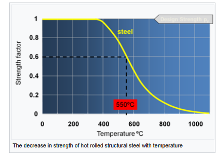
-
Fire protection of steels
Gus Potter replied to Post and beam's topic in General Self Build & DIY Discussion
Yes I agree. In simplistic terms there is chemically "locked in water" in the plaster board. The heat transfer is slowed as the plasterboard "soaks up the heat" as it is forced to change chemically. But.. often the fixings are the vulnerable point. An easy way of getting your head round this is to go to the BC standards. They talk about fire "resistance" and fire "integrity" The resistance bit is to do with a material transferring heat. The integrity is about making sure that the fixings and the things the fixings go into remain ok.. as if they fail then boards say fail also. The regs combine intergrity with resistance to give you the overall number. In summary though. Say you are completely new to this. I would explain that steel starts to lose its strength when it gets hot.. that can start at temperatures similar to when your oven is at full whack.. say 250C.. this lets the home owner get a feel for what we are talking about in terms of how quickly steel can loose strength when it gets hot. What we need to do is insulate it so it does not get hot. Then we look at the different ways of doing this. @saveasteading and others have pointed out the different ways we can go about keeping the steel cool.

