Gus Potter
-
Posts
2339 -
Joined
-
Last visited
-
Days Won
29
Everything posted by Gus Potter
-
This New York skyscraper had a 1-in-16 chance of collapse.
Gus Potter replied to Alan Ambrose's topic in Research Resources
It depends.. but for all self builders out there. Often in my sometime lengthy submission to BH (this is kind of one of them) I refer to the Bristish Standards as they are often easier to understand and still applicable particularly to self building. But in this case to get a handle on things we are better to look to the Euro codes as they expose more of this factor of safety malarky cf some of the Bristish standards which work on permissible stress, not that many mind, but enough.. all the safety factors get lumped together. Let's take a steel portal frame first. This could be an agricultural barn conversion. Most design codes recognise that many are put up out of plumb, the steels are not straight due to the hot rolling process. If you have seen steel erectors work, they have a sledge hammer in the van, they use drift pins, crow bars, the tele handler (when no one is looking) and straps to pull things into place to get the connection holes to line up for example. When it comes to levelling base plates, you maybe need to go and have a tea break if you are a Client / Engineer. To help us get round this we assume that the frame is erected out of plumb by 5.0 mm for every meter height. 5.0mm / 1000mm is 0.5% gradient. This means that on a 6.0m high steel portal the roof could be sitting off centre from the base plate by 6.0 x 5.0 = 30mm. We then calculate this eccentric load and apply as SE's in our design, this is what we call a notional horizontal load, which is basically a saftey factor on workmanship and manufacturing. You'll also find this figure in the British Constructional Steel Association guide to Steel erection which describes an acceptable level of workmanship that can be reasonably expected on site. Ok turning now to timber design. Typical thing you see on BH is folk using joist hangers and angle brackets. If you take say a Simpson Strong ABR 9020 bracket. Here they declare the Charachteristic strength which then gets divided by a material factor of commonly 1.3 to give the design strength, sometimes shown as the design load. Don't mix this up with a safe working load as the loads also need to be factored UP first. There is no workmanship safety factor here. The workmanship is controlled by other bits of the design codes where we make sure the nails have adequate edge / end distances and so on. If the chippie / joiner does not follow the drawings or has not been properly trained there is no fall back position. Masonry.. bricks and blocks. Here again we rely on, as does many other aspects of the build porcess, on the British Standard 8000 series which relate to workmanship and tolerances. But qualitively we could look at the BS 5628 part 1 for a bit of ball park guidance. Below is a screenshot of the masonry table. Normally you see SE's using the bottom right saftey factor of 3.5 as the factor by which we reduce the strength by. So say you are using a 7.0 N dense concrete block in an class (iii) M4 mortar. Characteristic strength is 6.4 N/mm sq. Take the 6.4 / 3.5 = 1.83 N/mm^2 or 6.4 / 2.8 (bottom left figure) = 2.29 N/mm^2. So in terms of construction control you get 2.29 / 1.83 = about a 25 increase in performance. But on a self build you just won't spec this as the reality is that the self builder will never be able to execute this, and to find a brickie that can is whishful thinking, then you have the additional labour cost. In the round then we need to establish a reasonable quality of workmanship. Here we may look to the NHBC guidelines and standards for tolerances on the masonry. In summary your workmanship needs to be to the design codes or manufacturer's recommendations. The manufacturer's need to sell stuff and it's fair for them to assume you can do the work to a reasonable recognised standard.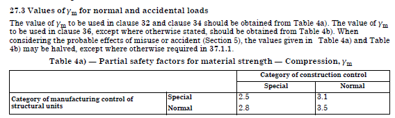

-
On the face of it Nick I would say the welds are concave and not standard. I'm entitled to do this based on the photos, to make reasonable enquiry without being a tosser as best you can. NIck, I'm just saying as an SE that welds look concave and if this was standard SE stuff then it's fair for me to ask as part of my due dilligence to ask is that ok? are the welds heavily loaded? Welds can be pretty strong after all if not subject to bending forces. Now if the loads are low then you can reduce the throat width and the ones you show may be just fine. So yes of course I don't understand the overall context.. but what I'm trying to do in my posts on BH is to give self builders tools and reference documents that they can use to get the best out of things and to provide informationto help them say to a builder.. that looks no good and here is why I think this way. But I'm not going to back off from this. If the weld you show in your picture has been designed on a 6.0. mm leg length which gives you an effective throat width of 4.2 mm and I can clearly see that the weld is concave then it just looks off! Now it may be just fine as the loads will be low, but I'm trying to alert folk on BH about how SE's design normally, to support them when their gut feeling is telling them... that does @Ay8452 not look right to me. The whole connection and what is round about is looks seriously iffy to me as an SE. @Ay8452 banter hat off .. get your SE to check this as built on site for your own safety. You have thermailite or similar block in there be safe and ask questions. Ok banter on BH keeps the ball rolling. So in that spirit.. If we all got on all the time it would be totally boring. In Scotland we say.. "come on ya yadge" I think in Wales you break into song.. xxx
-
Ok I have attached a guide I use as an SE for Weld inspection. For all on BH it's a great document for getting a handle on what might or not be dodgly welding. If you are a self builder then it's a good document that you can refer to if you have worries about welding on or off site. Ask, raise your question with BC if they think the weld is compatible with my attachment. It is highly unlikely that they will know about this stuff and if they have any sense they will say .. I don't know.. if they say it's ok ask.. are you insured to put this in writing.. they won't be! As an SE, Client's ask me some questions that I don't know the answer to. I say I don't know but I'll go and find out! This is the mark of a professional but as a self builder you can read up also and be well able to make sure you are getting value for money out of folk like me that do this as a day job. What I can say is that if it is supposed to be a structural weld then it ain't going to pass. I'm telling you this as me! In fact if you look at the document I've attached you'll find that the welding is so shite it does not qualify as a weld at all! Now if you have a builder that is taking the piss what you have here is on site is welding that I bet will be non compliant with the staturtory HSE law on CE compliance for structural steel, that is you CE compliance (for structural steelwork see internet and the law) So at the end of the day if you builder is taking the piss they can go to jail! You probably hold a lot more cards that you realise at the moment so keep you head up! Don't accept this until you know more. Indeed Nick.. but as as SE the standard throat with is 4.2mm.. for a 6.0 mm weld leg length. The weld you show `looks of good quality.. but I would scrutinise this to make sure is actually has enought beef.. pretty it may be but.. to be blunt the weld in your picture is concave.. it should be convex so straight away I say.. it might look good in the pic but the throat width is not enough on apearance .. unless it is a partial penetration weld. So @Nickfromwales I won't be passing the welds you have shown either based on your photos! Guide to Weld Inspection of Structural Steelwork BCSA Book 54-12.pdf
-
Wall for floating staircase?
Gus Potter replied to flanagaj's topic in General Self Build & DIY Discussion
It's remarkably simple once you understand where the loads go and how the the treads twist (torsion) on these "flying stairs". The secret is in the detailing of the stairs, the SE stuff is straight forward! Often the stair does not need to cost a lot more.. but the time is in the devil of the detail.. making sure that the surrounding structure is designed and built so the thing works. Most folk on BH split stuff up into packages, seek the lowest cost.. so it does not work logistically.. but then you can't afford your "flying staircase" as everyone else has cut off your options.. and you end up with some crap version that probably costs you more anyway. One way is lets say I go and buy a motor bike off the shelf. Then I shop about and but the parts of ebay will cost me more. This is an affliction particular to self builders, but an unavoidable one. You need to know if you can afford to sefl build.. and if you have not done it before then your only way is to go the route of building a bike like by buying parts like a motor bike. This used to work ok as there was plenty money to be made in self building.. but now things are much tighter financially. Look at it this way.. these flying stairs have been built for hundreds of years.. do you think these old builders did this out of charity? For hundreds of years they know how they stay up.. in the last hundred years and a bit we have proved how they do their thing mathematically. The thing is look at how these old builders made their money! and then ask can I make the same savings! If you have a look on the internet and search for flying stairs in torsion you'll see how they work. Technically you can do this with a good thickness of oak tread with some modification and with a good stringer bolted to the masonry wall it will work also. Lastly you can also utilize the ballusters and handrail.. it's a traditional way but if you are enthusiastic then in the round it's massivley elegant as you use every part of the stair both architechturally and structurally. And if you put all that together then you are on you way to having a work of art! It does not need to cost the earth! -
Public liability insurance - nothing else (yet)
Gus Potter replied to Drellingore's topic in Self Build Insurance
Hiya. The film management should be used to sorting this out and I suspect that they will be a deviant (commercially of course) bunch. Look at it this way.. they could be surveyors that are coming to "measure up" and just taking some video with some commentary. If they are not used to building sites.. they are a liability. Now here you may come under more scutiny, do you have a principle designer, are you fully complying with the CDM regs and so on. Make sure you are fully HSE complaint, who is your PD etc? If one of the film crew get hurt (twist their ankle) you will be the first to go under the bus! That said I am rooting for you and looking forward to seeing you on the Telly! -
This New York skyscraper had a 1-in-16 chance of collapse.
Gus Potter replied to Alan Ambrose's topic in Research Resources
It is. When I was at uni I had a lecturer that was about ten years older than my self, I went to uni at 40 he was about 50 and had a long an varied experience first as a Civil Engineer (like @saveasteading) and then got into structures. He used this as a teaching example about how you need as an Engineer to "sense check things". A good Engineer uses a computer, maybe complex analysis (say FE) to refine the design, seek economy.. but we always use the model as a tool. We never take computer output and sign off unless we have sense checked it. That is dangerous. Another example is the Hyatt Hotel collapse. This came about because of; a simple steel detailing error, if the detailer/ engineer had put a big red note on the drawing.. don't (expletive deleted) about! , the contractor did not change things on site ( explain the buildability) all coupled with a loss of engineering oversight and site inspection. https://en.wikipedia.org/wiki/Hyatt_Regency_walkway_collapse Now in terms of self building.. always think before you let your contractor go off and do their own thing! Don't let them sway you.. we have always done it this way and we know best! The modern self build is becoming a lean design animal.. to make it worth while (you make some money) designers are pushing the boundaries and with that comes a need for builders to get with the programme! -
Oh dear, that didn't go well.
Gus Potter replied to Alan Ambrose's topic in General Self Build & DIY Discussion
There will be two sides to this! There are a few folk on BH that have built houses worth more than £3.0M if you include the land value. -
Good response! Often as a designer we seek a happy medium. Somewhere between your good points..
-
Wall for floating staircase?
Gus Potter replied to flanagaj's topic in General Self Build & DIY Discussion
What a lovely proposal. This floats my boat as an SE. I imagine you have seen a "floating" stair in say a tenement (Scotland) or a traditonal town house in Bath. I'll try and explain how these roughly work. Each tread is not a cantllever. It is supported by what can be a thin wall at the inner edge.` Simplisticaly the way we design these is to let the outer side of the tread rest on the one below and to make it work this has to continue all the way down. The treads are actualy, in torsion so where they are built into the wall the wall has to be designed to resist the tread torsion, so you need a good weight of wall above. By default the treads need to have torsional resistance. A traditional stone stair tread has enough beef to satisfy. You find more detail on the theory on the internet. It's not a design job for the faint hearted but most SEs can handle it.. but you'll need a good height of blockwork above (to provide ballast weight) and maybe some engineering brick round about the tread end where they run into the wall to take the local torsional stress. -
Public liability insurance - nothing else (yet)
Gus Potter replied to Drellingore's topic in Self Build Insurance
Ah.. that will change the game a lot! You'll need some new threads, a hair cut and so on if you are going to be on the telly! -
Good question. There is a lot of good technical comment from previous posters. MVHR is well proven technology if you design it right, build in a bit of spare capacity so you can sell the house on without copmpromising the value and live in a certain way. So in that context I'll paint you a diferent picture. Now I am a past self builder, site was in the country, like waaay out in the sticks. But round about me were other young couples that were also that were doing the same. Most wanted a house that was large enough to fill with kids. Most of us were in our 30's or a bit younger (but there was also a cohort of retiring folk who really got behind the ethos and they also wanted chickens and plenty fresh air.. like open windows and doors) and wanted to send their kids to the good local school, get chickens! And sure enough it all happend. Good teachers moved to the local school and it thrived. But it did not stop at chickens! Then there were sheep, goats, more kids, the dads got involved in the local scouts, the local pheasant shoot, (they learnt to shoot as the foxes were eating their chickens) their houses became a hive of activity.. the doors were open and shut from morning to night, the new kids got sick at first when they moved to the country so windows were open / shut .. Take a step back @Wadrian and review again! What function you want your house to perform. You are starting, it seems, to think about a bit of technical design..you'll get loads of info on BH so always review, it's Ok to change your mind as you go and learn more. If it just a house for say two of you that are in eh "later years like balding me" or a mental family with a country feel, you get to smell / topuch what is happening in the outside environment, If mental then MVHR is maybe not the best option in the first place! Personally as a designer, SE, ex building contractor with 40 years experience my personal horror is to live in a sealed box! It looks great on paper but few years down the road it makes no commercial sense to me in the self build market ( it will break down so if you can avoid installing it in the first place? ) and is probably bad for your kids.
-
Mansards with no soffit ovehangs
Gus Potter replied to jackcowdrey's topic in Lofts, Dormers & Loft Conversions
Great comment and input from jackcowdry and Mike. Old roofs were so draughty with traditional sarking / battens that the last thing on the builders mind was to introduce more ventilation. Looking at these more modern photos I'm at a loss how they have ventilated it as the large format slates won't be helping as they are so tight. You could use traditional timber sarking with a 5.0mm gap between the boards and a breathable membrane (Tyvec Supro or similar) but again these modern slates are so tight you need to be careful. Potentially you could get eaves ventilation (50mm air gap up the roof with minimum 25mm width soffit ventilation) up behind the gutter but there is no ventilation at the ridge.. unless it's all hidden on the back side? The potential for damp at the Juliet balcony looks high. A bit spoilt by the plastic soil vent pipe. A nice bit of cast iron pipe would compliment.. if the budget stretched to that. As a rough guess it could work with a smaller slate size, a bit uneven with plenty air gaps between the slates.. but I can't promise at the moment! Food for thought though eh! -
Have a quick chat with your SE. It's often missed at the Architectural design stage.. you get hung up on the thermal bridging, water penetration and so on. But masonry cavity walls can be designed as vertically or two way spanning so they resist the wind load and stay stable (not buckle sideways) when you also load up say the inner leaf with floor joists or the roof which often sits on the inner leaf that load the wall off its centroid. If you put in DPC's wily nilly you can break the vertical spanning capability of the wall which in this case it look like you might have done. You have no wall ties at lower level so that looks a bit off so this is related to the above as you have a quasi rocker bearing in the wall. I've not spent long thinking about this but I would first look at, and then test my arguement: 1/ Delete the cavity tray that runs from the bottom of the cassette vent back up into the inner leaf. What is it doing when you have vulnerable insulation below it anyway? So now we have done something good structurally too! 2/ The DPC on the inner leaf is shown at top of screed level. I would look to drop that to bottom of screed (think buildability) level and then turn it down behind the insulation against the inner leaf and stop it 20mm short of the cavity lean mix fill to stop any potential wicking effect. 3/ Get another wall tie in below the lowest one you have shown to improve the vertical spanning capability of the wall. 4/ Your cassette vents are too high so the lower insulation and cavity are not getting air. Drop them and the outer DPC so they are just over 150mm above finished ground level. Draw that out, think about the structural side and mull it over. That is what I would do in the day job and then think does what I've drawn make sense! For the sense check, yes I've talked about the SE side but let's have a look at buildability and cost. Are we making things more expensive or are there any Architectural details that prohibit say the height of the cassette vents?
-
Public liability insurance - nothing else (yet)
Gus Potter replied to Drellingore's topic in Self Build Insurance
Interesting. I've been working and advising a Client that has been wading their way through the ProteK procedures, their fine print, how they are looking to offset their risk to produce, I assume, a competetive 10 year warranty quote. In the last couple of days this seems to be resolved and a deal has been done. I can say it's been a journey and I feel for the Client but they are now able to move on. I can't expand much more on the detail as much is confidential. From my experience so far with ProteK it may be worth letting the public liability slide for now. My reasoning is as follows: As an SE / Architectural designer my Professional indemnity insurance premium is quite a lot. There are two primary reasons for this. First is that if I cock up as an SE injury or worse could occur and that would result in a high level of claim. If you want to be an SE then a high premium comes with the terratory and we maintain that cover normally for 3 to 5 years unless otherwise agreed. Second. with my Architectural hat on if I miss something like daylight requirement, breach the building regs there will be a potential claim. ProteK, as you'll find out may or may not ask you for a plans check / the insurance the Architect or you carry if have drawn the plans yourself carry against a breach of the building regs. Again cover is for 3 to 5 years unless agreed otherwise. ProteK have "now" got the jist of the above. Now the above coupled with your (Contractor's site insurance) adds up to a fair sum, but all of the above cover most aspects of risk and what you are left with is the public liability (PL) insurance which is cheep in comparison. I think ProteK bundle everything up and that is why they don't want the hassle of separating out the PL as it's a small element. There are "commisions" and so on. To provide a bit of context my PL cover is less than 5% of my PI cover. This is where the premium could vary a lot, concentrate on this bigger ticket item rather than the PL. Check your fine print for contaminated land clauses and the statement of facts you made. They may have updated their documentation but note, SE's need to be insured, but by omission in their statement of fact questions an Architect or Architectural Technician maybe does not require insurance and thus this could infer that you can do your own drawings for BC as a self builder. Have a look at their PD (CDM) requirements and with that comes the need for a health and safety file at the end of the build. I'm sure you'll get it sorted out but you probably need to get a hold of a senior person at ProteK. ProteK as I understand (having sat down with one of their inspectors) sub contract (sort of) out their site inspections to independent surveyors. The inspector that came to meet me in my office was highly competent and appeared a dilligent individual which was reassuring I felt. In the round I got the feeling that ProteK are doing a good job, have quality surveyors, yes they might be strict but that is what you want surely.. to get your house right? Where I think they may fall down is on admin and the computer says no! -
LABC or private. Protek structural warranty?
Gus Potter replied to flanagaj's topic in New House & Structural Warranties
But you should be interested in how they go about making their money; their procedure, inspection regime, plans check, how they offset their risk by passing it onto your other professional designers. If you can get a feel for that then it will inform you more when choosing a warranty provider. Check with your designers and see what they are offering in terms of their PI cover. It's common for example for SE's Architects to offer 3 or 5 years cover. If ProteK turn round and say well we want ten out your Architect then you need to discuss that with them now and not wait until later. Your drainage field may well come under the warranty as not least it will need to be mentioned in the Health and Safety File that ProteK ask for so they can issue the insurance certificate, that your lender also needs.. The best advice I can give you is to nail this as soon as you can as if not it could cause you a lot of stress later. But it's also your business! -
Expert Witness needed...
Gus Potter replied to Mulberry View's topic in Party Wall & Property Legal Issues
If well known then it should be no problem for him to provide the evidence that what has been installed it not detrimental to the underlying structure. If you suspect deviancy then post here as there are lots of legal and hard nosed contractors on BH that will review. -
Expert Witness needed...
Gus Potter replied to Mulberry View's topic in Party Wall & Property Legal Issues
I have read some of your posts re this and you have my support. I come across this when arguing with warranty providers, it's one expert against another and often about workmanship which can be an abstract subject.. What I would do is to turn the table, look under the bonnet and see if you can skin this cat in a different way. This is a tactic I use against warranty providers when they deny / delay / defend. In your case of the zinc roof I would ask them / him to demonstrate that the method of installation does not compromise the structural intergrity of the building. It's a simple question but if that is not answered then the zinc workmanship becomes a moot point. If they can't show the structure is protected then it likely has to come off and be replaced to ensure the safety of the structure. Let's say they go to court and say.. our workmanship is we think ok because we are "boys".. the judge says but you @Mulberry Vieware protected under the consumer protection act (domestic client which attracts extra protection cf a commercial client), any work they do should not be to the detriment of the underllying structure, it must comply with the HSE 1974 act, current CDM regulations and Building regulations.. but you xyz zinc "boys" have not demonstrated that the roof you installed is compliant with the statutory regulations so until you do your argument about the actual zinc workmanship is not going to be considered. So your next step is to write to them / him in this case and ask him to demonstrate that what he has done does not compromise the underlying structure. This is a fair and reasonable question. If he fails to answer this then he is on a sticky wickett. -
Ah but as an SE I can bring you back to life, train you in maths and all will be ok! You'll also be a good cook so you can make us all on BH good... pick your dialect.. England.. dinner, Scotland.. scran.. Wales..grass fed lamb stew.
-
LABC or private. Protek structural warranty?
Gus Potter replied to flanagaj's topic in New House & Structural Warranties
No I'm not and I speak from experience, that said, you are right Nick and I had not included that in my previous post. . Say you are a young couple that has bought their first house and are skint. They suspect that something is wrong, they contact the warranty provider, they might send and inspector after many emails and then do the delay.. they work their way around to inferring that the young folk need to spend cash to investigate further which they often don't have. So I get a phone call, I listen, try and give advice and then say I need to be paid if they want to go full monty. It breaks my heart at times. I know the warranty provider are taking the piss while at the same time being very pleasant about it and personable.. But the KEY here is that as an insurer you can hear off half the claims straight away so folk never get round to making a formal claim. For all this is a numbers game. I know this as I sometimes do this as a day job! In my earlier post I explain the finances of the warranty system. I don't think they do make that much in the self build market, which is risky. There are a pile of self builders that have no clue what they are doing. There are also some devious self builders that try their hand as a one off.. not all self builders are honest to god! A few have cropped up on BH from time to time. In the volume build market you have loads of professionals involved and that reduces risk. It's not venting. It is an adult discussion. BH is one of the few forums where you can be open and honest. -
This is a good approach, often you can be safe and protect others at no extra cost, all you often need to do is a bvit of thinking! Being safe often does noit add cost. Being unsafe and cutting corners can be very expensive if you get caught. If anyone gets hurt then the HSE will be down on you, you could go to jail!
-
Ah.. there is a bit more to this fire protection stuff. Often on BH you see folk questioning.. why do I need all this protection? The protection is also required for the fire fighters that have to put the fire out. You need to avoid sudden collapse that put their lives at risk.. they could after all be your sons and daughters fighting the fire. A designer and you as the home owner also have a civic duty enshrined in UK law that dates back to the fire of London. Your fire is not allowed to set alight your neighbours house. Your house insurer may take a dim view and not pay out if you have a fire and it turns out you have not got a grasp of this. Lastly any designer that your employ such as myself take the view that your are just a custodian of the house and we often design for say 60 years. My primary qualification, says on the tin is a "Civil Engineer" so that means my primary duty is to the public, not yours! Yes, you pay my fee but my statutory duty under the law is to the public not just you who may be using the structure for a period of time.
-
LABC or private. Protek structural warranty?
Gus Potter replied to flanagaj's topic in New House & Structural Warranties
I'll try and chip in here, some comment may not be specific but I'll try and outline some of the issues. Excuse the spelling and grammer as I'm off duty. To provide a bit of context. From time to time I get involved in representing Clients who are having difficulty in bringing the warranty providers to the table as they refuse to play ball when a Claim arises. The modus is; delay / deny /defend. By the time I get called in things are often serious and relationships have broken down. But that is not the case here and my experience also allows me to look at things holistically. Now, I also very occasionaly get involved at the stage where the self builder is trying to obtain a warranty later in the day.. in other words the build has started but the mechanics of the self build funding / lending require a warranty from say the NHBC / ProteK et al. Now nothing has gone wrong here. All that is happening is that the Client is playing catch up and often needs to get a warranty in place so they can obtain more favourable lending. Again no one has fallen out at this stage and the aim is to negotiate an equitable warranty deal. One key starting point is that BC approval is totally different from and not in principle related to what is an insurance policy you are taking out. Local Authority BC often write, when they give approval, words to the effect that the Client is responsible for a building regulations compliant design. In effect this means that even if local authority BC miss something it's not their problem. So yes, if you want a warranty the rules are different as you are entering into a financial arrangement with an insurer. In fairness they do pay out if conditions are met. To get a feel for what's going on let's put ourselves in the warranty providers shoes. For some of the stalwarts on BH.. go to the toilet, compose yourself come back and read on. Let's say your build cost is 300k. A typical premium that a warranty provider may ask for is about 1.0 to 1.5% of the build cost. So take the higher end 0.015 * 300000 = 4.5K. Now lets see what profit they might make off that given that they are putting thier neck on the line for 10 years. Some providers will do 3 inspections some more. But just say they do three (ProteK I believe aim for 5) . Now an inspector can do at best 2 a day.. if the sites are close. But life is not like that where you can do 2 inspections a day week in week out. Then they need to write up the report do all the admin. Call that £400 quid a day so there goes £1200 quid. Now we are down to 4.5 - 1.2 = 3.3k. There is a bit of two and fro (I'm an SE and this post will take about an hour and a bit to write infomally, I think before I write so that counts also) so deduct another 1.0k for that two and fro. Now we are down to 2.2k. The insurer may choose to lay off some of the risk with a Lloyds syndicate so they will take their cut. The NHBC apparently have a huge pot of cash and I understand they basically self insure like local councils. I may be wrong however. For those that have interest the history of the NHBC is fascinating.. they abandoned their principles a few decades ago mind. While my figures are rough you can see that at best the warranty provider may be grossing as profit is max 2.0k and for that they have to underwrite for ten years. That is why they must shed as much liability on to folk like me, the Client and so on. The last bit is eccletcic. When I used to run a Contracting business and say we were fitting doors at £100.0 quid a pop. The apprentice was fitting the lock and destoyed the door. Working on 20% gross profit they then needed to fit another five perfectly to get to a basic recovery position. But I still need to pay for their holidays and so on. Imagine you then make a claim against the warranty provider.. there is a lot of admin at their end and they may have to pay for an inspector to come out. It may turn out they are on the hook! Do the maths for yourself, recognise how the warranty business works, be aware. Once you are aware then it's your choice to decide if that suits you or not. There was a recent thread on BH about Potten going under. The key to business is profit, that is sanity, turnover is vanity. Again, for the small profit they make you can't blame them! I'll be blunt over the last five years I've extracted well over two million quid on just two claims where I've represented Clients. They will have to write lots of permiums to recover from that. -
Ok that's a great start.. good to see SE's explaining and reasoning out to Clients what they have thought about and why they are designing in a certain way and engaging with you. In terms of risk.. for all it's important to discuss with your SE this risk element and be up front about it. Some self builders are well funded and don't need to satisfy say the bank and are willing to take on more risk. To add a bit of context. The thing you won't get an SE to compromise on is safety (not fall down) but there is scope when it comes to potential movement / shrinkage that could say crack floor finishes. The Eurocodes have an element of flexibility here where as the British Standards can be more prescriptive. I could agree with you what level of risk you want to take in terms of movement, provide the movement is not too large such that it impacts on the structural safety design. If you said to me.. hey Gus I don't care if my building sways to the side by 150mm I would then say to you.. now all the loads are off centre and this will add unwanted forces to the structural frame which makes it unsafe. The warranty providers (NHBC / ProteK) may not be so "flexible" when negotiating movement / settlement say. Then in that case you have probaly got value for money. Just say your SE charged you an extra 5.0k! All he has to do is save you one week of work for 4 experienced operatives, add in some plant cost and the face is washed. Yes your slab on the face of it is thicker but it is flat, looks buildable and the drawings are probably easy to read which will avoid error on site. To finish. Go back to your SE and ask what the movement joints need to do. Is there some shear transfer. Are you going to have a tiled floor all over, you probably want to keep that level so you want to avoid on slab settling differentially. Once you get a handle on that then there are loads of joint options. All the best.
-
I'm assuming your SE has given you the joint locations and they should have given you a joint detail as there are about 4 different basic kinds of joint and they all behave in a different way. If not don't go out on your own as you could find yourself in very deep shit! If you go off piste your SE will not be pleased. If BC spot it .. and if you over stress part of the slab by putting the joint in the wrong place your house could move.. or more! Once you have clarified what the joint is intended to do, not just movement but also shear transfer then they are loads of proprietry joints on the internet that you can get at a reasonable price. Sometimes when we have a L or a funny shape it's more cost effective to put in a movement joint. But if you go off and do your own thing..imagine if we put a movement joint under a big sensitive set of glass doors or glazing! It sounds so wrong and is, but that is why design must be coordinated and you need to run it by your SE. That works on smaller slabs at times. The ring beam ties stuff together.
-
I design stuff like this as an SE. Sometimes it works out that a thick slab is the most economic. Sometimes it's just more buildable to keep an even slab thickness as you avoid funny rebar, shutering and so on. Labour and shuttering is expensive so you have to balance that by just making the lsab the same thickness. Just ask your SE why they think this is the most economic solution and why. They should be able to tell you. They may also give you some extra tips if you offer to pay a little more, chip in for the staff Xmas fund they will often refuse. The builder gets a drawing with the slab and rebar. A good SE will make this buildable and easy to understand, a key requirement. What you don't see is that in the SE office a huge amount of thought often goes into this. A raft slab is a complex animal and it takes a lot of time to learn how to design them well and buildable. For all when I design raft slabs for the self build market I add some notes on my drawings like this: The last bit of paragraph one explains why I'm asking the builder to do what I want and the reason for doing it. If you don't let the concrete harden then it won't bond to the rebar properly. Let the concrete harden, then dry it out so the shrinkage loads are transfered to the rebar.