


JohnMo
-
Posts
12887 -
Joined
-
Last visited
-
Days Won
188
Everything posted by JohnMo
-
Mine come from the GRC Aquatech, they are local to us and do the service each year and supply the parts, price was pickup on the parts list of the supplied parts on the invoice.
-

Looks like the party is over....
JohnMo replied to Beelbeebub's topic in Air Source Heat Pumps (ASHP)
Remove the underlined but, I think you have hit the nail on the head. -
Yes And use these each month - stops smells from vent, their other products are quite good also https://www.muck-munchers.co.uk/
-
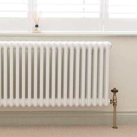
That would be my choice. Look at column radiators also. The 4 row ones out our plenty of heat. You can get then in just about every shape. Do your room heat loss and size for lower flow temps.
-
Take the actuators off on the not working loops, does the flow meter move down (the red lines). Removing actuator opens loop, regardless of call for heat. If this resolves issue you have an issue with electrics. If nothing changes you have an issue with air in the system, get the plumber back to bleed the loops. Takes all the junk off the UFH loop pipes. Look to box in, so they don't get damaged.
-
A little, or a lot depending on flow rates, if your at 20L/min and below very little, higher rates a bigger and bigger influence - if you have UFH you can do this at the manifold anyway. So wouldn't bother, unless you have a good reason.
-
The figure has nothing to do with that, it's your ventilation through put. Spreadsheet already assume very airtight build.
-
Cell B2, will be -3 in England, -5 Scotland. Cell B4 use 6 degs if well insulated Cell B2 is ground floor area only Cell B45 will give you your heat loss
-
PV and battery are separate to heating requirements, so not really relevant to question asked. There are some requirements for an ASHP often over looked and that is defrost - UK is pretty bad for it depending on exact location. Inland being better than coastal or near a big body of water. So generally it wise to oversize for the typical -3 design in the UK. Second is DHW generation, a small heat pump at design temp can take a while to heat a big cylinder as in a couple of hours. So you are better to look at a 6kW heat pump but make sure it has good modulation so it runs well for long periods of times for best CoP. The heat calculation, needs your ventilation system air changes per hour I would assume 0.5 to 0.3, and with MVHR efficiency circa 85 to 90%. You need to find average temp in your area for the monthly heating needs. You need window and door sizes, general roof, floor and wall areas and thats about it, with U values
-
Aren't both likely to change at the same, everyone with an EV charging at the same time, lo tariff becomes a high tariff period. You can't use one as justification and not the other etc. Not sure you would charge your house battery to then dump into your car. Then 5 mins later end up with a flat home battery. Some require it for anything other than basic functions. Some require for warranty, if control is from china who knows what will happen.
-
So how many radiators do you have
-
Or more complete cut and paste is Kilogram Definition: A kilogram (symbol: kg) is the base unit of mass in the International System of Units (SI). It is currently defined based on the fixed numerical value of the Planck constant, h, which is equal to 6.62607015 × 10⁻³⁴ in the units of J·s, or kg·m2·s-1. The meter and the second are defined in terms of c, the speed of light, and cesium frequency, ΔνCs. Even though the definition of the kilogram was changed in 2019, the actual size of the unit remained the same. The changes were intended to improve the definitions of SI base units, not to actually change how the units are used throughout the world. History/origin: The name kilogram was derived from the French "kilogramme," which in turn came from adding Greek terminology meaning "a thousand," before the Late Latin term "gramma" meaning "a small weight." Unlike the other SI base units, the kilogram is the only SI base unit with an SI prefix. SI is a system based on the meter-kilogram-second system of units rather than a centimeter-gram-second system. This is at least in part due to the inconsistencies and lack of coherence that can arise through use of centimeter-gram-second systems, such as those between the systems of electrostatic and electromagnetic units. The kilogram was originally defined as the mass of one liter of water at its freezing point in 1794, but was eventually re-defined, since measuring the mass of a volume of water was imprecise and cumbersome. A new definition of the kilogram was introduced in 2019 based on Planck's constant and changes to the definition of the second. Prior to the current definition, the kilogram was defined as being equal to the mass of a physical prototype, a cylinder made of a platinum-iridium alloy, which was an imperfect measure. This is evidenced by the fact that the mass of the original prototype for the kilogram now weighs 50 micrograms less than other copies of the standard kilogram. Current use: As a base unit of SI, the kilogram is used globally in nearly all fields and applications, with the exception of countries like the United States, where the kilogram is used in many areas, at least to some extent (such as science, industry, government, and the military) but typically not in everyday applications. Pound Definition: A pound (symbol: lb) is a unit of mass used in the imperial and US customary systems of measurement. The international avoirdupois pound (the common pound used today) is defined as exactly 0.45359237 kilograms. The avoirdupois pound is equivalent to 16 avoirdupois ounces. History/origin: The pound descended from the Roman libra, and numerous different definitions of the pound were used throughout history prior to the international avoirdupois pound that is widely used today. The avoirdupois system is a system that was commonly used in the 13th century. It was updated to its current form in 1959. It is a system that was based on a physical standardized pound that used a prototype weight. This prototype weight could be divided into 16 ounces, a number that had three even divisors (8, 4, 2). This convenience could be the reason that the system was more popular than other systems of the time that used 10, 12, or 15 subdivisions. Current use: The pound as a unit of weight is widely used in the United States, often for measuring body weight. Many versions of the pound existed in the past in the United Kingdom (UK), and although the UK largely uses the International System of Units, pounds are still used within certain contexts, such as labelling of packaged foods (by law the metric values must also be displayed). The UK also often uses both pounds and stones when describing body weight, where a stone is comprised of 14 pounds. Kilogram to Pound Conversion Table Kilogram [kg] Pound [lbs] 1 kg is equal to 2.2046226218 lbs
-
Strange until I joined the RAF (1986) I did the same, now its always metric so kg, and metres. Yes and 2.2 lb to the kg
-
ASHP with large thermal store (for load shifting)
JohnMo replied to apesort's topic in Air Source Heat Pumps (ASHP)
Not quite a few decimal places out it's 81,000 kWh. So if you if you pay have the cost to charge as normal rate 14p.v 28p you save around around £11k in electric less in the installed cost of battery and inverter. Just reading the current blurb on GivEnergy All In One (AIO) battery system, it is rated for an "unlimited" number of cycles within its 12-year warranty period, guaranteeing it will retain at least 70% of its original capacity. So on Cosy (3x charges per day) that could be a saving of around £20k less install cost. Install cost is higher but reward is higher again. -
Why - you are laying for the system to be installed so it will come with MCS certificate, which means you get paid for export, so why not sell the electric. DHW heating is fine if you don't get paid for export. Gas or heat pump DHW heating is around 6p per kWh, export around 15p on the correct tariff. I would look at a system that doesn't demand internet connection - GivEnergy does require internet, others no idea.
-
Why - I'm over 60 and was taught metric at school, it's been taught in school since about 1965! Only time since leaving I used imperial was working with equipment designed in 1940s. And ordering wood in imperial cross section (which it isn't actually that size - 147mm is actually 5.79" not 6") and metric length - but building industry is backwards in its thinking anyway, so cannot expect much different really.
-
Your boiler is a weather compensation boiler, so why not use it as one? Does your system follow the rules in the manual Note. Systems incorporating zone valves which could completely cut off the flow through the system must also include a bypass. The boiler does not normally need a bypass but at least some radiators on the heating circuit, of load of at least 10% of the minimum boiler output, must be provided with twin lockshield valves so that this minimum heating load is always available. Balancing 1. Set the programmer to ON. Close the manual or thermostatic valves on all radiators, leaving the twin lockshield valves (on the radiators referred to above) in the OPEN position. Turn up the room thermostat and adjust the lockshield valve to give an uninterrupted flow through the radiator.These valves should now be left as set. 2. Open all manual or thermostatic radiator valves and adjust the lockshield valves on the remaining radiators, to give around 20oC temperature drop at each radiator. 3. Adjust the room thermostat and programmer to NORMAL settings.
-
Air monitoring thingamajig
JohnMo replied to Russell griffiths's topic in General Self Build & DIY Discussion
Well done you. -
You may have an issue with the UFH manifold return leg collecting air? You will need a method to bleed the lower manifold and the piping run going to it. Also the return line you need an expansion vessel and safety group, something like this, after the filter isolation valves https://www.unventedcomponentseurope.com/expansion-vessel-25-litre-heating-fixing-t-bar-system-kit.html/?utm_source=Google Shopping&utm_campaign=Copy Unvented Components Europe&utm_medium=cpc&utm_term=879559&gad_source=1&gad_campaignid=17178278874&gbraid=0AAAAADCTOYDo74Yo9HePQuEMKnbFqfg6s&gclid=CjwKCAiA86_JBhAIEiwA4i9JuybXCf4Z5_Ln7s1jNmeqsPnHSW3goCc-0aIt_EChTwzn0-N3iEqenxoC5xkQAvD_BwE
-
Can't you get a filter in the vertical on the return after the tee? Then you only need one filter/strainer. I would redo the tee before you go through the wall, to make space. Rotate tee horizontal, add filter, then loop up and out off wall or something like that. Your pipe is huge so no issue with pressure drops feeding 3 loops
-
Looks like the party is over....
JohnMo replied to Beelbeebub's topic in Air Source Heat Pumps (ASHP)
Yep. You certainly have nothing to complain about if you don't vote, you are obviously happy with everything, anyone throws at you. -
So basically all the gaps you see need to be filled. I would look to use a good expanding foam. Some of the vertical filler pieces of PIR, don't look to butt up against the OSB roof cover. All PIR needs to be hard up against that.
-
GOVERNMENT LOOKING TO RETROSPECTIVELY CHANGE FIT TARIFFS
JohnMo replied to dave1967's topic in Photovoltaics (PV)
It's is actually buried in here -
GOVERNMENT LOOKING TO RETROSPECTIVELY CHANGE FIT TARIFFS
JohnMo replied to dave1967's topic in Photovoltaics (PV)
There was a thread on this the other day -
Air monitoring thingamajig
JohnMo replied to Russell griffiths's topic in General Self Build & DIY Discussion
Are you sure, you should have CO for carbon monoxide - not CO2 for carbon dioxide. We breath out CO2, cars, boilers and gas hobs put out CO.

