MortarThePoint
-
Posts
2198 -
Joined
-
Last visited
Everything posted by MortarThePoint
-
A 25mm SDS bit would leave only 15mm of block between the holes. That's removing 63% of the material. Surely it's not a good idea to weaken a wall to that extent across 1.2m of width.
-
I presume you mean drill from the lower left which is the utility. It would be no drama for a few, but having a line of holes at 40mm centres isn't so appealing. I suppose I could stagger them vertically as well to make the hole c/c about 60mm. It's still across about 1.2m of wall if going fully 1:1 radial. Watched some videos of people core drilling at 45 degrees but that's with a pretty beefy jig.
-
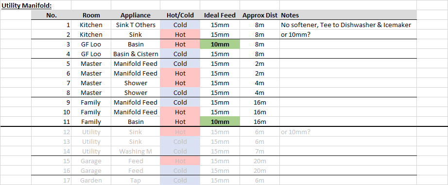
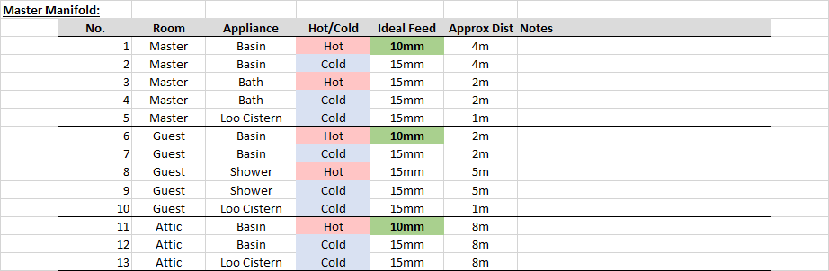
Ignoring the Kitchen feeds, which may be able to be down low and so much more choice there, the 38mm core holes could be split as follows: That's a total of 4 core holes vs the 1:1 needing 10 (exc. kitchen). The compromises are: Master Cold manifold feeding bath, basin and loo cistern. May make sense to just use accessible Tees. Items not individually isolatable. Guest Cold manifold feeding shower, basin and loo cistern. May make sense to just use accessible Tees. Items not individually isolatable. Family Cold manifold feeding shower, bath, basin, and loo cistern. Would be kept accessible but items not individually isolatable. Family Hot manifold feeding shower and bath. That's effectively a Tee. Would be kept accessible but items not individually isolatable. One of the holes has 3no. 15mm Hep2O pipes in. That is a squeeze and may require some different conduit (3no. 15mm circles fit in one 32.5mm circle and the solvent weld pipe I am using as conduit is 32mm ID). Attic is a future renovation opportunity to add a loo. There are two compromises here (a) it is 10mm hot and cold (b) it's hot is shared with three colds so not ideal but feels minor. Those feel like minor compromises for the significant benefits of reduced core holes and pipe grief. The coarsest level of isolation is at the room level (Family H & C, Master C, Guest C). In terms of in use, I think the only compromise is: It does have the Guest loo cistern feed from the same main 15mm pipe as the Guest shower (cold). Probably worth stepping the loo cistern down to 10mm to hopefully keep the shower as the preferred path, though I could adjust the cistern inflow if required. Basin is also fed off this, though that is less binary than the loo filling. I don't expect the bath and shower in the same room to be run at the same time.

-
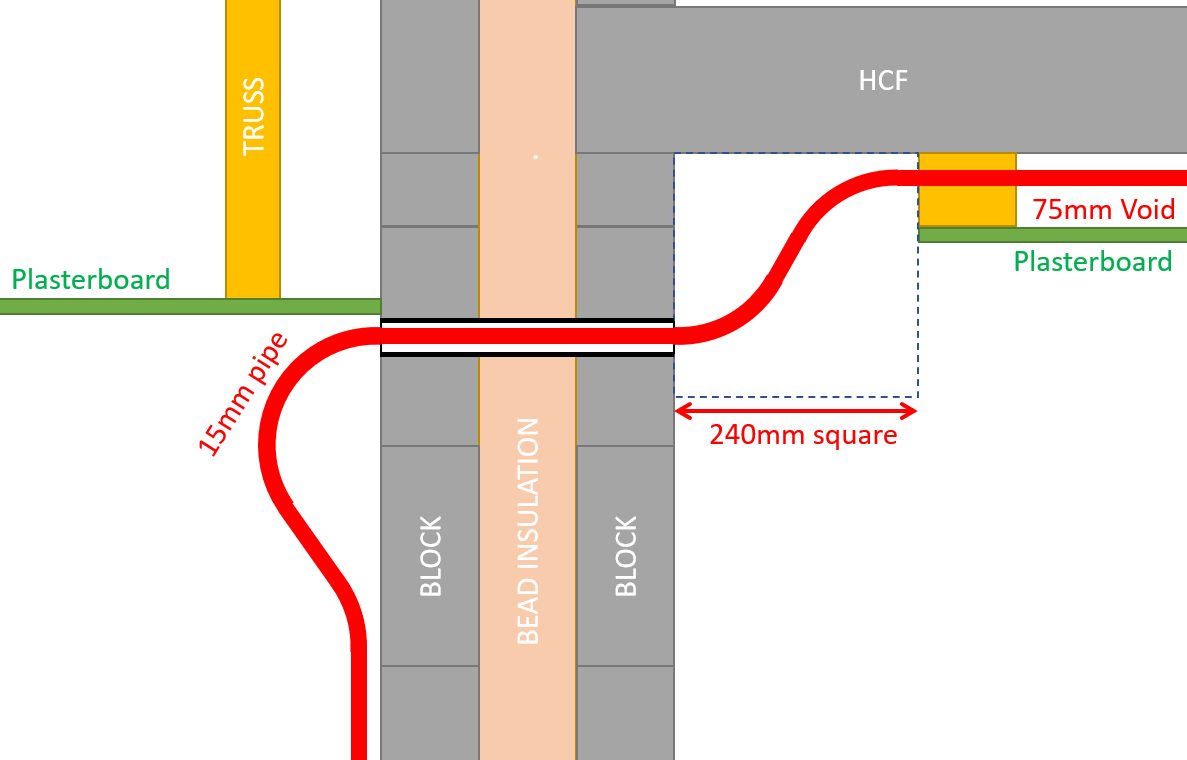
The S-bends can be eased but using the dimension in and out of the diagram to help a little.
-
That's fair, it could have been thought out better. I am going through first fix and catching up some of those now. I wasn't aware of the manifold approach at design time and presumed I'd just have two pipes coming through, plus heating & wires. I know a normal builder wouldn't be worry about this in the slightest and would have the whole house off two pipes with Tees and Elbows a plenty. But that's not how we all roll around here which is good. The kitchen ceiling on the right of the diagram has Hollow Core Flooring (HCF, precast concrete) which is easy enough to drill through vertically, but not practical to route into the surface. Some suppliers provide that at design stage, but not mine. I'll have a suspended plasterboard ceiling (on the Gyplyner system) giving a service void of around 55 - 75mm (HCF is designed slightly bowed and may vary a bit by room). The Utility, left of diagram, is single storey and so the plasterboard ceiling will be screwed to the roof trusses. The layout of the house is such that the Master bathroom and Guest bathroom are immediately above that Kitchen/Utility wall. In other words, higher up that Kitchen/Utility wall turns into the exterior wall of those bathrooms. The cylinder is well placed close to all outlets except the Family bathroom which is at the other end of the house. The fly in the ointment is getting through the blockwork cavity wall. Actually, only the Family bathroom is served via the full S-bend. To most other outlets the pipes will need to head straight up. Part of this whole game is rolling with the compromises and trying to make them as risk free as practically possible. I only really have three four options at this stage: Utility Manifolds : totalling around 30 ports and running that many pipes (plus heating and wires) through about 12 core holes. Occupying the top corner of the room (above or inside kitchen wall cupboards) with some of the pipes' s-bends. Kitchen Manifolds : minimal pipes (2 core holes) through wall then 30 ports and and pipes. Manifold housed in the top corner of the room (above or inside kitchen wall cupboards). Satellite Manifolds : Smaller Utility manifolds, fewer wall holes, local accessible manifolds. Still a small amount of space taken up above/inside kitchen wall cupboards. Go through the wall higher up : It's occurred to me I could go through the walls to the Master and Guest bathrooms in the roof space. I would have to insulate around all the pipes and ensure they get warmth from below, but it's an option. Having once upon a time walked into my in-lasws' house with a burst loft tank raining inside, I am keen to avoid any pipes going anywhere near unheated spaces. I was the one who discovered the flood. Strange walking inside from the rain outside and into the rain inside before turning the light on.
-
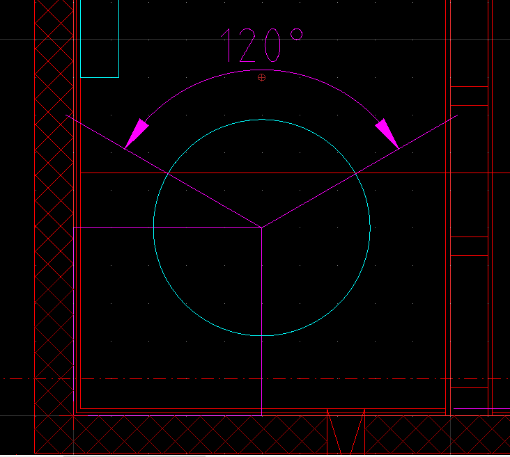
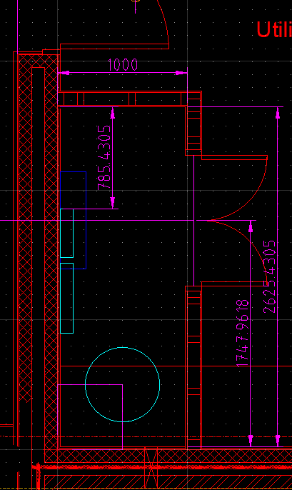
@Nickfromwales and @TerryE This is the awkwardness of the pipe routing through the Kitchen/Utility wall. The diagram is to scale. I don't think I could core drill at an angle which would otherwise help greatly. It already looks like I'll need to box in above the kitchen cabinets for this reason.

-
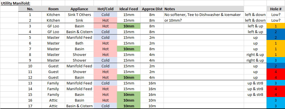
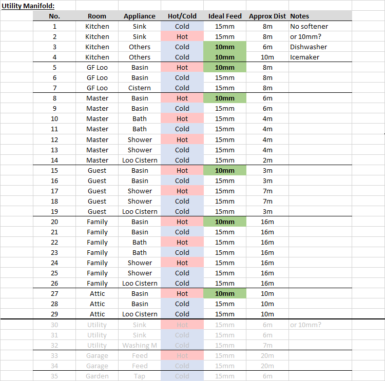
Below is a comparison between satellite manifolds and a 1:1 radial arrangement. Greyed out doesn't have to pass through the wall. In the 1:1 Radial arrangement, 29 pipes (17no. cold 15mm, 2no. cold 10mm, 6no. hot 15mm, and 4no. hot 10mm) have to pass awkwardly through the Kitchen/Utility wall. In the Satellite Manifold arrangement that comes down to 11 (5no. cold 15mm, 4no. hot 15mm, and 2no. hot 10mm). The Satellite Manifolds would have to be accessible, but wouldn't necessarily feature shutoffs. 1:1 Radials: Satellite Manifolds:

-
Servicing loos and basin colds with 10mm would halve the number of core holes I drill for cold if using 38mm core drill. Such a hole allows 32mm pipe as conduit and 2x 15mm and 2x 10mm within (or 6x if only 10mm pipes). Otherwise I need 11x 38mm core holes for all pipes. I've wondered about 78mm core with downpipe conduit. Unfortunately, a letter box isn't practical. Would be better.
-
It's quite tough 10N aggregate block so harder work, but not the main concern. I don't think flows would suffer as I don't expect the bath and shower in a room to be running at the same time. Satellite manifolds would only service one room. All pipes passing through will then need to bend down to go to the manifolds, so that will be a bit tricky. Added to that is the plant room ceiling is 150mm lower than the kitchen ceiling void where all the pipes come from. I need to box an area out for all this above kitchen cabinets and have even wondered if I should put the main manifolds there. All that said, I appreciate your experience and an trying to see if I can do 1-1.
-
Doesn't sound like there is any point in getting a twin coil cylinder then in my case. Any future oil based changes would be grievous anyway and probably not be impossible with only a single coil. Spacing heating is the lion's share of heat demand anyway and doesn't affect the cylinder.
-
Interesting, I didn't know such a thing existed. I think there is only one model that is pretty large and incorporates a 17kW ASHP (15-26kW oil). This hybrid is about £3k more than the straight ASHP 17kW unit.
-
I thought check valves and non-return valves where the same thing
-
I assumed it was for drawing convivence. Cylinder drawing and coil placement is just a rough sketch so don't worry about placement or indeed if I have the FLOW and RETURN connected the right way round 🙂
-
I'm trying to see if I should hedge my bets. I have been currently quoted a single coil cylinder (3.0m2) but there is a twin coil (2.2m2 + 1.0m2) option I could ask for which adds about £60. I'd rather not ask for it as I have been quoted without and I don't want to upset things, but I don't want to miss a trick. I don't think I would be going solar thermal and PV could just use the ASHP or immersion heater I guess. I could possibly imagine two future changes: Adding an oil boiler as a dual source option Adding a wood burner with back boiler
-
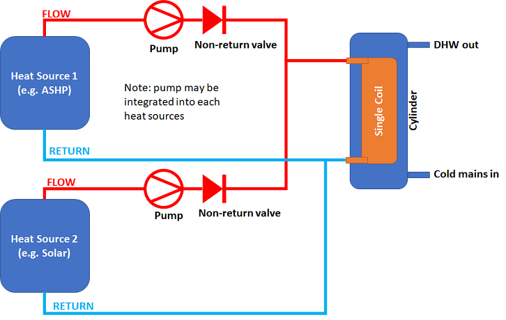
OR gate but importantly not an XOR gate 😀 That said, if they were pressure driven pumps, rather than positive displacement driven, then one pump would bully the other closing that one's non-return valve and mean you only have the stronger pump circulating. You'd want positive displacement pumps. I think you could solve it with pressure driven pumps by using pressure regulators after the non-return valves, but you'd not start there.
-
Perhaps a daft question. @Nickfromwales or @TerryE you probably know the answer. I understand that one way of connecting two heat sources to one cylinder is to have two coils in the cylinder itself, but can't you achieve the same thing using two non-return valves and a single coil? Example diagram below. Reasons that come to mind for two coils: Is it because the two heat sources may need different Return temperatures to be operating most efficiently? That assumes the Return temperature is not at the temperature of the water in the cylinder, which would be the case with maximum heat transfer. Also that would only be a problem if using both heat sources at the same time. Is it more to do with one heat source being used to heat one part of the cylinder and the the other another part of the cylinder?
-
I'll have to remind myself which I decided against individual pipes per appliance. On thing I don't like about it is the shear number of pipes I have to pass through a cavity wall which currently doesn't have holes in it for the pipes. If the local manifold is accessible, you don't end up with many more connections than without a local manifold. Consider for example a 3 appliance bathroom (shower, loo, basin) The connections are as follows Local manifold: at main manifold, 4no. at local manifold, 3no. at appliances --> 8 TOTAL No local manifold: 3no. at main manifold, 3no. at appliances --> 6 TOTAL It feels unlikely that I would need to isolate one appliance whilst keeping the rest of the room operational. On a statistical basis: You are almost 3 times as likely to have an issue with a long inaccessible pipe crossing the house than if you just have the 1 such pipe. Chances very low still though.
-
I was hoping that most of the stuff that would need access on the cylinder would fit on the front 120 degrees of the cylinder and have reasonable access. The plan was for the tank to go in before the wall is put up, but that tempts the installer to put something somewhere difficult. I am planning to fit a computer fan (120mm) to blow air out of the cupboard. They push about 90m3/h = 0.025m3/s and the heat capacity of air is around 1kJ/m3K. That means a 120mm computer fan can remove 0.025m3/s * 1kJ/m3K * 10K = 0.25kW with the cupboard 10C above the neighbouring room's temperature. The cylinders loss figure is about a third of that, so I should be OK (hopefully). There will be loss from the UFH too, but I could always add another fan. Cold manifold is one feed per room that uses water (all 15mm), garage and outside tap. DHW manifold is 10mm to 4 basins (3 bathrooms, 1 loo), 15mm to 3 showers* and 1 bath, 15mm to Kitchen, 15mm to Utility, 2 spare. Feels like adding a spare or two to the cold. Note: two of the showers are about 6m run from the manifold, the third is about a 15m run and (*) actually shared with a bath which will mostly be used more as the children grow up so waiting for hot isn't too bad. I have run the numbers on this before and they looked OK (10 seconds per 15m run at 10l/min shower, pure hot). I keep hearing people say I should have a Water Softener, but have never liked how the water 'feels' or tastes with them. I'm near Cambridge, so water is hard but not mega. I expect shower TMVs are the main risks with this so keeping them accessible (one through a hatch in the wall) and the other two are on shower bar so readily replaceable. We've had the same kettle with this water for ages, but do use a Brita filter (which gets replaced very infrequently). Network rack is going under the stairs with the other GF UFH manifold (toasty, so another venting computer fan or two is likely). I'm far from Passive Haus standards so have to have a boiler/ASHP and so makes sense to use it to heat the water. I do wonder if I might regret not having a secondary tank coil, but don't currently have plans for anything that could use it. Possible future PV could be hooked up to this tank's immersion heater I presume. Without the experience, I have to think it through ahead of time rather than rely on instinct. Many a time have I stood on site staring at something wondering what 'the right way to do it' is. Equally, sometimes you just have to get it done and move on.
-
Sorry, cross post. Is it not relevant to Stainless Steel though?
-
It's a stainless steel cylinder so is that only relevant to copper cylinders? It's not going to be the official Mitsubishi one as there have been issues with supply. Here's a thread on the cylinder: But this is the datasheet:

-
@Nickfromwales I guess it's the fact it's sacrificial and so wears out.
-
Fabdec Stainless Steel Cylinders
MortarThePoint replied to MortarThePoint's topic in Boilers & Hot Water Tanks
PDGF link doesn't work so here it is as an image: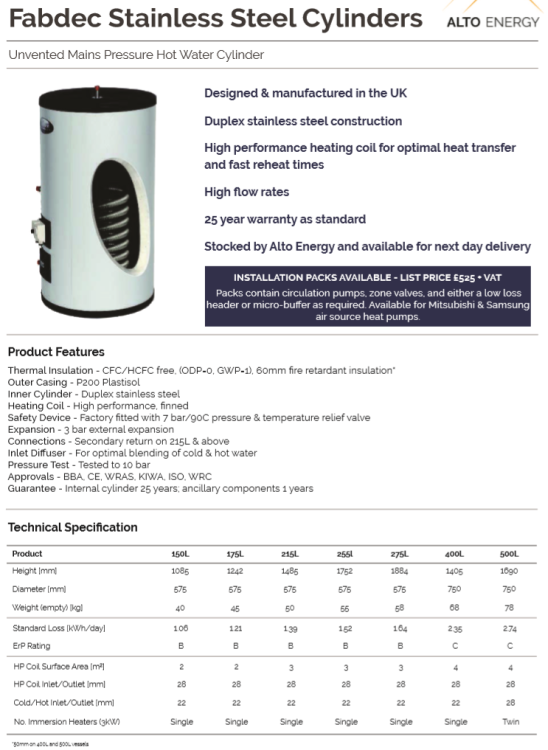
-
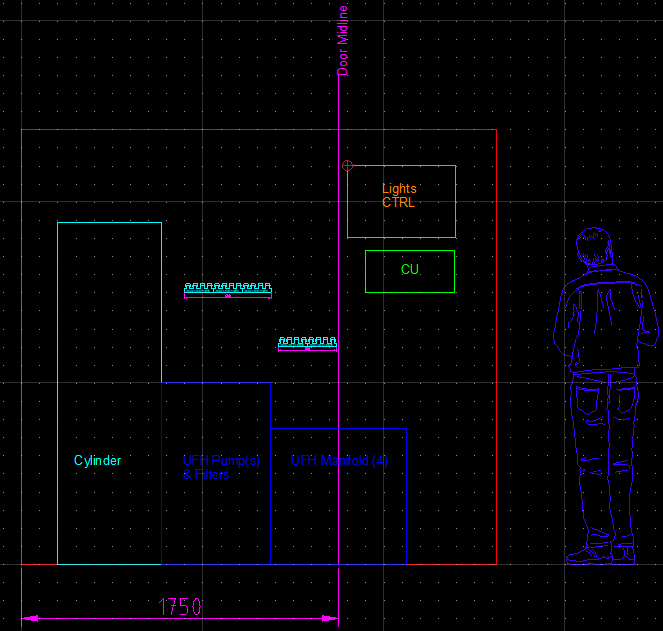
I've just ordered my ASHP & Cylinder package and am progressing my planning out of the Plant Room / Cupboard. The house design leaves a small room 1m x 2.6m for the following: DHW cylinder (ASHP): has a reasonably small footprint 575mm circle), though will no doubt have pipes all over the outside. Plan to leave extra 200mm all round. It is very tall, ~1800mm. DHW and cold water manifolds ASHP controls: Mitsubishi Ecodan. hopefully doesn't take up much space UFH primary pump and filters: I am going with a single large pump pressure driving a 3 manifold system. If I get issues, I can later add pump(s) to manifold(s), but no more space needed in Plant Room. UFH manifold: 4 port, 3 used. Plus controller. Electrics CU: 3-phase connection. This will be many way as I am having lots of circuits. I will also have a feed to the garage, which may be in a separate CU box. I guess it could end up as actually being 3 CUs, one for each phase where the phases are slit House / ASHP / Garage. Lighting control: a metal cabinet housing relays and control circuitry for the lights Battery bank: Potential to add this later. Server rack style. May choose to have it outside the house (e.g. garage or meter kiosk) Forgotten something? Rough layouts below. Walls & Floor Finish: Before the ASHP and DHW cylinder work can start, I need to decide what I am doing about the walls and the floor. They are currently bare blockwork and screed respectively. For the walls I see three options: As a minimum, I would seal the blockwork with Passive Purple for airtightness Wet plaster the walls and paint Simple tile As for the floor, I see four options: Leave as bare screed Seal with a paint (like garage floor paint) Simple tile Tank and create some form of sump around the DHW cylinder. Would need a drain provision though What have others done with their plant rooms?
-
But for it being super weird, there is a lot of sense to having the manifold on the ceiling shooting out its however many pipes horizontally off to where ever they need to go. Not very accessible (would need steps) but avoids the need to send each pipe up about 1000mm and then through a right angle into the ceiling void of the room next door. Feels too weird though. I could just imaging the look on a professional's face if they saw it.
-
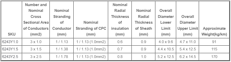
Some useful dimensions for 3&e cable: https://www.expertelectrical.co.uk/6243y-cable#product-specs-dimensions