MortarThePoint
-
Posts
2198 -
Joined
-
Last visited
Everything posted by MortarThePoint
-
These HDMI cables from Lindy are slim but importantly have a compact connector (7mm x 16mm apparently) that should fit through 25mm conduit. Up to 4.5m long. Not cheap at ~£10/m. Connector: Dimensions (approx.) WxDxH: 19x16x7mm (0.75x0.63x0.28in) 21x16x7mm (0.83x0.63x0.28in) for connector with chipset Cable: Jacket Diameter: 3.2mm (0.13in) Spec: Supported Bandwidth: 10.2 Gbps [so not 18Gbps] Maximum Resolution: 3840x2160@60Hz 4:2:0 8bit https://www.lindy.co.uk/cables-adapters-c1/audio-video-c107/4-5m-cromo-slim-high-speed-hdmi-cable-with-ethernet-p11688 https://www.amazon.co.uk/0-5m-CROMO-Speed-Cable-Ethernet-Black/dp/B01ANI2ICQ

-
I agree, but it is a common choice these days. I was wondering if you could get an articulating backet that would allow the TV to be lowered by a couple of feet. I could make such a thing, but that would become a project in itself. Perhaps I should have a sofa that jacks up on stilts 🤣
-
Looks like you can get a lot for your money (£379), this includes all sorts. Last year's model but I plan to have it for more than a year 🙂 Under connectivity, it says "Optical connection". Is that for audio, i.e. SPDIF? EDIT: Seems to be https://www.argos.co.uk/product/9336342?clickPR=plp:2:74

-
Good shout on the double socket with USB. I am planning to route Ethernet there as well. I may struggle to get 3 HDMI cables there. I was wondering if I could just use an HDMI switch, but that could rule out screen-in-screen if that is available on the TV (i.e. most of screen showing one input with a smaller window showing another input)
-
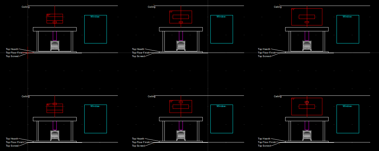
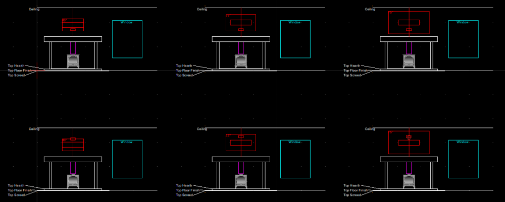
These things are huge! A 55" TV is probably considered the minimum for a new TV and they start at around £250, Wow. Below are some layouts with the connections below the mount and above the mount as @ProDave suggests. In reality, the 40" TV would get raised up slightly. The mount shown is the Tilt one in the original post. The 55" and 75" options look more in proportion. Perhaps the 75" dominates the space a bit? The mantel piece shown is actually the Concrete lintel (215mm high) which I had thought to dress with something, but I guess it doesn't have to be exactly the same height.
-
I would probably have speakers at the back of the room and a soundbar would be nice, but might be hard to keep it clean looking. Can you put a sound bar in a coffee table?
-
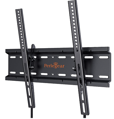
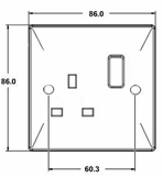
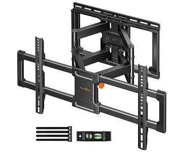
I've been living under a stone for the last 7 years without a TV, but plan to have one in the new house. I want to put the required connections above the fireplace mantel for it but don't want then to clash with whatever TV mount I go for. I plan to route a 1-gang mains socket and two HDMI cables. I have found that 1no. HDMI cable can be passed down a straight length of 25mm round conduit. There may be HDMI cables that could be squeezed down 25mm oval conduit, but not the standard cables (may try sanding one down). The main question is where is best to place these connections so they don't clash with the TV bracket? Looking at a few bracket designs (examples below) side by side on the vertical centre line looks a reasonable choice. The first shown below looks smaller, but most Perlegear tilt mounts have an 8.46" high wall plates. Their multi motion ones are around 10". A TV display is half its diagram dimension high, so a 40" TV should just hide a 1-gang socket centred up to 200mm below the TV's centre line. If I centre the 1-gang at 200mm I think it would allow a mount wall plate height of up to 2*(200 - 0.5*86)) = 314mm = 12". Even the largest mount I have seen has a wall plate less than 12" (42" to 85" TV full motion example below). I expect the wife is going to want a shooting gallery of kitsch under the TV, so I imagine the bottom of the TV will be about 250mm above the mantel piece. I can then centre my connection points 300mm above the mantelpiece and all should be OK.
-
Routing Plumbing along stair stringer
MortarThePoint replied to MortarThePoint's topic in General Plumbing
Would you just use standard pipe clips or would you try to isolate the vibrations somehow. One though that comes to mind is to use a pipe clip that is big enough to go round the insulation and add some compliance that way. -
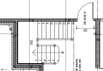
Happy New Year everyone! We're having a staircase with a half landing under which the UFH manifold is going for GF. The only realistic route* to this manifold is to run pipes within the staircase. We are having a staircase with straight stringers either side and a panel underneath, so you can't see the backs of the treads and risers. This will leave a space which I intend to use for routing the UFH flow and return feeds, as well as some mains and Ethernet etc. Good plan? Things I need to understand: I've no concerns about the wires, but how will the pipes handle the vibrations of people going up and down the stairs. I remember jumping around on the stairs as a kid so it can be quite a bang. I am tossing up between Hep2O and copper for these feeds. Heat affecting the timber of the staircase. I guess I could insulate the UFH feed pipes well enough to reduce this concern(?). I could also add a 120mm computer fan to blow air through the space if that could help. * For completeness, I guess an alternative is to create a false wall under the stair that the pipes are routed in along the surface of the blockwork wall which is already there. That is more work/cost and takes up space.
-
Howdens seem OK on the one I have so far opened :-)
-
Thanks, is that 16mm of just HardWall base to then have the finish skim as extra? When you say plained back around casings and beads does that mean the finish layer is thicker there then?
-
This feels like such a daft question, so sorry. I have Blockwork walls to be wet plastered (HardWall + MultiFinish). As I imagine it, the lining depth should be the sum of - 2no. (i.e. 1no. on each side) MultiFinish skims 2mm each - 2no. HardWall base 11mm each - 1no. "100mm" block 96mm TOTAL: 122mm But linings are 108mm or 132mm finished depths? Howdens Door Lining Kit Am I missing something or should I be ripping them down to 122mm? @nod I hear plasterers hate linings being wrong so what do you suggest? Am I too thin on the MultiFinish layer?
-
Merry Christmas ⛄
-
ASHP vs Oil in 2022
MortarThePoint replied to MortarThePoint's topic in Air Source Heat Pumps (ASHP)
Yes cheap by comparison -
ASHP vs Oil in 2022
MortarThePoint replied to MortarThePoint's topic in Air Source Heat Pumps (ASHP)
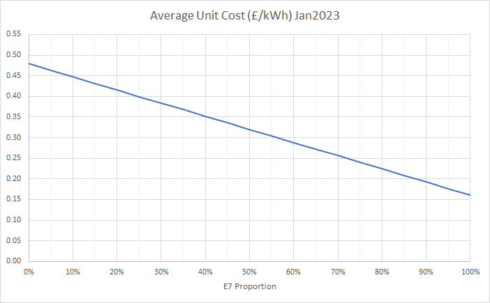
I've expanded my model a bit to consider each ambient temperature and its probability of occurrence. Factoring in Our intended ASHP (Ecodan 11.2kW), but not modelling capacity variation with temperature, I calculated an average COP of 3.9 and an average of 87% coming from E7 electricity. Inputs: SAP numbers for heat demand to work out a fit line of heat demand vs ambient temperature (14 - T_ambient)*250 kWh/month in my case Cambridge weather numbers to get normal distribution mean and standard deviation (10.57C and 6.57C) ASHP capacity (11.2kW) and cubic fit to their COP curves based on range of flow temperatures Flow temperature of 35C which should be possible as I have UFH on both floors. That 87% figure ignores: Any heating requirement outside of optimised hours (e.g. for defrost or comfort) Domestic hot water heating I expect 80% may be more realistic for space heating and the DHW may lower that further(?). Our supplier (not sure if will be for new house) has a ration of 3:1 between their normal rate and E7 rate: That makes the cost of electricity for the ASHP vary as follows depending on what proportion is E7: So I'm probably looking at electricity costing 22p/kWh for the ASHP and with the average COP of 3.9 that makes heat cost 5.6p/kWh. Oil at the moment is expensive at around 80p/litre, so 7.7p/kWh (80p/litre / 10.35kWh/litre). [saw Black Friday price of 74p, seeing 81p-89p now] If I were to use the 'without government support numbers', the ASHP would average 47p/kWh electricity and 12p/kWh heat. Historically, a more normal price for oil is around £55/litre I think. That leads to near parity with oil costing 5.3p/litre (5% cheaper). I haven't heard that the government is subsidising heating oil at the moment, so I wouldn't be surprised if the future looks a bit like Electricity consolidating around the subsidised price and oil coming back down to 55p/litre. Still no clear winner on price. That's all crystal ball stuff though. If you have a leakier house which needs a higher flow temp, giving lower COP, and stretching the ASHP more, lowering the E7 proportion, an ASHP is clearly a disaster.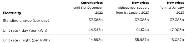
-
A word of caution - check your trades material costs
MortarThePoint replied to Moonshine's topic in Project & Site Management
I don't know what other peoples experience are, but I doubt the tradie is very motivated to worry about the cost of the materials if they are passing it straight on, so he may not have noticed. I always have a a conversation with the BMs that starts with a silly price and then settles on what feels a reasonable price. Even with the same guys week after week, they never go straight to a sensible price. I don't like it as I always feel the price could have been less and never know if I have actually got a good deal or not. I doubt tradie is going to bother with any of that if he's passing it on. -
Fabdec Stainless Steel Cylinders
MortarThePoint replied to MortarThePoint's topic in Boilers & Hot Water Tanks
What is the benefit of twin coil? Do you have solar thermal or something, or is it about giving you the ability to just heat the top of the cylinder? -
Cold Temperatures Before Central Heating
MortarThePoint replied to MortarThePoint's topic in Boilers & Hot Water Tanks
Yes, internal storage. It's good. I've a load of Xioami Mijia as well but this has three pluses over those: - data logging - unencrypted BLE beacons making it easy to make your own data aggregator - Cheap AAA batteries I haven't seen a teardown so don't know the sensor they've used but their claimed accuracy is good. Not so cheap though at £11.50 if you get a pair -
Fabdec Stainless Steel Cylinders
MortarThePoint replied to MortarThePoint's topic in Boilers & Hot Water Tanks
The Alto PDF lists it as 3m2 which is the same as the Gledhill. I can't see a number for the Valliant. I guess the greater the area the more quickly you can heat the water. -
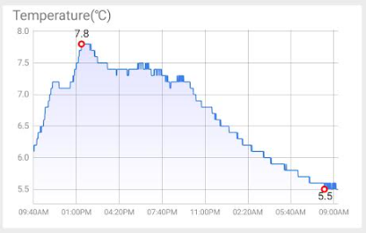
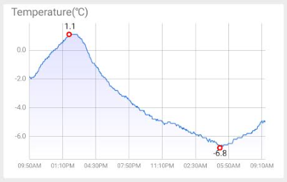
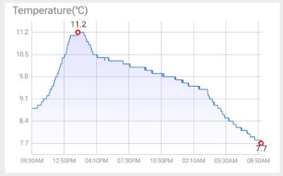
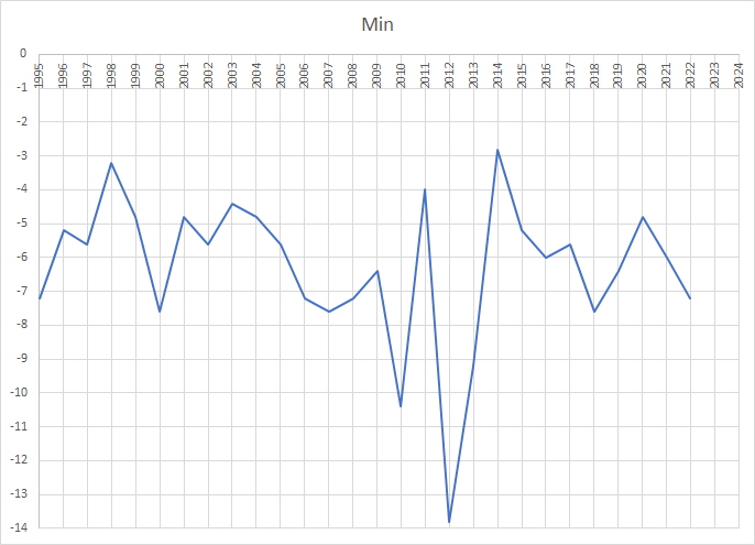
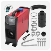
How are others coping on site with the cold temperatures? I thought I would share what I'm doing, which could probably be a fair bit better. We don't yet have central heating in the build. I've set up a cheap "Diesel Heater" from eBay that I'm using Kerosene in. There aren't many of the "All In One 5kW" type left on eBay like the one we have: Last night was properly cold, below -7C in Cambridge which is below most year's minimum (bottom third 1995-2021). We recorded -6.8C in the garage (no doors) and the kerosene heater upstairs in the house stopped at around 3am unfortunately (-6C in garage), so the temperature dropped there more quickly. We're putting about 2.3kW of heat in (heater set to 3Hz to make 5L last ~24 hours) from the Kerosene heater plus the log burner downstairs, but that stopped at around 10:30pm. I'm surprised the log burner can't raise the temperature downstairs more than ~7.5C but there are quite a number of drafts / weak points downstairs (e.g. Polythene over a 2.2m x 2.1m door opening which has some gaps). I'm quite pleased that we can keep the temperature in the house above 8C upstairs (bar it stopping) and above 5C downstairs in such an extreme outside temperature. I was hoping for 10C or above, but these are extreme temperatures (for here). Only upstairs is MF framed and plasterboarded so far. So far the loft only has 1 layer of 100mm / 150mm Loft Roll (44) with some areas not yet done. The walls have been blown with their cavity insulation (beads). All windows are in but not all doors. I have a dehumidifier running to take some of the water away that the heater will be producing. Garage: Upstairs: Downstairs: Cambridge Weather Station minimum temperatures calculated in Excel: ThermoPro TP357 Bluetooth Hygrometer Mini Room Thermometer: https://www.amazon.co.uk/gp/product/B093PT1NL1/

-
Fabdec Stainless Steel Cylinders
MortarThePoint replied to MortarThePoint's topic in Boilers & Hot Water Tanks
Interesting, must be different then. Other that kWh/day heat loss, being stainless steel and the number of immersion heaters what else is worth looking for? -
Fabdec Stainless Steel Cylinders
MortarThePoint replied to MortarThePoint's topic in Boilers & Hot Water Tanks
Hi @Nickfromwales sorry to call you out but you've normally got some good thoughts on these things. -
Fabdec Stainless Steel Cylinders
MortarThePoint replied to MortarThePoint's topic in Boilers & Hot Water Tanks
The 275L tank has a heat loss figure of 1.64kWh/day so 68W which is better than the Gledhill Stainless Lite Plus (~80W) and Grant QR (2.1kWh/day) but a bit worse than the Valliant ones (1.5kW/day). Each 0.1kWh of heat loss is probably 0.025kWh of electricity, so at 40p/kWh that would 1p/day, £3.65/year. The Fabdec would be 16.4p/day so £60/year. It only has one immersion heater, is that a concern? -
Does anyone have one of these or know anything about them. My ASHP quote (11.2kW Ecodan) has the 275 litre one listed as the tank included. This is all the information I have: DHW Cylinders.pdf The information from Alto Energy doesn't say it's an Excelsoir, but here is that brochure: https://fabdec.com/wp-content/uploads/2022/12/Excelsior-Brochure_221103b_lq.pdf That doesn't list 275 litre option, but Fabdec have no other range listed based on a quick look at their website (https://fabdec.com/en/water-heating/)
-
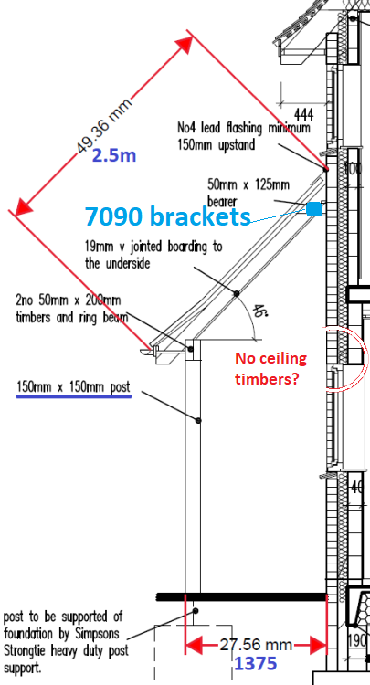
Ah, I think I may have misunderstood you. Are you saying that just having 7090 brackets at the top is sufficient and then there wouldn't need to be any ceiling ties at all? So like this: