Jump to content

MortarThePoint

Members
  • Posts

    2198
  • Joined

  • Last visited

Everything posted by MortarThePoint

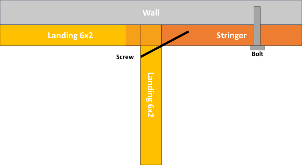
  1. Has anyone successfully claimed VAT on their energy storage battery or hear of it being done? Same goes for the inverter charger. Might wall mounted ones be more 'claimable'? I'd like a battery system and need to size it for expected ASHP demand, but probably something like 15 - 20kWh. That's 3 or 4 server rack batteries a charger and hybrid inverter (are they combined?) So probably looking at £6k+VAT. Would allow me to effectively use E7 electricity during the day when air temps are higher so COP better. I expect I would need to have an inverter capable of sustained 5kW to allow ASHP at full wack, lights and cooking. Options I'm considering: Fogstar 5.12kWh: https://www.fogstar.co.uk/collections/server-rack-batteries Fox ESS LV52: https://www.itstechnologies.shop/products/fox-ess-lv52-5-12kwh-48v-battery-module Pylon US5000: https://batteryfactory.co.uk/products/pylon-us5000-4-8kwh-li-ion-solar-battery-48v Premium Lithium system: https://premiumlithium.com/products/tripod Solis hybrid inverter: https://www.ginlong.com/global/inverter.html Useful resource: https://dcguy.co.uk/server-rack-battery
  2. I thought I would share by deliberations on pipes for the feed and return to UFH manifolds. I have an 11.2kW ASHP and two main Manifolds meaning the peak power a manifold is around 5500W. Based on a dT=5K, that works out as a flow rate of around 5.5W/(5K*4.2kJ/K.kg) = 0.26kg/sec = 943kg/h = 0.94m3/h. My head calculations when considering a circulation pump were based on 28mm Hep2O. I was considering using 26mm multilayer pipe with compression fittings, but it turns out that would be much more resistive (~55% more) and the higher flow speeds would also be noisier. I expect a peak flow to a manifold of around the 946kg/h line of the table. For the multilayer pipe that works out as 4.27mbar/m or 154mbar=1.54m of head loss for a 36m run. Hep2O on the other hand the drop would be 0.276kPa/m=2.76mbar/m or 99mbar=1m of head loss for a 36m run. That's a 55% difference. If flowing 50% of the time, the difference in electricity use would work out as (24*365*50%) * ((0.26kg/3*9.81N/kg*0.55m) / 50%) = 12.3kWh/yr. Not much. I'd be more worried about being closer to the 1m/s advisory limit for flow rates based on noise. The multilayer pipe has the advantage of holding a shape when bent to it and more reliable fittings. It doesn't suit my situation though as I can't easily change to the larger 32x3.0 size that would be needed. 28mm Hep2O looks to be the better choice.
  3. One aspect this neglects is all the bends in the UFH pipe. They aren't sharp bends, but with a bend radius of around 12.5x bore if a 90 bend or 6.3x bore if a 180 bend. Using this tool [1] I get pressure drops due to bends of these sizes of equivalent added length of 67mm and 96mm respectively. There is one such bend every ~3m so that's a pretty small addition of around 3%. [1] http://www.pressure-drop.com/Online-Calculator/
  4. @JohnMo When you are running less than peak power, the flow temperature goes down, but does the flow rate go down too? I guess it can go down since the water dT between room and water is lower and so to get the same flow vs return temperature difference, the flow would need to slow down. I expect to be optimal, you want the dT of at the ASHP to be the same as the dT at the UFH manifold. That wouldn't be the case though since I think the ASHP circulation pumps will run at constant speed.
  5. Both pumps would be around 50% efficient. The Ecocoirc-L running at 4m and 2.31m3/h would be 50W of shaft power which I guess is the same as electrical input. The Ecocirc-M at 3m and 2m3/h would be 33W of shaft power. If that is the electrical powers too, then using the Ecocirc-M would save 149kWh/yr = ~£50/yr. It's running closer to its curve limit. Not sure what that means in terms of lifetime.
  6. I kin of expect my operating point to be at a head of 3m which is better suited to the Ecocirc M (3m constant pressure setting) than the Ecorcirc L (2m & 4m constant pressure settings]. However, 2m3/h would put it right near the maximum flow rate for the Ecocirc M at 3m head. Running the pressure 33% higher (at 4m rather than 3m) would put up the flow rate by 18% [1.33^(1/1.76)=1.18] and the hydraulic power by 57%, probably the electricity consumption too.
  7. Here's a video of just attaching it to the stringer https://youtu.be/Pmyaw2TPUhk
  8. Thanks How far does the first step of the upper flight overlap the half landing frame? I've designed it so that the riser is flush with the frame edge and it's only the nosing overlapping. That doesn't allow for any intermediate (internal structural) open stringers to notch on to the landing frame which would be nice for support. I hope that makes sense.
  9. JAS Timber offer a service of cutting the mortice and tenon for you, but they are in Lancashire which is far from me in Cambridge. https://www.jastimber.co.uk/newel-mortice-stairs-1-tenon
  10. Below is an example of the Newel / Stringer mortice and tenon. @dnb I see you've just installed a Stairbox kit with half landing. How do they do it? Is it a tenon on the stringer into the newel post? http://www.builderbill-diy-help.com/building-stairs.html
  11. I know you can buy kits etc, but I've always wanted to make the stairs myself and I plan to do it in the way they typically do in the US. Make a rough stair and then clad with the trimmings. That said, I think it makes sense to use nice timber for the Stringer. I have created some CAD and the plan is to create a half landing frame, that the stringers attach to and the OSB half landing goes on to. Currently I have Newel posts just notched onto the half landing frame and the upper stair stringer, but I think I would like them to form uprights of the half landing frame by extending all the way to the ground. That may be too ambitious and increase my chances of making a hash of it. If I was to do it, the upper stair stringer would need to bolt onto the Newel, rather than notching onto the top of the half landing frame. Perhaps it would be better as a tenon into the Newel, but that would be an interesting tenon to cut and I don't have a morticing machine either. I think the Newel posts and the nosings are the only bits that are eluding me at the moment. Currently the stringer is 45mm x 220mm timber. Going is 220mm and Rising is 195mm. Newel height currently arbitrary.
  12. The Lowara pumps actually have some additional goodies over the Grunfos: Constant pressure mode (modes 1, 2 3) as well as proportional-pressure (A, B, C) and constant speed modes like the Grunfos (I, II, III) Option to have a display and Bluetooth (adds about £30 ex VAT) Best-in-class energy efficiency (EEI ≤0.18) vs Grunfos EEI≤0.23 Both state Sound level ≤ 43 dB(A) Lowara are also about half the price of the Grunfos. So even if they don't last as long, they could be a better option.
  13. The Grunfos UPS2 does pretty much what I want in terms of pressure / flow control (see below). When an UHF loop shuts off with an old style pump, it will maintain the same flow rate by upping the pressure which isn't what you want as it will increase the flow in the other loops. I want the differential pressure at the UFH manifolds to remain constant. If there was no head loss in the manifold feed/return lines, that would mean I wanted a pump that has a constant pressure output. However, since there is head loss in the manifold feed/return pipes, the pump needs to make a slight reduction in output pressure. I guess that is what UPS2's proportional-pressure control is intended to achieve, but I think it may be a little bit too sloped. In my example in the first post, there was 3.1m of head loss associated with the loop and its feed valves and 1m of head loss due to the manifold feed/return pipes at the furthest manifold. If half the loops shut off, manifold feed flow rate would half and the pressure drop in those pipes would go down to about 0.3m head loss. I have probably overestimated the 'loss at manifold' as it makes sense for that to be near zero for the longest loop and higher for shorter loops to try to balance. If it is zero, then I would need a proportional-pressure control curve which was linear from (0m3/h, 2.1m) to (2m3/h, 3.1m). PP1 looks to go from (0m3/h, 2.1m) to (2m3/h, 4m), so I guess that would increase the flow slightly in loops when valves shut off. It gets complicated by the different flows and lengths to different manifolds, but hopefully not too much. I have one manifold (3 ports connected) that is in the plant room, so has very short feed/return pipes. This feels better served by 22mm pipes and perhaps a manual orifice/valve. Even if the manifold differential pressure changes by 50%, an unrestricted loops flow would change by 26% [1.5^(1/1.76) = 1.26] so power delivery would rise by around that same figure, perhaps 30%. Orifice pressure vs flow relation is similar to pipe, so OK modelled by the 1.76 power. Of course, if I go the @JohnMo route of having no actuators, it will be balance and forget. Very tempting! I watched a good Heat Geek video about how shutting off a zone can mean that you up the heat demand in the still active zones (due to uninsulated internal walls), which ups the flow temperature, lowers the COP and actually costs more. Many variables, like house geometry, but it does make sense.
  14. I'll use the pumps they have supplied for the ASHP side of the low loss header, but I need a pump for the UFH side of the low loss header.
  15. It's all UFH. 12 loops upstairs and 13 downstairs.
  16. Different floors, but I am hoping that doesn't matter
  17. ASHP kit has come with two LOWARA 25-8/130 pumps and the supplier's schematic shows these on the flow and return pipes to the actual ASHP itself (from the low loss header). The schematic then shows a pump on each manifold feed pipe after the low loss header. These pumps I am trying to common up into one pump and I'll need to balance the valves at the manifolds to achieve this. I reminded myself of the no actuators thread earlier and it's a good one. I think I'll be trying to do something like that , keeping the overall flow the constant and varying the flow temperature
  18. I'm going with a slightly different setup to many by having a single circulation pump in the plant room rather than a pump on each manifold. I'll need to have a bypass in case all the valves suddenly close, but I presume the bypass is a pressure relief, so is normally closed and only opens when the pressure is too high and allows time for the pump to switch off. Flow Rate: We're installing an 11.2kW Ecodan. A major input to the pump sizing will be the dT flow to return which I'll assume is dT = 5C. Based on that I can work our a flow rate as F = P_Heat / (Heat_Capacity * dT) = 11.2kW / (4.2kJ/kg.K * 5K) = 0.47kg/s = 1.92m3/h. Pressure (Head): This comes down to the amount of pipe work you have and isn't a function of how high you house is (water goes up and back down). The flow rate dictates the resistance to flow which is the head. The main losses that came to mind were loop, at manifold and manifold feed: Loop: I've taken the longest loop and take that as a fraction of the overall loop length of the system and it works out as 6% (yes, I have a silly number of loops). That means it will have a flow rate of 6%*1.92m3/h = 0.12m3/h = 0.032kg/s. I don't have data for 16mm UFH pipe but 15mm Hep2O is probably a good proxy and they publish that. In other considerations I worked fitted a line to that data which gives Head_Loss_KPA_Per_M = 79.9*(FLOW_IN_KG_PER_S^1.76) = 0.187 kPa/m. My longest loop is 110m long so that works out as a pressure drop across the loop of 110m * 0.15kPa/m = 20.6kPa = 2.1m head loss. At Manifold: due to valving etc: Guestimated as 1m head loss. I expect/hope this is an overestimate but would depend on how we have the balancing valves set etc. Manifold feed: I've taken the manifold with the most loops which is also the furthest on it and take that as a fraction of the overall loop length of the system and it works out as 48%. That means it will have a flow rate of 48%*1.92m3/h = 0.92m3/h = 0.256kg/s. For 28mm Hep2O Head_Loss_KPA_Per_M = 2.89*(FLOW_IN_KG_PER_S^1.76) = 0.263 kPa/m. This manifold is 36m round trip from the plant room (difficult routing) so that works out as a pressure drop across manifold feed and return 36m * 0.21kPa/m = 9.5kPa = 0.95m head loss. The sum of those three head losses is 2.1m + 1m + 0.95m = 4.05m. There will likely be other losses, but hopefully the 'at manifold' figure is pessimistic. I think conventional wisdom is to go with 6m of head loss capability. A Grundfos UPS2 25/80 (180) should work. The 25 number represents the fitting diameter, 80 represents the maximum head (in kPa) so 8m, and the 180 is the distance between fittings. Operating at 4m head and ~2m3/h should give an efficiency of around 45% which whilst not peak is near. That pump is more powerful and expensive (twice) than a Lowara ECOCIRC L 25-8/180. That pump doesn't have efficiency data though. Oversizing the pump (e.g. Grundfos Magna1 32/80 (180) not shown below) could push it lower of its efficiency curve. Grundfos UPS2 25/80 (180): Lowara ECOCIRC L 25-8/180:
  19. I can happily do that for the DHW 15mm and 10mm pipes, but the void is too cramped for 19mm insulation on 28mm pipe unfortunately.
  20. Below is a table from BS 5422:2009 which assumes 60C pipe and 15C ambient. Looking at 28mm pipe it has a minimum thickness of 16mm for 0.035 W/m.K which is the best you can hope for from PE and 20mm for 0.040 W/m.K which is perhaps more realistic. At a 35C average flow/return temperature moving from PE13 to PE20 reduces the loss per metre by 20% from 3.8 W/m to 3.1 W/m, but both are massively under the maximum permissible heat loss of 10.07 W/m.
  21. @Nickfromwales I'm going to route my UFH feed and return pipes through the ceiling void (~60mm high) to the manifolds. Flow temperatures are expected to be around 35C. Am I reading part L correctly that I wouldn't be able to use the 'standard' 13mm PE insulation the likes of Screwfix sell? With a low flow temperature, it doesn't make sense on paper to use phenolic, or 20mm thick PE. Appears that the regs disagree though.
  22. Need to check building regs, but insulation looks mandatory: https://www.nhbc.co.uk/binaries/content/assets/nhbc/tech-zone/nhbc-standards/tech-guidance/8.1/pipeinsulation.pdf Part L: What's draconian is the insistence on using 60C for the consideration. PE needs to be much thicker than Phenolic for he same loss so that 10mm figure rises to around 20mm for PE.
  23. I've got three manifolds: 2.5m, 8m and 15m from the low loss header. Doubling as flow and return gives a total of 5+16+30=51m. I pessimistically rounded up to 60m. Payback times should be independent of length in this calculation.
  24. On another thread I think I worked out that there is little point in insulating domestic hot water pipes unless you have a circulatory system. Cold water pipes should be insulated to avoid condensation. I've been wondering about UFH manifold feed and return pipes and did some calculations I thought were worth sharing: I adapted the pipe insulation spreadsheet from the CheGuide.com. The table shows the amount of heat lost in the feed/return pipes. 'Recovery Factor' represents the usefulness of heat that is lost since it isn't truly lost, it is staying within the heated envelope, but in the wrong place. I intend to have a relatively uniform heat and so most of the heat will be 'recovered'. Various insulation scenarios are considered with the resulting annual cost of lost heat as well as the cost of the insulation (material only). The payback time for insulating PE 13 (e.g. ScrewFix) is just 3.4years. The payback time of upgrading from PE 13 to Phenolic 15 Shiny (e.g. Kooltherm) is 38years. That ignores interest/inflation. There is no consideration of the carbon costs, either of lost heat or insulation manufacture. 'Cost of heat' is based on £0.30/kWh electricity an a COP of 300% which is hopefully pessimistic, but who knows these days. Not everything comes down to cost obviously, but using 13mm PE insulation looks to offer the best compromise for my system based on a relatively low 35C average flow/return temperature (e.g. 38C flow, 32C return). I hope to have lower temperatures than that, in which case the payback times go up higher. If however you run your ASHP flow temperatures at 65C, the payback time of upgrading to Phenolic 15 Shiny would be about 13 years.
  25. With 12.5mm PB, I'd use battens at 400mm centres. Minimal extra cost/weight/time.
×
×
  • Create New...