


MortarThePoint
-
Posts
2294 -
Joined
-
Last visited
Everything posted by MortarThePoint
-
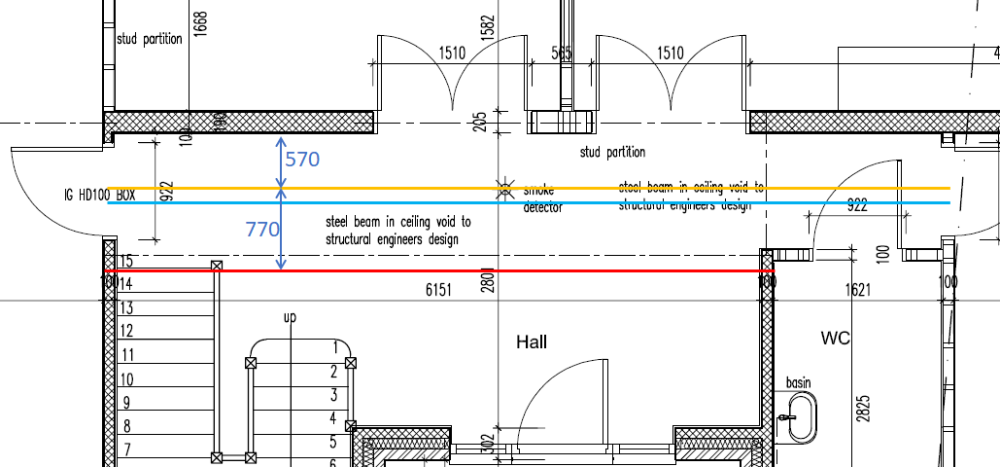
The downstairs hall has the landing above and will have 4 downlighters along under the landing. I've shown this below. The red line is the edge of the landing which is further over than previously expected due to the steel beam bearing on the right hand side. We're unsure which line is best for the downlighters: Orange: centred on the doors at each end Blue: centred on the ceiling section under the landing The wife and I are not in agreement as to which is the better choice and I'd like to see what others think 🙂 Arguments for each approach would be much appreciated. For reference, the lateral positions of the 4 downlights is centred on the stair turn, middle of each double door and then middle of WC door.
-
I sympathise with the brickies on this one. It's like changing the gate of your stride. It can be done but chances are it will mess up. I thought there was an upper limit as well but couldn't find it on a quick Google. There are enough variables with brick style, mortar and bond. We went Flemish, but I also like Monk Bond. English Bond can suit a certain style.
-
Wall plates on curved inner leaf wall
MortarThePoint replied to health mechanic's topic in Roofing, Tiling & Slating
Why do they want to make the new wall plate inline with the old? They haven't done a lap joint so it's not like they are tying them together. I agree with @PeterW, you can't put straps on that. I'm not sure I see the point in wider timber, but I can't see it would do any harm. Did the SE have any detail on this? How have they tied old and new masonry together? I'm not very experienced, so don't take it from me, but I thought it was usual to have an expansion joint at such a join? -
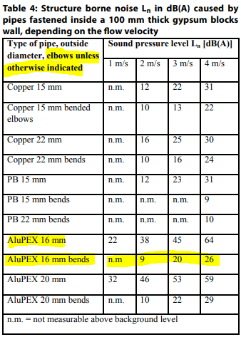
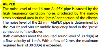
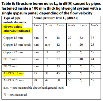
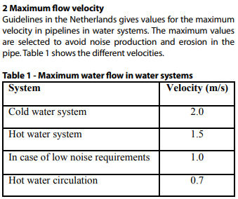
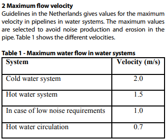
I think that is elbow dominated and using bends instead has a big reduction in sound levels. They were targeting 30dB(A) or less and the AluPEX 16mm bends were able to satisfy that at even 4m/s. AluPEX is the closest thing they have to Hep2O.
-
Some useful sound data in this paper. Looks like it is worth keeping the flow velocity under 1m/s. Pipe size 1.0m/s 1.5m/s 10mm 2.2 L/min 3.3 L/min 15mm 6.0 L/min 9.0 L/min 22mm 15 L/min 23 L/min 28mm 24L/min 36 L/min
-
This paper has some interesting data on pipe flow noise.
-
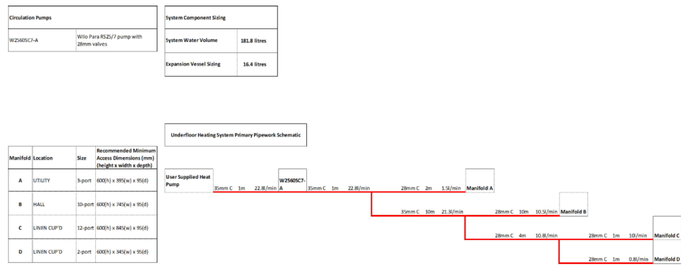
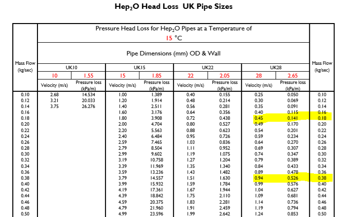
I was wondering whether Hep2O is good for the flow at return pipes to UFH manifolds? Originally I had a NuHeat design (feeds section below), but then swapped to WUNDA who didn't give a pipe spec for the manifold Flow an Return pipes. The design was also tweaked to be 3 manifolds. NuHeat said 35mm Copper for the higher flow pipes and 28mm Copper for the lower flow ones. The highest flow rate in the design is 22.8 L/min in 35mm Copper. That makes for a flow velocity of 0.46m/s in the 35mm Copper pipe (32.6mm ID). The largest Hep2O pipe is 28mm OD and the flow velocity would be 0.94m/s (22.7mm ID). NuHeat had a branched design though and I'm sure @Nickfromwales will advise 1-to-1 layout from the source (I'm learning). Then I'd only have a highest flow rate of 10.5L/min = 0.18 kg/s --> 0.45m/s pipe velocity. At what sort of flow velocity do I have to worry about a pipe getting noisy? The house we are currently in has noisy heating pipes, so I definitely want to avoid that. [Power check: f=22.8 L/min, dT=5C --> Q=0.38kg/s * 4.2kJ/kgK * 5K = 8kW. 11.2kW ASHP so may want a bit more flow or dT=7C] Wunda did give a flow for their manifold designs and the highest was 20.3ltrs which I presume is 20.3 L/min, so about double NuHeat and back to the around 0.9m/s pipe velocity. but I think that's over based on the power check, unless we only heat downstairs. ______
-
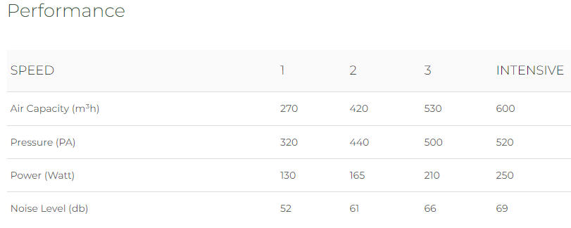
Are the hood manufacturers' numbers absurd, just designed to sell more expensive units, and the Building Regulations numbers more sensible? @Radian you may have some interesting thoughts after your recent beef burning. Power Use due to Extractor Fan: Building Regs sets out a requirement of 30 L/s if "cooker hood extracting to the outside" or 60 L/s if "no cooker hood or cooker hood does not extract to the outside". Cooker hood manufacturers on the other hand take account of the room size and base it on 10 air changes per hour [1][2]. Our kitchen is 6.4m x 4.7m x 2.6m, so about 80m3. That works out as 800m3/h or 220 L/s. In winter that is sucking out warm air to be replaced by outside air. The thermal heat flow is then: Q = flow(m3/s) * dT(K) * 1kJ/K.m3 = 0.22m3/s * 10K * 1kJ/K.m3 Q = 2.2kW (e.g. with dT=10K) If your cooker hood is part of you MVHR and it has an efficiency of nu_1 and your heat generation (e.g. ASHP) has an efficiency of nu_2 then the electrical power consumption is: P = (P_fan) + (Q * (1 - nu_1) / nu_2) In my case nu_1=0 (i.e. no MVHR which is a whole different discussion). If dT=10C (e.g. 20C in, 10C out) and the ASHP nu_2 is at 300% then that suggests a power consumption of: P = (240W) + (2.2kW * 1 / 3) = 1.0kW And 75% of the electricity consumption is related to the heat flow rather than the fan's direct electricity consumption. Based on cooking for 30 minutes per day, that works out as about 20p/day or £73/yr based on current (high, but perhaps to stay) prices. Running the Building Regs numbers (based on 30 L/s and scaling P_fan): P = (33W) + (0.3kW * 1 / 3) = 0.13kW ==> about £10/yr. A big difference. Hood Fan efficiency: The numbers in the table below are the maxima, not an actual operating point. But if it was an operating point, the efficiency of the fan itself would be: nu_fan = P_flow / P_electricity nu_fan = (Flow(m/s) * Pressure(Pa)) / P_electricity(W) = ((600/3600) * 520) / 250 = 35% That's not too bad but isn't an actual operating point so the efficiency is probably 20-25% in INTENSIVE mode. In mode 1, unadjusted nu_fan = 18%, mode 2, unadjusted nu_fan = 31%, and mode 3, unadjusted nu_fan = 35%. You're probably looking at an efficiency of around 20% best case. Remember, fans are really inefficient. but in extraction it doesn't really matter so much. https://www.faberhoods.co.uk/hoods/victory-2-0-integrated-cooker-hood/
-
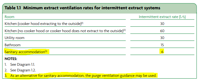
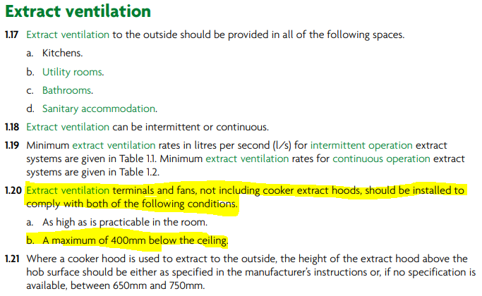
But looks like the window could count as an alternative so extractor fans not actually required for toilets (without bath or shower). I'm a but surprised so would need double checking with BCO. If extractor not required you could add one in a non compliant position.
-
Part F of Building Regs: https://assets.publishing.service.gov.uk/government/uploads/system/uploads/attachment_data/file/1045918/ADF1.pdf
-
Cooker Hood Ducting (Kitchen Extractor Fan)
MortarThePoint replied to MortarThePoint's topic in Ventilation
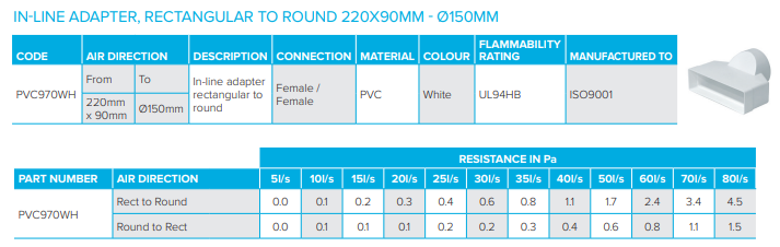
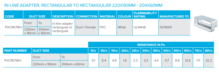
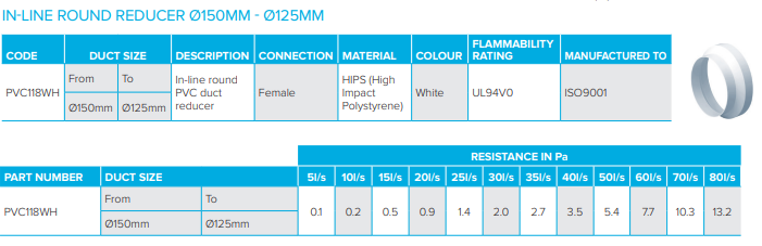
____________ ____________ ____________ From these, I'd guess 150mm Round to 204x60 Rectangular using a 150mm Round Bend and then Adapter would be about 30Pa @80l/s so much improved over the Plenum (~90Pa @ 80l/s) if space allows.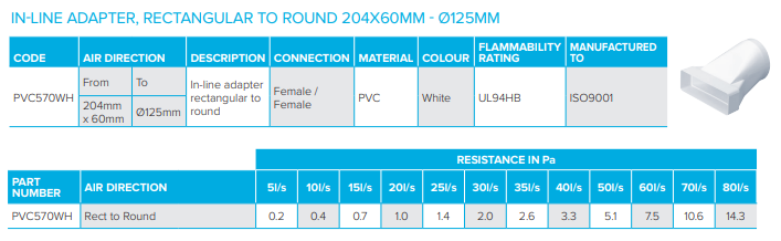
-
Cooker Hood Ducting (Kitchen Extractor Fan)
MortarThePoint replied to MortarThePoint's topic in Ventilation
Using the values in that Nuaire PDF, the total resistance becomes: 150mm Round Straight 600mm 1.1 150mm Round Bend 16.6 150mm Round Straight 200mm 0.4 150mm Round Tee 14.5 150mm Round to 204x60 Rectangular Spigot 90est. <<<< 204x60 Rectangular Straight 1450mm 11.3 204x60 Rectangular to 125mm Round Adaptor 14.3 125mm Round Straight 450mm 1.8 125mm Round Bend 26.4 125mm Round Straight 350mm 1.4 125mm Round Vent/Grating ?? TOTAL: 177Pa @ 80l/s (288m3/h) Half of that is from the plenum (aka "150mm Round to 204x60 Rectangular Spigot") which you'd almost always have in a system using rectangular ducting.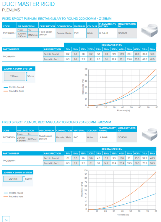
-
Cooker Hood Ducting (Kitchen Extractor Fan)
MortarThePoint replied to MortarThePoint's topic in Ventilation
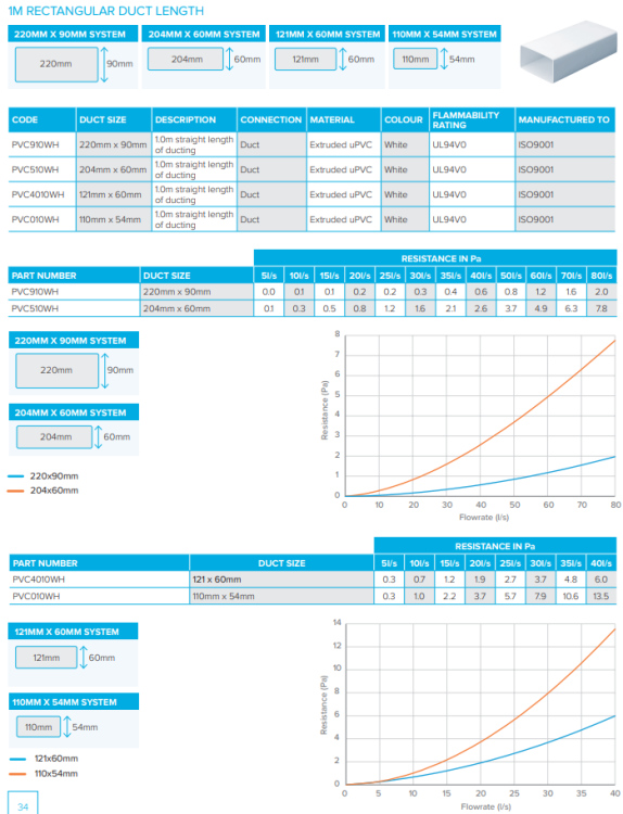
Here's a comparison of ducting resistance per metre for different types. At 288m3/hr it works out as: 144m3/hr 288m3/hr 150mm Round 0.4Pa 1.9Pa 125mm Round 1.4Pa 3.9Pa 100mm Round 4.1Pa 14.3Pa 220x90 Rect 0.4Pa 2.0Pa 204x60 Rect 2.1Pa 7.8Pa 121x60 Rect 6.0Pa - 110x54 Rect 13.5Pa - http://www.nuaire.info/catalogue/Nuaire_Ducting_Specification_Guide.pdf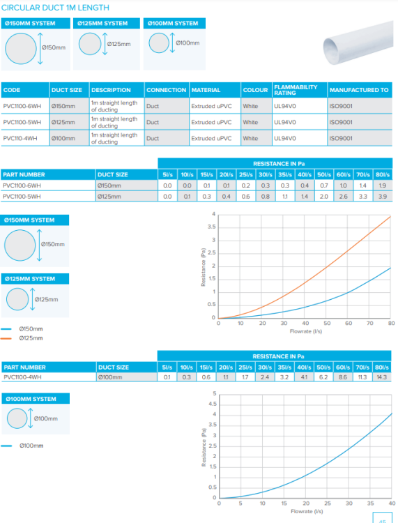
-
Cooker Hood Ducting (Kitchen Extractor Fan)
MortarThePoint replied to MortarThePoint's topic in Ventilation
Here's what it would look like using Rectangular ducting on its side: Passing from one of the extractors: 150mm Round Straight 600mm 150mm Round Bend 150mm Round Straight 200mm 150mm Round Tee 150mm Round to 204x60 Rectangular Spigot 204x60 Rectangular Straight 1450mm 204x60 Rectangular to 125mm Round Adaptor 125mm Round Straight 450mm 125mm Round Bend 125mm Round Straight 350mm 125mm Round Vent/Grating I read bends count as 1.2m equivalent. This has 4 bends so overall is equivalent to 8m straight length of 204x60 I'd guess. I've read it should be kept under 5m equivalent, but is there a building reg that needs satisfying?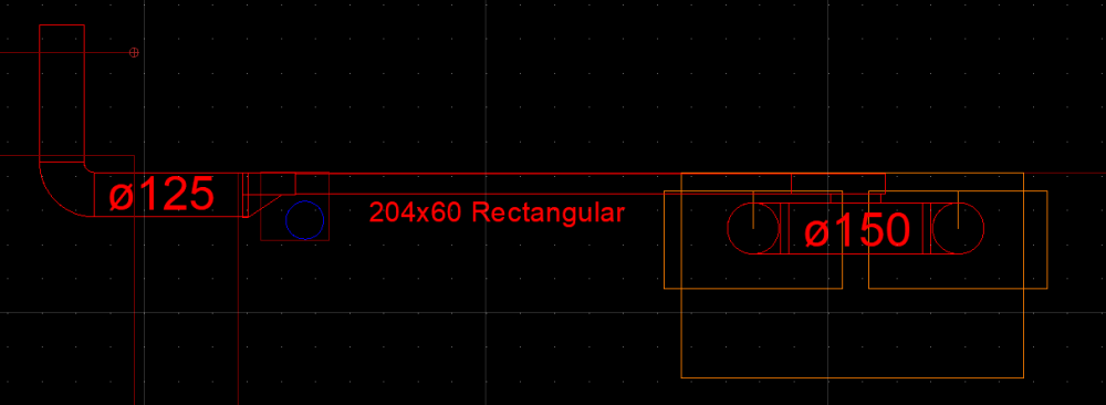
-
Cooker Hood Ducting (Kitchen Extractor Fan)
MortarThePoint replied to MortarThePoint's topic in Ventilation
Thanks @Nickfromwales, I've seen those parts from other suppliers and I can't see an Inline Rectangule to Round Tee. I was think along the lines of a straight section of rectangular duct with a spigot in the bottom for a 150mm Round to join. I guess I join the two extractors in 150mm Round and then adapt to Rectangular instead. Any reason Rectangular can't be used on its side, so the 220 or 204 dimension is vertical? -
Cooker Hood Ducting (Kitchen Extractor Fan)
MortarThePoint replied to MortarThePoint's topic in Tools & Equipment
This Thread has been stopped and restarted in the Ventilation section: -
Cooker Hood Ducting (Kitchen Extractor Fan)
MortarThePoint replied to MortarThePoint's topic in Ventilation
@Nickfromwales Posted: Any of this get you out of the 💩? https://www.tlc-direct.co.uk/Main_Index/Ventilation_Index/Ducting_Flat_6/index.html -
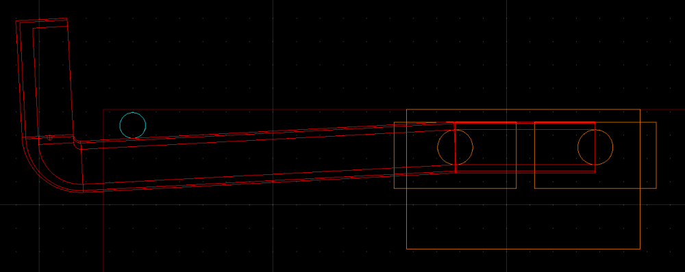
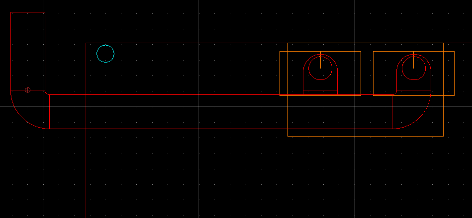
Our kitchen design has two side by side cooker hoods. Is there such a thing as an Inline Rectangular to Round 90 degree bend to put in the left hand hood as in the first image below or do I have to have them both bend/tee onto a straight run as in the second image. The blue circle is a soil pipe I have to get round and the dark brown lines are the wall surfaces of the kitchen. [NOTE: I accidentally started this thread in the wrong section so am stopping it there restarting it here]
-
Our kitchen design has two side by side cooker hoods. Is there such a thing as an Inline Rectangular to Round 90 degree bend to put in the left hand hood as in the first image below or do I have to have them both bend/tee onto a straight run as in the second image. The blue circle is a soil pipe I have to get round and the dark brown lines are the wall surfaces of the kitchen.
-
By that I assume you mean turning down the flow on loo cisterns etc so showers don't get starved. I like the idea of being able to isolate the family bathroom. A conventional plumbing setup wouldn't have remote balancing. I could use a pair of lever isolation valves for the family bathroom.
-
Yes, I expect 10mm would be fine for basin cold as well as hot. Also, should be OK to loo cisterns. I think a big flush these days is something like 6L and 10mm pipe can pass that over 10m at 1.5bar in 1 minute. How do you feel about what I should do in terms of wall and floor finish. What's the norm there? Bare blockwork feels a bit unfinished
-
A 25mm SDS bit would leave only 15mm of block between the holes. That's removing 63% of the material. Surely it's not a good idea to weaken a wall to that extent across 1.2m of width.
-
I presume you mean drill from the lower left which is the utility. It would be no drama for a few, but having a line of holes at 40mm centres isn't so appealing. I suppose I could stagger them vertically as well to make the hole c/c about 60mm. It's still across about 1.2m of wall if going fully 1:1 radial. Watched some videos of people core drilling at 45 degrees but that's with a pretty beefy jig.
-
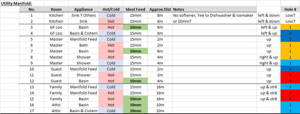
Ignoring the Kitchen feeds, which may be able to be down low and so much more choice there, the 38mm core holes could be split as follows: That's a total of 4 core holes vs the 1:1 needing 10 (exc. kitchen). The compromises are: Master Cold manifold feeding bath, basin and loo cistern. May make sense to just use accessible Tees. Items not individually isolatable. Guest Cold manifold feeding shower, basin and loo cistern. May make sense to just use accessible Tees. Items not individually isolatable. Family Cold manifold feeding shower, bath, basin, and loo cistern. Would be kept accessible but items not individually isolatable. Family Hot manifold feeding shower and bath. That's effectively a Tee. Would be kept accessible but items not individually isolatable. One of the holes has 3no. 15mm Hep2O pipes in. That is a squeeze and may require some different conduit (3no. 15mm circles fit in one 32.5mm circle and the solvent weld pipe I am using as conduit is 32mm ID). Attic is a future renovation opportunity to add a loo. There are two compromises here (a) it is 10mm hot and cold (b) it's hot is shared with three colds so not ideal but feels minor. Those feel like minor compromises for the significant benefits of reduced core holes and pipe grief. The coarsest level of isolation is at the room level (Family H & C, Master C, Guest C). In terms of in use, I think the only compromise is: It does have the Guest loo cistern feed from the same main 15mm pipe as the Guest shower (cold). Probably worth stepping the loo cistern down to 10mm to hopefully keep the shower as the preferred path, though I could adjust the cistern inflow if required. Basin is also fed off this, though that is less binary than the loo filling. I don't expect the bath and shower in the same room to be run at the same time.
-
The S-bends can be eased but using the dimension in and out of the diagram to help a little.


