


MortarThePoint
-
Posts
2198 -
Joined
-
Last visited
Everything posted by MortarThePoint
-
Door Linings: Fixing placement
MortarThePoint replied to MortarThePoint's topic in Doors & Door Frames
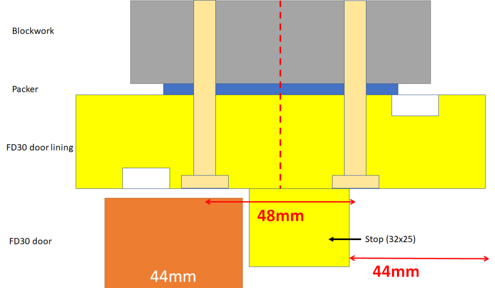
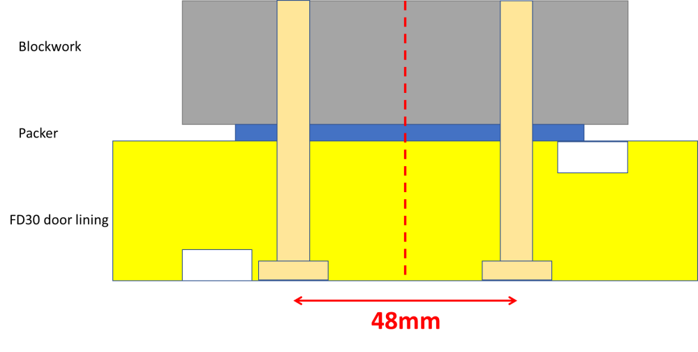
The stops for the door lining are huge (32mm x 25mm) so are going to look a little strange compared to what I am used to. I've updated the diagram for the full (un trimmed) 132mm door lining as well as adding the door and stop. The outside of the door is quite far recessed relative to the lining which would additionally have architrave on. I have four doors in a row along a corridor and all the door linings should be lined up. I was planning to trim down (10mm) one of the door lining's depth to make the plaster thickness more sensible (only have to do it on one). That would have the effect of pulling the door outwards compared to the other doors by the amount trimmed off the lining (10mm). That could look bad so leaves me with a couple of options: Don't trim down the door lining and have some fat plaster. Set the doors of the other rooms slightly further outward to lessen the impact. That could look bad as it would make the surfaces of the door and the lining not line up on the inside and look funny Normal: If door pulled outwards: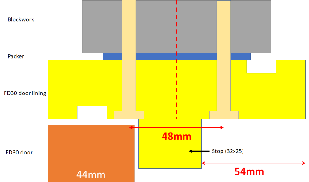
-
Plastering over the end of hollowcore
MortarThePoint replied to MortarThePoint's topic in Plastering & Rendering
Ah, the hollow core holes I asked about are internal but in a wall to be wet plastered. So should that be stainless mesh if outside being rendered and galvanised mesh inside if being wet plastered? Or still go with stainless mesh if covering hollow core holes, but galvanised mesh OK internally elsewhere? -
Plastering over the end of hollowcore
MortarThePoint replied to MortarThePoint's topic in Plastering & Rendering
Is that because of the hollow core holes or would you use stainless mesh when meshing other interior walls -
Plastering over the end of hollowcore
MortarThePoint replied to MortarThePoint's topic in Plastering & Rendering
Is it Stainless mesh because it's not sealed on the other side? -
Door Linings: Fixing placement
MortarThePoint replied to MortarThePoint's topic in Doors & Door Frames
Could have done with those on the engineering bricks. -
Door Linings: Fixing placement
MortarThePoint replied to MortarThePoint's topic in Doors & Door Frames
Another silly question. I don't need to adjust their height do I. Just checking they don't come with extra. The legs are 2010mm. That feels about right for 1981 doors assuming. 2010-1981=29mm. Allowing 4mm at the top allows 25mm at the bottom. That needs to accommodate underlay and carpet as well as a small gap. -
Door Linings: Fixing placement
MortarThePoint replied to MortarThePoint's topic in Doors & Door Frames
@joe90 you mentioned in another thread you used screws hidden by the stop. We're there any issues not having pairs of screws? How many did you use on each leg? Did you go with wood screws and plugs? -
There is quite a handy guide for installing door linings: https://www.juliancassell.com/2564/fitting-a-door-lining One question left open though is screw placement for 5 pairs of screws in each leg. Vertically, evenly spaced makes some sense with one 50mm - 75mm from each end. Is there the risk of clashing with hinge placement, or that's always cut on site so you can tune for wherever the lining fixings are? 75mm at each end would make a lining for 1981mm door (2010mm leg) at 75, 540, 1005, 1470, and 1935. Horizontally, it gets more complicated. I have FD30 linings with a groove for the intumescent strip (starts 15mm in from edge and is 15mm wide). They're in blockwork walls. I'm probably trimming down from a depth of 132mm to 124m using a jointer as my plasterer wants them smaller, but that needs to be on the non-strip side. The timber stop that gets added later (not shown below would likely overlap the screw heads slightly, but that should be OK. I am thinking of using 7.5x102mm Frame screws (link) or 5.0x100mm screws (links) and plugs (brown or red).
-
Temporary Stairs - Cut and Join two Halfs
MortarThePoint replied to NewToAllOfThis's topic in General Construction Issues
Thinking about it again, that wouldn't be right. The Joist dimensions would be the same as the stringer dimensions, but the load would be reduced by COS[angle]. So if 47x250 the span can happily be 4.47m span @600mm spacing and live load of 1.5kN/m2 / COS[30] = 1.73kN/m2. Point loading mid span two joists -> 1.73kN/m2 * (2*0.6*4.47) / 2 = 4.6kN load capacity. Very similar. 38x145 the span can happily be 2.85m span @400mm spacing and live load of 1.5kN/m2 / COS[57] = 2.75kN/m2. Scale for width 2.75kN/m2 * (27/38) = 1.96kN/m2. Point loading mid span two joists -> 1.96kN/m2 * (2*0.4*2.85) / 2 = 2.2kN load capacity. Very similar.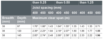
-
Temporary Stairs - Cut and Join two Halfs
MortarThePoint replied to NewToAllOfThis's topic in General Construction Issues
I was wondering, did the screw shear or the wood split? -
Temporary Stairs - Cut and Join two Halfs
MortarThePoint replied to NewToAllOfThis's topic in General Construction Issues
Sounds hairy, hopefully at the bottom -
Plastering over the end of hollowcore
MortarThePoint replied to MortarThePoint's topic in Plastering & Rendering
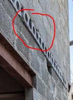
I'm avoiding spray foam so not that. It does overhang slightly in one area. I need to wet plaster so more tricky. @nod any tips? -
@Conor I pinched part of one of you pictures above. How did your plasterer deal with the ends of the hollowcore? I have this in some places too.
-
Temporary Stairs - Cut and Join two Halfs
MortarThePoint replied to NewToAllOfThis's topic in General Construction Issues
Nice! I think that's the proper way to do it but takes more time and I expect the routing weakens the stringer slightly. You can get brackets that go under stair treads but they are crazy expensive. I wondered about a bit of batten screwed and glued to the stringer (see below). The nice thing about the video approach is that the blocks transfer the load down to the next tread and so on. Doubles the stringer wood though.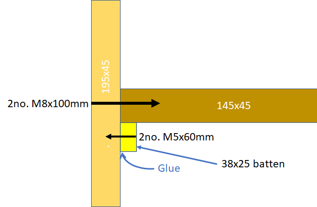
-
Temporary Stairs - Cut and Join two Halfs
MortarThePoint replied to NewToAllOfThis's topic in General Construction Issues
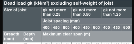
The stair in the video is a pretty low angle (30-35deg?) so that makes its life harder. There are space saving stairs online (57deg) with just 142x27 stringers but that seems too flimsy to me. My intuition is telling me that the moment and stress ends up along the lines of considering a joist with length equivalent to the horizontal projection (L_joist=L_stringer/COS[angle]=h_stair/TAN[angle]) of the stair and joist height equivalent to the vertical depth of the stringer (so h_joist=h_stringer/COS[angle]). Is that correct? If that is correct, the equivalent joist to the video would be about L_joist=2.4m/TAN[30] = 4.1m, h_joist=225mm/COS[30]=289mm. NHBC tables don't go up to 289mm, but extrapolating each 25mm step adds 0.45m of span (gk=0.25, spacing=600mm) so that would suggest (for C16) 47x295 joists would be good for a 5.37m span @600mm spacing and live load of 1.5kN/m2. That's a UDL, so a centre loaded equivalent would be half the UDL loading so 5.37m * 0.6m * 1.5kN/m2 / 2 = 2.4kN per joist. I know the treads are wider than 600mm, but this attempts to understand the point (tread) loading. As there are two stringers, it would double that to 4.8kN load capacity. Unlike a joist the loading is much more aggressive due to the bouncing motion of people climbing the stair. Think of a 100kg builder with a 25kg bag of plaster under each arm playing trampoline in the middle of our stair. For the space saver, the tables don't go that thin, but can scale: 142mm/COS[57]=260mm. 27x260 should be good for 1.5kN/m2*(27/38)=1kN/m2 and a span of about 4m(!) where as the stairs projection is probably more like 2.4/TAN[57]=1.6m. Does that make the equivalent joist point load capacity around (4m / 1.6m) * 1kN/m2 * (1.6m * 0.6m) / 2 = 1.2kN. As there are two stringers, it would double that to 2.4kN load capacity. All nonsense or vaguely right? 🤠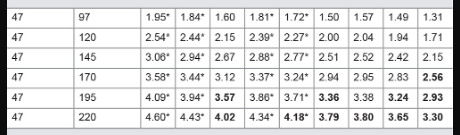


-
Temporary Stairs - Cut and Join two Halfs
MortarThePoint replied to NewToAllOfThis's topic in General Construction Issues
Look awesome! Did you use Coach Screws or woodscrews (6mm)?) to attach the treads to the stringers? How have you attached it at the top? I've bought some 8x2 for my stringers and 6x2 for treads. I'd like to go with Galvanised treads as that was my plan for the garage but I am re thinking that because: They have doubled in price so would cost £400+fixings for the garage stair As they are open any dirt will fall straight through to whatever is underneath. I could address using something underneath (Perspex?) but more cost They bolt to the stringer quite easily though.
-
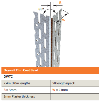
Walls are blockwork and are to be wet plastered. Plasterer specifically asked for Catnic beads, though said the BG ones are good too. I'm sure it's a matter of whatever you are used to, but I wanted to get as asked. I've ordered these, but they have a 23mm bit. Do you know who does a 40mm one? I'm guessing he wants the scrim tape for the plasterboard ceilings and partitions
-
Mostly hairline in mortar lines
-
I have to tidy up a bit too as there are piles of various materials everywhere.
-
I'm preparing for the Plasterer who is coming next week which is exciting. He's going to be plasterboarding the reveals and doing all the beads and scrim tape. Is it best to use moisture resistant plasterboard in window reveals? Is there anything I should do with blockwork cracks? Mesh? I've got them under the longer windows. I'm now frantically creating piles of sawdust as I prepare the window boards and door linings.
-
I was thinking to do that I've also found these hole reducers which are a good use of a laser cutter. https://www.ebay.co.uk/itm/123992774715 You can get fire rated too but not so DIY https://www.downlights.co.uk/integral-hole-converter-plate-for-70-100mm-hole-sizes-evo-fire.html?gclid=EAIaIQobChMI7eDLzOKy_QIVE49oCR1DlQ7REAQYDyABEgIh9PD_BwE#hole-converter-plate-for-70-100mm-hole-sizes-integral
-
Yes, so I'm thinking quite diffuse / wide angle is best. Those ones claim 110 degrees
-
Good point! Benefits to staying standard.
-
So many ways to get it wrong I like these (link) which give off a nice diffuse light. They are very slim, but require a large (105mm) hole. Lumens per watt figure isn't great though. https://auroralighting.com/Products/Download/EN-PL06B?Code=EN-PL06B&IsMicrolights=False&Brand=Enlite
-
I think the wife wins it then, fat lot of good you lot were 🤣 Just kidding, all good thoughts and you've won me round. Looking at it from the main entrance you're not going to perceive the difference and walking along the hall from one end to the other the blue line would grate. Closer to the wall may be an option, but I think the panelling and general aesthetic will mean the Orange line wins the day. Where's my humble pie cook book, in some dusty corner somewhere.


